Leaderboard
Popular Content
Showing content with the highest reputation on 07/01/2017 in all areas
-
3 points
-
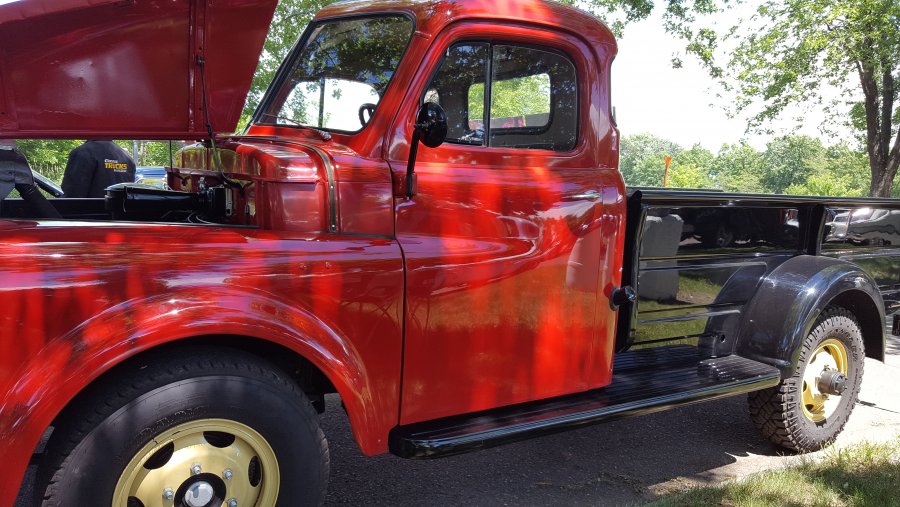
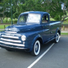
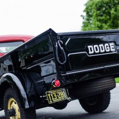
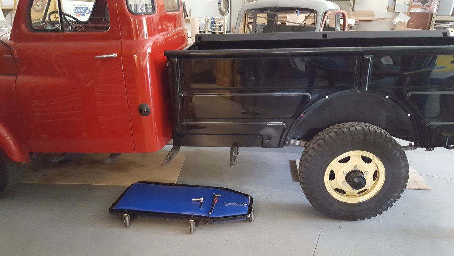
So Ed came over the other night to help pull the fender off FEF to get it stripped and repainted. I was worried that the body caulk I used as a gasket would be tough on removal. Turns out after bolt removal as Ed moved in the bed the fender fell off right on to the tire! FEF is going to be in the Concours d'Elegance at the end of July and is getting some stuff fixed up.3 points
-
2 points
-
I'm totally sure they were painted by humans with a spray gun in hand at the mopar factory build lines in 1951 My high school shop class took a road trip of several hours to tour the Ford factory in the S.F. Ca. bay area in 1968. We had a tour of a Mustang build line where in the body paint area the painter had a row on spray guns on each side of the line in the spray area. As each car approached he looked at a list of builds and what color to spray. He would grab the right color spray gun needed and cleared it out, adjusted as needed then jumped to the other side and did the same with the same color gun there and then started spraying most of the top panels and side of that car then jumped to the other side and finished the job. Boy that guy was fast and tired at the end of his shift! Paint looked great after coming out of the oven! DJ2 points
-
JB, I don't understand how an engine rev limiter that governs the throttle can prevent over-spin when coasting downhill using the engine compression as an additional brake. Seems to me the rev limiter would not work in this application???2 points
-
2 points
-
Thanks for the compliments. It is guys like you and the others on this forum that provide the inspirations to innovate!2 points
-
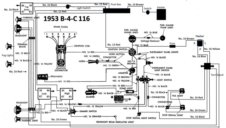
So I have decided to switch my 53 B4C over to 12 volts. Here is a wiring diagram I plan to follow when redoing the harness. This assumes a one wire alternator, changing the heater motor to a 12 volt motor, change the horn to 12 volts, and add relays for the fog lights and one each for the high and low beams. Also switching the wiring on the Ammeter and the coil (a 12 volt coil with PerTronix ignition. Also a blade style fuse box. Anyone see anything I missed? Thanks in advance for your help and if this looks good maybe it could help others make the switch to 12 volts.1 point
-
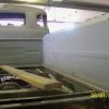
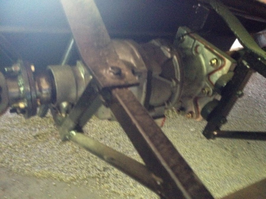
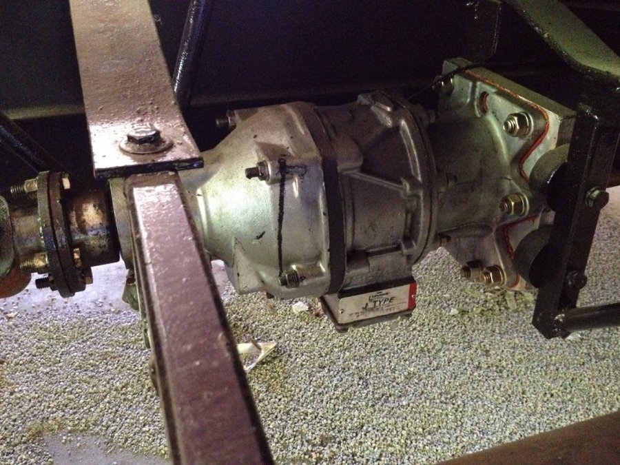
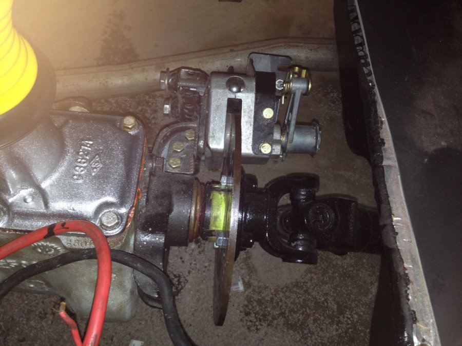
A lot of us want to keep our trucks as original as possible and, at the same time, improve the safety and performance to drive comfortably on today's roads. Along with brake upgrades, wringing more horses out of our flatheads, adding seatbelts and tightening up our suspension components, many of us have asked--how can I cruise at 65 while keeping the RPMs in a decent range? The three "big" solutions that stand out are a- swap transmissions for something with an overdrive, like a T-5 or an A833, b- swap rear ends, or c- add an overdrive, such as a Laycock. The problem with a- is that the engine may need to be pulled, an adapter plate might be required, a new hole in the floor must be cut and then there is the clutch... and what about the parking brake? The second option, b- presents the problem of gearing that is too tall for the torque output of the engine, especially if the flathead is wimpy, such as a 201. So... c- was the option that I was most interested in. No modifications needed for the parking brake, transmission or engine. Gear Vendors sells a unit, or you can opt for the route I followed: find a Laycock J-type from a donor Volvo. Here are the modifications that I did: The old truck came with the factory optional, slightly more desirable 4.10 ratio rear end (as opposed to the 5.63 stock rear end), so it could putter happily at 45 MPH and, sounding like a manic sewing machine, hit 65 MPH. I wondered about switching out the rear end—and had picked up one that was a 2.80:1 ratio. After doing a few calculations, I realized that the rear end would make the underpowered engine even more so. Maybe an overdrive would be better? I began a search that led to a Laycock model J overdrive, about the size and shape of a small watermelon. It fit nicely in mid-frame. I installed two drive shafts, one from the to transmission to the overdrive, the second from the overdrive to the rear end. It is important to mount these with the correct angles to preserve the u-joints. I also had to move the gas tank over by about an inch to fit around the overdrive. That wasn’t such an issue—the tank needed to be replaced, anyway. The Laycock overdrive is common on older Volvos. These are often listed on ebay—without the front drive shaft. I found a complete one, cut off the end of the shaft, and had a local machinist weld a u-joint receiver onto the end to accept a short drive shaft connection to the transmission. I fitted an aluminum plate with an oil seal for the front end of the overdrive unit. Ran a 12 volt wire to a fuse and button mounted below the dash--and added a pilot light that shows when the overdrive is engaged--and that was it. Simple! (an aside: make sure that the overdrive isn't engaged when putting the truck in reverse) My biggest issue was with the speedometer output shaft. The truck cable housing wasn’t long enough to reach and the knurled connector didn’t fit. I am working on an alternative, though. A sensor connected to an Arduino, to read the speed and drive a little electric motor connected to the speedometer head… I’ll probably use a GPS to provide the speed signal. BTW, in the process of putting the overdrive in, I discovered that the parking brake drum had developed a number of fractures and was close to exploding into fragments, so I replaced the whole arrangement with a snowmobile mechanical disc brake. That set up works very well for my purposes. Another tip: I put Lucas transmission oil additive—the stuff that you see on the car parts counters—into the non-synchro transmission and it worked so well that, for most of the gears, I can shift as if the transmission is synchro. Very nice. So, does the new setup work? Oh, yeah--I say with a big smile on my face. Oh, yeah, it is very, very cool. My 201 has no problem running the overdrive, and as a side benefit, I get an extra gear in 2nd and 3rd that makes puttering around town a lot more fun. Plus, the overdrive makes it easy to downshift without double clutching. I can wave to people as go around corners! Here are the pictures:1 point
-
You should check out Alabam's approach. We just let our's resign in a plea deal to escape a jail term. Unfortunately, it wasn't before he was able to appoint his Attorney General to a U.S. Senate seat in an attempt to hinder the investigation. Hope to remedy that in an upcoming special election. One of our previous governors just finished his jail term for corruption. Oh, me . . .1 point
-
No need to withdraw, I already read your comment and truly appreciate your opinion and that of all other subject matter experts on this site. Like I stated before I am no expert and just learning. I'm sure everyone learned one way or another. I joined this site and plenty others to learn and possible one day provide feedback and knowledge to others. Along the way I have also learned to appreciate the craftsmanship of this and other skilled trades. I'm pretty much more of a custom body and paint guy. I am on other more paint specific sites and love to share my advise to other. If they chose to follow the advise or not its ultimately up to them. I personally love sharing that knowledge to other eager do-it-yourselves because one thing we must all ultimately agree on is that one day we will not be on this planet. In my opinion, it will be nice to know that the DIY hobby, whether its car related or not, will still live on through generations.1 point
-
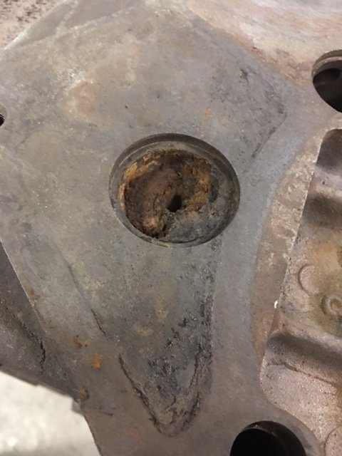
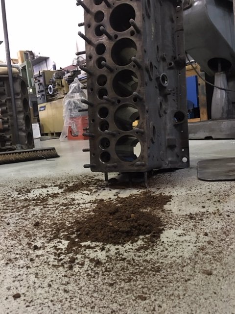
@40desoto is the engine still in your car? I would refrain from re-installing the head, before testing for valve sealing. The playdough dam mentioned works but is not necessary. I found that a large syringe, filled with kerosene worked well. Make sure valves are completely closed tight with springs installed. Back off the tappet adjustments. With valves fully closed, wiggle tappet up and down to to ensure its not in contact with valve stem. Drinble a good amount of kerosene around the valve edge where it meets the block. Keep some paper towel in place to stop any kerosene from flowing into the adjacent valve that shares the same port. It does not take long to see the results. Within a few moments you'll see kerosene flow down into the port if the valve is leaky. Having the inner fender window removed, and wheel off so you can look into the port, is a big help here. My understanding is once the head is torqued down, the metal gasket has done it's job, once. Removing the head again to lap valves again, in my opinion means a new head gasket. This why I prefer to ensure valve sealability before I re-install the head.1 point
-
Looks like it would would be a good time to turn it into a at rod!! The missing fender looks awesome1 point
-
9 out of 12 valves are sealed tight. 3 others I need to remove and spend some more time lapping. First time doing this task, I'm ok with that. I'm getting there.1 point
-
Your application of this overdrive, may well have driven down the price of a MOPAR OD. Does my sketch roughly represent what you did?1 point
-
You deserve them. What you have done is shown us all "another way" to get the most from one of these trucks without messing about with it too much. Very...very clever too. To me at least these sorts of mods are totally sensible if you wish to really use your truck without completely altering it's true character. Kudos. Jeff1 point
-
I got the overdrive about four years ago via eBay. At that time, it was a couple hundred dollars. The trick is to find one with the front shaft still attached. There are a lot of these around, so you should be able to find one at a wrecking yard. Google Laycock J-type overdrive to get an idea of what they were put into and how they work. To mount the OD, I removed the truck bed, then ran a support from the mid cross member to the back cross member, next to the gas tank on the left side. The tank had to be moved over by an inch to the left. Mounting: Use rubber bushings at each of the mounting points. Tail: The OD tail mount is on the bottom. Brackets were hung to accommodate the tail. See the pictures for an idea of how it was done. Front: I drilled and tapped the front aluminum plate for 3/8" bolts, then dropped brackets alongside the front to line up with the OD. The aluminum plate was what I used to cover the front of the OD. It was drilled to accomodate an oil seal for the shaft. One suggestion is to refresh the OD with new O-rings before installing it. It is a simple job, and is important for creating the hydraulic pressure that is needed to shift from high to low. It is also a good idea to drill a vent/fill hole near the top of the OD adapter case.1 point
-
I just got my 3 window coupe home last night seems I need to do the exact same thing you did over past 2 years what was the cost of the wiring harness that's my first step rewire before I create a fire my car has not ran since 1992 when it was parked in barn mice an dry rot has took its toll on the wire coating did the wiring harness fit as if it was factory made ? I got lucky got 5 rims and 4 hub caps along with a set of the phony fake white walls1 point
-
The P15-D24 Forum was represented at the digging up of the Belvedere. First car belonged to Pete aka "Blue Skies" from Montana (as I recall. anyone feel free to correct me) The engine was very highly modified and looked great. These cars were all driven to the event. Then, we had John Smeltzer (on R) (Me on left) from Colorado with his 1949 Plymouth My 47 P15......from Missouri Then there was Mr Don Coatney from Murfreesboro, Tenn (now of Indiana) in his blue P15 with a DeSoto flathead engine. There was a little "street race" between Blue Skies and Don since both had been extolling the virtues of his respective engine build. A fun event for sure.1 point
-
1 point
-
1 point
-
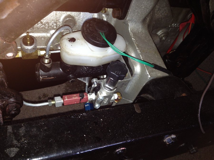
The old single cylinder MC featured a three-eared mounting bracket that bolted directly to the bell housing. After a lot of research, I found a newer dual MC that bolts on with little modification. It was used in Toyota Celicas from the 1980’s. It cost $40 and has standard 3/16 flare SAE threads and an 15/16ths bore. The one I purchased was listed as a New Qualitee 6679750 Brake Master Cylinder 86 - 89 Celica incl. GTS w/o ABS. Last summer I worked on a 1994 Toyota Camry. From what I could see, the master cylinder is the same configuration as the Celica, so that might be another alternative. Each of the mounting holes had to be elongated by about 1/8” to fit the existing pattern on the bell housing. I used a rat tail file to make the adjustment and it fit in perfectly. The push rod had to be shortened by about an inch and a half. The 86-89 Celica master cylinder bore is 1”, while my old Dodge MC is 1 1/4” in diameter. The slightly smaller diameter provides more leverage, and the result is a pedal that feels and functions like a power brake. I mounted a proportioning valve and the residual valves. The MC is not much higher than the discs, so the residual valves help prevent back-filling of the MC. To prevent uncontrolled skids, a metering hold-off valve was added. Its purpose is to engage the rear brakes first.1 point
-
1 point
-
I don't know if anyone is following this thread anymore--want to give a brief update on the Toyota m/c and how my brake project turned out: I installed disc brakes on the front and back of the truck (thanks, Rusty Hope!), and used the Toyota master cylinder along with the appropriate pressure and metering valves. The m/c fit like it was made for the truck. No need for power brakes, this setup has plenty of power for stopping, with little effort on my part. So if you are looking for an m/c upgrade, I would strongly recommend the toyota version. The overdrive was well worth the effort, too. The cab is much quieter, my rpms are much lower, and I get the added benefit of easy upshifting/downshifting with the press of a button.1 point
-
He should carry a card with his address on it in his pocket so he'll know where he lives.1 point
-
1 point
-
Too wide of seat to valve face contact can be a bad thing. Carbon flaking build up on the seat can occur because of this. The correct .060" to .085" seat to valve face contact width will help to prevent valves from not completely seating at times because of this possible carbon contamination. The correct seat width will chisel any carbon flakes and prevent carbon build up on the seats causing over heating valves and loss of compression. Seat contact area is critical too... not all the way out to the valve face margin and not all the way in either.1 point
-
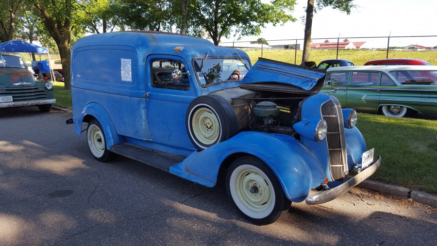
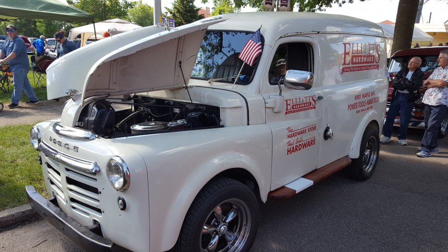
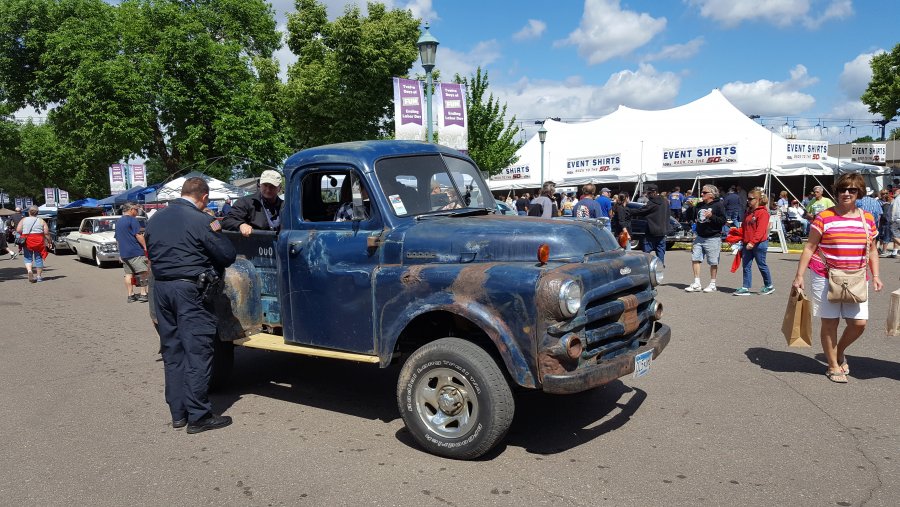
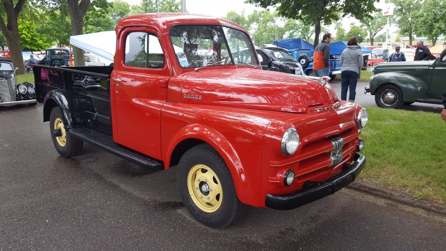
Sadly I could not attend Friday Back to the 50's, but spent a good deal of time there yesterday. My knee is having issues so not much walking around, but I ran into lots of friends and met a few casual posters here. I saw Mike's truck with his dually conversion and it looks sweet! Met a casual poster that has a nice old B1 or B2 with some interesting mods. In order the pics are of waiting in line, at the show, a humpy!, a panel, a B4 on a frame swap and FEF's first real rain shower (No leaks!).1 point
-
First off how is the wheel alignment?...then tyre pressure?....I'd be checking front end wear in no particular order....tie rod ends, kingpins, upper & lower inner & outer pins & bushes also does the 54 with P/S have a rubber steering box isolator between the box & chassis and outside the chassis........also how are the rear spring shackles and front bush/pin....finally what tyres?............crossplies or radials?..............when I got my supposedly "restored" 1941 Plymouth I had to replace the tie rod ends, kingpins, steering isolators inner & outer and rear spring shackles..........got it reasonably o/k but after a few months the crosssply tyres reminded me why I didn't like them when I 1st got my 1940 Dodge 45yrs ago......... so I replaced them with real tyres, radials and the wandering finally went.....my Oz 2 cents worth....... .........And 1939-1956 Mopars do NOT have any actual caster adjustment BUT " the proper caster angle of -1 to +1 degree, 0 preferred is obtained by the proper assembly of the upper and lower control arms. If the caster angle does not come within these limits look for bent parts in the front suspension system." ...... as quoted from the 1946-53 Plymouth Service Manual, the Motors Auto Repair Manual also advise that the caster is not adjustable but is correctly set when the camber eccentric bushing is set correctly............ ..andyd1 point
-
You can pull the horn apart and nothing will fly out. There is a metal vibrating plate mounted between the electrics/magnet backing plate and the horn 'trumpet'. You will be able to powder coat the 'trumpet', but I would be reluctant to heat up the rear backing plate which houses the coiled wire, electrical points, and magnet. You should find that you will need to make up new round paper gaskets which fit on either side of the vibrating plate as the old paper ones become brittle over the years - they are required in order for the horn to work. I am working on restoring another set of dual horns for my 53 truck at present, but they will be painted in 2-pak gloss black like the ones which are fitted to my 52 truck. I have attached photos of horn insides and outs for you...1 point
-
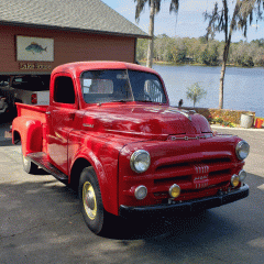
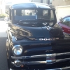
Been a while since I posted; just wanted to share some pics with everyone. Wife, kids, and I take the '51 out a few times a week for evening cruises. We're usually out for an hour or better. More on weekends. Sometimes I go 40mph, sometimes 55. Gets better mileage at 55: been averaging over 20mpg...no kidding! If we lug around at 40 it gets between 15-18. It always calms me to take the old Dodge for a ride. Its all original, and we enjoy it like that!1 point
-
Our development has a different name for each style of home. We bought a Meadowbrook. True story....my wife and I were trying to choose between the Meadowbrook and another model the builder was offering. We really couldn't decide. On the way to the sales office to sign the sales contract, a Dodge Meadowbrook passed us on the road (pretty unusual on a foggy morning in 1997). That event made the decision for us.1 point
-
ATF will not hurt it. ATF has been used for a long time to help free up sticky lifters.1 point
-
It's a mad, mad, mad, mad world again 1962 imperial crown convertible1 point
-
It's a mad, mad, mad, mad world! This 1963 classic movie was on free TV here yesterday. First time Ihad seen it (sheltered upbringing) and it is hilarious! It is essentiall a car chase/road movie featuring a massive amount of venhicles along the way. Jonathan Winters drives a furniture truck which looks classic but i do not know the make. Milton Berle drives a 1962 Imperial Crown convertable. But for you Chrysler Military Vehicle enthusiasts apparently the tow truck is a 1951 M37 owned by Ray & Irwins Garage. Enjoy.1 point
-
HOLLYWOOD was searching for something else on the 'net and found several pics from Rounders:1 point
-
1 point
-
HOLLYWOOD Was watching Used Cars for the nth time and finally noticed the beast in the background...the DVD commentary is almost as funny as the film1 point
-
HOLLYWOOD I'm in a rain delay at the house, so I was watching that Argo movie I picked up at Target on sale a few weeks ago...look what was at the airport at about 1:25...1 point
-
1 point
-
1 point
-
1 point
-
1 point



.jpg.4b5afc7ba3a8c980b1212cef1b9c7150.jpg)
.jpg.5a8da475075b4d7ec6a8322c9020cb67.jpg)




.jpg.206ed872d7a4764261f1c3a0a0c9a02b.jpg)
.jpg.42b6713e2fb7f0a8327b3fb8422ab898.jpg)
.jpg.8a8e80b2c98ec12a9fd361a3582093da.jpg)


