
LazyK
-
Posts
381 -
Joined
-
Last visited
-
Days Won
1
Content Type
Links Directory
Profiles
Articles
Forums
Downloads
Store
Gallery
Blogs
Events
Everything posted by LazyK
-
bigger gap = less dwell smaller gap = more dwell
-
i agree. mounts to the two bottom bolts that hold the side cover on. second is also part of the parking brake assembly. one end hooks in the a cross member just rear of the transmission and the other end attaches to a spring that is then hooked to the parking brake cable. the spring helps release the parking brake
-
FINALLY - My 1948 B-1-D Build Thread, 33 Years Later
LazyK replied to billrigsby's topic in Mopar Flathead Truck Forum

-
diagram does not show any horn wires connected to the ignition switch my wiring diagram shows we are working with 3 green wires. and 1 red wire. unless someone has rewired the car and used different colors I've sent you a personal message
-
I think we have a communication, teminology problem here. here is what I see Toms first(top) photo shows a factory relay(tom calls it a horn switch) second photo(botom) shows i believe Toms car with the factory relay and to its left an after market relay The factory relay needs 4 wires to operate The after market relay only has 3 wire. What appears as a power wire direct off the voltage regulator to the center terminal(B) and an added wire(since it is not wrapped in the original harness)to the left(S) terminal, I can not see what is hooked to the right(H) terminal. for an unknown reason a previous owner added the aftermarket relay. As wired the horm works any time you hit the horn ring on the steering wheel. When wired as factory the horn only works when the key is on Again I say get a factory wiring diagram and a VOM(voltage ohm meter) and test/trace out the wiring. there is a possibility the factory relay was bad and the previous could not find a factory replacement. its operation can be confirmed using the VOM if Im wrong someone will correct me, that is the good thing of this site
-
So, no more side trips to Algeria for Gasoline....
LazyK replied to Eneto-55's topic in Off Topic (OT)
I see the label says race fuel but i cant imagine enough race cars in WI to justify this at the pump. is it also marine(boat) use? -
I'm just going by what is shown in my Plymouth service manual. bottom two terminal should be reversed. Though in my thinking it should not make any difference as it is just a coil to energize the relay.
-
I believe you have the photo labeled incorrectly or if that is how it is wired there in might be your problem. should have no reason for both get a wiring diagram for your car and trace the circuits out .
-
did you check with Andy Bernbaum(oldMOPARParts) this is from their web site DOOR LATCH ASSEMBLIES - Many available, please call ---------------------- $265
-
and the rest of us wonder why we cant find a clock or the price is so high.
-
when you get this working, I have a way to add 4 way emergency flashers to our old cars but that is another topic for another day LOL
-
does both, depending on what position the switch is in. took me a while to wrap my head around the functions Good luck
-
my thoughts and someone will correct me if I'm wrong. 1. remove the previous owners wiring connecting all three rear lights 2. connect turn signal switch #5 to your rear center brake light. (center brake light mandated by the federal goverment in 1985, again chrysler was ahead of the times) 3. run wires #1 and #3 from your turn signal switch to the appropriate rear lamp sockets what happens is in normal mode, power from your center brake light goes thru the turn signal switch and powers the right and left lamps when you move the turn signal switch to turn left you are disconnecting the left light from the brake light and the left light now get power from the flasher circuit right turn the same, right lamp removed from the brake light, and power now from the flasher circuit
-
you use the break light wire. you will run three new wires wires (1,3,5) from the turn signal switch to the rear of the car. seems your laminated sheet shows the wiring for the "factory optional turn signals" and that is where the confusion could be
-
any 6 volt battery. found the lowest cost to be from a local farm and ranch supply co
-
latches should be specific to location, right left and front to back
-
tail lights or break lights? brake lights do not go thru the dash switch. FWIW, Very few fuses in these old cars
-
i do not believe what you show in your photo is a fuse holder, I believe it is a splice connection, and can not be taken apart with out damage. Keith has the correct answer, get a meter. two screws and the dimmer switch will drop out the bottom. four wires 1 power, 1 high beam, 1 low beam and 1 high beam indicator. since you have no lights i would lean towards the switch, in the dash, its self. do your parking lights work? if parking lights work then you have power to the dash switch.
-
single digit speedo , warp factor? ahead warp factor 1 Mister Worden.
-
I used a WIX #42221. After cutting a disc like Sam shows, I looked down and saw a 1 gallon paint bucket. A quick measurement and yup I could have used the lid. I also have a shorter housing, on the backup shelf, and I believe the same filter will work in it as well.
-
what i used was .093, between 1/16 and 1/8. it's what my upholster gave me. said the 1/8 sometime caused interference problems and the 1/16 was to "floppy".
-
there are , and i'm sure will be more, companies doing electric conversions. one i saw recently was you send them your wheel base and track width with and they will build you a new frame with batterys and electric motor(s) installed. Take your body off your frame and set it on the new electrified frame. all wheel drive cranbrook?????
-
I used ABS sheet plastic 2 - 4x8x.093 sheets did the 4 doors, 2 kick panels, rear package tray with material left over
-
Making your own Emergency Brake Cable Assembly?
LazyK replied to maddmaxx1949's topic in P15-D24 Forum
what??? I thought every shop had one -
Size / Thread Count of Shifter and Turn Signal
LazyK replied to ChrisMinelli's topic in P15-D24 Forum
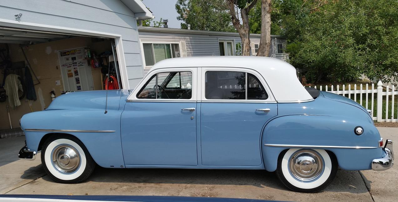
my 51 cranbrook has a 5/16-18 thread for the shift knob and the turn signal is molded or pressed on and can not be removed with out destroying the knob. Andy Burnbaum has a 3/8-16 shift knob that with a glob of silicon can be made to fit