
Merle Coggins
-
Posts
9,400 -
Joined
-
Last visited
-
Days Won
87
Everything posted by Merle Coggins
-
Ahh... I read that but didn't fully understand the reference. I now also see the yellow plug where it will connect.
-
No brake line to the left wheel?
-

19** Dodge Ambulance Australia - Vehicle Check
Merle Coggins replied to The New Guy's topic in Mopar Flathead Truck Forum
In North America that would be a 1948-1950 B-Series truck. But in Australia they changed model designs in different years, so it could be a later model. Hopefully some of our Aussie members will chime in soon to help you out. -
Once you get past Speed 9 bad things will happen and you'll end up at Speed 0 again. ?
-
Take a piece of rope and pass it through the seat, where the seat belt will come through on your right side, until it reaches your planned anchor point. Then sit in the seat and put the rope over your lap and route it to your other anchor point. Mark the rope, remove it, and measure the length.
-
218 engine noise at higher rpm's
Merle Coggins replied to WPVT's topic in Mopar Flathead Truck Forum
I've done a few trips with my truck where I ran a sustained 3000-3500 RPM for several hours without issue. But I also know the condition of my engine as I built it. I agree with Jeff. A few years ago I started experiencing detonation "ping" at higher RPM under load. It did have a bit of a "clatter" sound. I kept telling myself, "One of these days I'll get around to investigating it". Eventually it knocked the electrode center out of a couple of spark plugs causing a serious loss of power. I found that I had a bad vacuum advance causing a vacuum leak, which likely leaned out my air/fuel mixture leading to the 'pinging'. After replacing the vacuum advance and spark plugs, and adjusting the valves, all runs good again. In hind sight it could have been much worse than a couple of failed spark plugs. You can damage pistons, wrist pin bushings, and/or con rod bearings due to continued operation with serious detonation. -
Need a gas replacement gas tank
Merle Coggins replied to Rodney_Hamon's topic in Mopar Flathead Truck Forum
When I was making new brake lines for my truck I needed to make a loop in the line coming out of the master cylinder. I found a piece of heavy pipe with the proper outer diameter. I clamped it in a vice and gently wrapped the brake line around the pipe by hand. It turned out much better than I expected. -
218 engine noise at higher rpm's
Merle Coggins replied to WPVT's topic in Mopar Flathead Truck Forum
@wagoneer, There’s a flaw in your calculations… Your need to use total tire hight/diameter, not rim size. The best way to find that dimension it is to measure from the ground to the center of the axle and double it. You’ll likely find that your number will be closer to 28-30 inches. Also, I wouldn’t want to spin a flathead up to 4000 RPM. I don’t like pushing mine past 3500. Where did you find the 4000 RPM redline number? I’ve never seen a published spec for that. -
If you continue to ignore it the oil leak will eventually stop (when it runs out of oil) ??
-
218 engine noise at higher rpm's
Merle Coggins replied to WPVT's topic in Mopar Flathead Truck Forum
I'd be concerned that it is detonation at higher RPM under load. What is your ignition timing set to? -
Here you go...

-
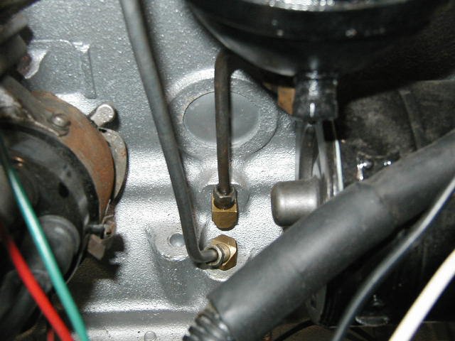
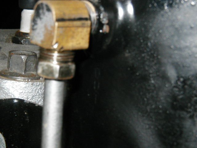
Here's a better view of the fittings in the block, showing the 45 degree elbow on the return side. Like Ken stated, different filter designs have different flow directions. My filter is clearly stamped OUT at the upper port, and that is the one I have plumbed to the return port in the block.
-
wally’s 1948 B1FA-152 thread
Merle Coggins replied to wallytoo's topic in Mopar Flathead Truck Forum
Good job... Might want to get in there again and recheck the torque on the nuts. I've found that after a few heat cycles they sometimes loosen up a bit. I'd hate to see you blow out another gasket because it loosened up on you over time. -
Old Cars Weekly Truck story
Merle Coggins replied to plymouthcranbrook's topic in Mopar Flathead Truck Forum
Could it be a trailer brake controller? -
Looks right to me. Also looks like you have a longer starter than I do.
-
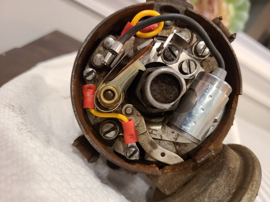
You may need to do some continuity tests with an ohm meter. That top coiled yellow wire should be what connects to your coil. Check that it is not grounded out to the distributor case. That wire, the condenser wire, and the points conductor strap should all be connected at that screw. I believe you said you corrected the points conductor from this picture. When the points are open there should be no continuity from that terminal to the distributor case (ground) When the points are closed there should be continuity between the terminal and the case. This will confirm that the points are working. If you suspect that the condenser may be grounding things out, you can disconnect the condenser wire and retest. The lower yellow wire should be providing a ground between the floating points plate and the main body of the distributor. It looks like it should be good, but you can check the continuity there too.
-
Some distributors are reversed from others for what ever reason. Thus the need for different internal parts and the need to identify them by your distributor number. Once again, I suggest you double check/set our points gap with the rub block sitting on the peak of the cam lobe, as shown in Sniper’s picture. Your earlier picture showed the gap extremely wide. I suspect the gap was inadvertently set initially with the rub block on the flat part of the lobe, when they should be closed.
-
Yes. It was built by Austin for Nash/AMC. It has an Austin 1500cc engine.
-
Almost looks like an oversize version of my wife's Metropolitan. ?
-
Interesting photos I have run across.
Merle Coggins replied to Don Coatney's topic in Off Topic (OT)
Looks like the road is blocked... -
Help! Where to Stop? 1951 Dodge P/U Restoration
Merle Coggins replied to Julie's topic in Mopar Flathead Truck Forum
Just sent me a message with the Private Message feature of the forum. -
Yes, the pitman arm needs to be clocked correctly on the shaft. A couple of center punch marks will help with realignment when reinstalling. And you’ll need a pitman arm puller to get it off.
-
8 hole cranks do not have symmetric holes either. There is one that is slightly off from the rest so that my Fluid Drive would only go on one way.
-
Help with a wiggling P12 lower pulley
Merle Coggins replied to capecodcaper's topic in P15-D24 Forum
That looks like a standard pulley. There are a couple different size hand crank nuts, but as Andy mentioned you will need a rather large socket. There will be 2 puller holes. One can be seen in your photo. Be careful when threading in the bolts for your puller. It's very easy to thread them into the front cover / seal. You'll likely want to replace the seal anyway once you have the pulley off, but you don't want to damage the front cover in the process. It might be tight quarters in there for a puller without pulling out the radiator. -
Did you set that gap with the points on the tip of the lobe, as shown in the picture, or with the points rub block down on the flat part of the cam? If you were adjusting with the points resting on the flat part that would explain the large looking gap now with it up on the lobe. If that's the case the points will never close to activate the coil. Recheck your points gap with the points rub block resting on the very tip of the cam lobe.