DonaldSmith
-
Posts
2,471 -
Joined
-
Last visited
-
Days Won
25
Content Type
Links Directory
Profiles
Articles
Forums
Downloads
Store
Gallery
Blogs
Events
Everything posted by DonaldSmith
-

horn, horn ring, part info needed, 1948
DonaldSmith replied to Bern Pearson's topic in P15-D24 Forum
The horn wire goes through the steering shaft and exits at the bottom of the steering gear box, where the wire connects to the wire going to the horn relay. Disconnect the wires to check the grounding circuit in the steering shaft and the relay circuit the powers the horns. This should show which part of the circuit has the problem Get a test light with long leads. Connect one lead to a power source, and the other lead to the wire from the gearbox. With the light visible in the cabin, you can fiddle with the horn ring assembly and see what lights the light. To test the horns and their relay, briefly ground the wire that goes to the horn relay. (Plug your ears.) The horns should sound or at least the relay should click. You may have to have the key at IGN to power the horn circuit. -
horn, horn ring, part info needed, 1948
DonaldSmith replied to Bern Pearson's topic in P15-D24 Forum
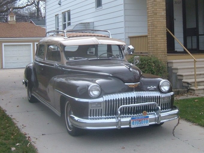
I don't know what parts would be called an actuator or a switch. The whole assembly acts as the switch. I don't know what the parts diagrams call these parts. Here's my horn ring, for a '47 DeSoto. The design would be somewhat different from the other Chrysler products, but the same principle. (Cars with horn buttons would work completely differently.) In the center, one can see the end of the horn wire and the brass thingie that spans across the spring. This thingie bolts to the plastic wheel, and is insulated from ground. Covering the thingie is the tee-shaped part of the horn ring assembly. This big tee does the work, with its lugs always pushing back the big spring. The ends of the tee connect to the ring itself; two ends actually go through the cross bar of the wheel. The whole horn ring assembly is isolated from ground. Out of curiosity, I touched the horn wing with a grounded wire, and it completed the horn circuit. (I had a light hooked up instead of the horns- easier to work on the circuit - no blaring horns.) Then I pushed the horn ring in evenly, pushing all the lugs against the spring, and there was no light. Push the horn ring, and the opposite end pulls away from the spring, allowing the spring to ground against the brass thingie.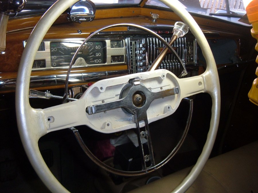
-
horn, horn ring, part info needed, 1948
DonaldSmith replied to Bern Pearson's topic in P15-D24 Forum
Short course on how the horn ring works. (The whole assembly is the switch.) The tee-shaped thing holds the end of the grounding wire for the horn relay. The spring is grounded. Without the horn ring in place, the horn would honk constantly. The horn ring is not grounded. It has tangs that push the spring away from the tee thing. In place and undisturbed, the horn ring keeps the horn from honking. Push the horn ring, and one or more tangs will pull away from the spring, allowing the spring to ground the tee thing. Experiment: Ground the horn ring; The horn should sound. Evenly push the entire horn ring, so that all the tangs are pushing the spring. The horn should not sound. That's all I have to say about that. -
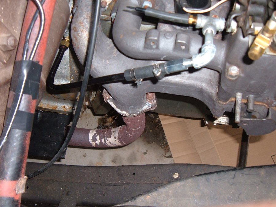
Here's a slightly better photo of where the vacuum port is: The vacuum gauge hose goes in place of the short hose with the end plug.
-
Here is my setup, for the nefarious vacuum gauge and for the PCV system: (The port is on the intake manifold, just below the carburetor.)
-Copy.JPG.b5bd2c81a23d31834a326d19a95d079f.JPG)
-Copy.JPG.5fead87d5fad5c132a7ee5218d3dda1c.JPG)
-
My vacuum gauge is somewhat permanently attached to the cowl with magnets, between the hood hinge and the heater hoses. That leads me to a naughty trick at car shows. I'll look under the hood of my car like a stranger gawking at the engine. Reaching for the vacuum gauge, I'll say, "What's this?" and dislodge the vacuum gauge. Juggling the gauge in my hands, I'll act flustered. Then I'll tell the onlookers that it was OK, I'm the owner of the car. I know, I'm bad.
-
A car with a vinyl coating like that car would be less likely to be stolen. You could have a lush interior, and all sorts of luxury features, and still be able to park it in a bad neighborhood.
-
Australia is upside down from us. If you turn the car upside down, the brake booster will be on the left side. Makes sense?
-
The horn ring is counterintuitive (it doesn't work like you would think). I went through this some time ago with my DeSoto horn ring. (Some ambitious and savvy person could look this up.) The gizmo, in this case the "Y" shaped bridge that holds the spring in place, is isolated from ground. The horn wire attaches to the middle of the gizmo. The spring is grounded. As pictured without the horn ring, the gizmo would be grounded by the spring, completing the ground circuit to the horn relay. Constant Honk! The horn ring is isolated, and in normal position its lugs push the spring away from the gizmo. Push the horn ring, and one of its lugs pulls away from the spring, allowing the spring to contact the gizmo. Honk!
-
Confirming the coil wiring for a 47 DeSoto with the semi-automatic transmission. Coil Negative post: (Hot side) Red wire from "coil" post of ignition switch, and green wire to "Bat" terminal of the transmission relay. Coil Positive post: (Positive Ground system) Black wire to "PRI" post of transmission relay, and black wire to distributor. So, the negative post takes power from the ignition switch and provides power to the transmission relay. The positive post takes the timed grounding from the distributor to energize the coil, and the other wire grounds the coil during kickdown, to briefly slow the engine, so the transmission can do its wonders.
-
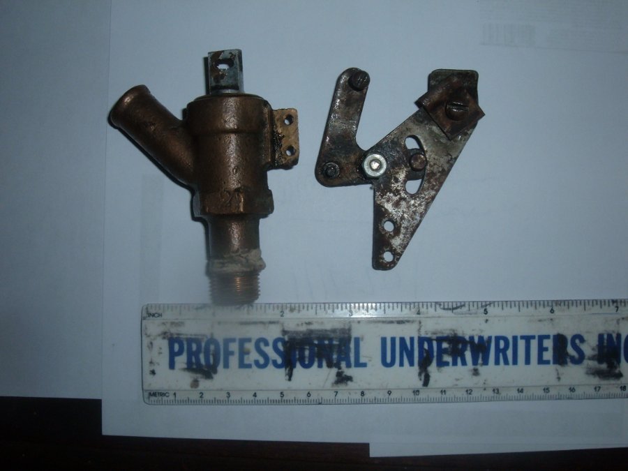
Here's the heater valve on my '47 DeSoto: The bellcrank pulls the valve open as the knob is pulled. The two little holes in the bellcrank assembly correspond to the two little holes in the body of the valve.
-
typo: primed, not rimed
-
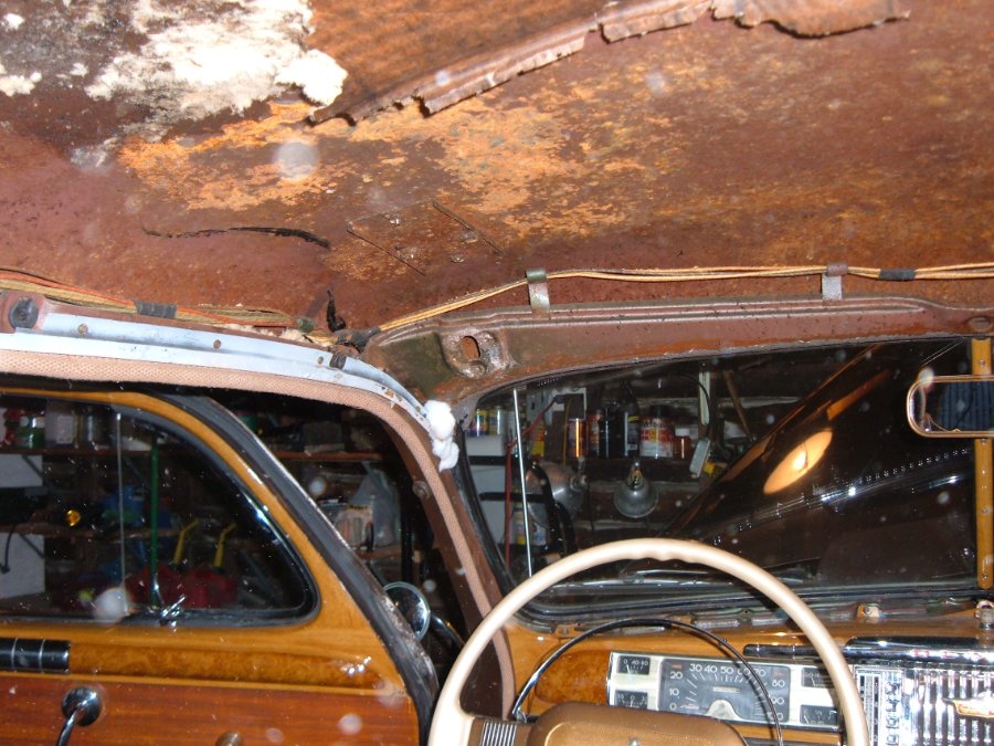
There are metal strips with teeth on the hidden side, to catch the headliner material. This photo shows the metal strips, which I removed, rimed and reinstalled (back in 2007). It's a bit tricky to disengage the existing headliner from these teeth. The bottom of the metal strips can be bent out a bit, and something used to push the edges of the headliner free from the points of the teeth.
-
Was the engine at TDC when the dizzy was removed? If not, "7:00" doesn't apply. Before removing the dizzy, keep track of where the rotor points, and put the dizzy back the same. Too late? Don't know? Then the fun begins. Find TDC of the compression stroke (Thumb over the spark plug hole works well). The rotor should point to the corresponding plug wire for No. 1 cylinder. If no one screwed up, that will be at the 7:00 position. People have lived with unorthodox arrangements, just so the rotor points to the No. 1 plug wire when that cylinder is at the top of its compression stroke. That's all I have to say about that.
-
My First Car -- P15 1947 Plymouth Deluxe
DonaldSmith replied to NickPickToo's topic in P15-D24 Forum
The must have had a real powerful stapler that pierced the metal in the process. I used real small screws to put in my fuzzies. But that was in distant memory, and before I had a digital camera to memorialize processes. -
Jiffy Jet - these are posted somewhere else, but here goes: (The thicker hose goes to the foot-operated pump under the floor. The thinner hose goes to the tubing at the dashboard.
.JPG.c15869e08a081c1986b007898f1ea149.JPG)
.JPG.8f7c42b7d3024cfa62d9bc5d48285282.JPG)
-
Jiffy Jet going in.
.JPG.e023288fa2ed8c48721c8e18b91fae32.JPG)
-
Yesterday was not too bad, cool but dry. We raked and blew some leaves to the street, and I thought I would sneak in one last drive of the year. Slow cranking; loose cable clamp. Battery charger. Shot of starter fluid. Car started, but quit when I let off the gas. More battery charger, another shot. Kept foot on the gas for a while. Headed down the drive, giving it gas to keep it running. Let it idle and warm up. Took a photo, saved photo under "Glamour shots" folder. Headed out. Not running right; using the clutch at stops, afraid to the Fluid Drive would stall it. Went around the block, and back to the garage. This isn't fun anymore. Maybe the loss of car shows this year, and an abbreviated, unofficial. Woodward DreamCruise. Maybe too many chronic aches and pains. Recently replaced the manifold gaskets, a major job for me, to no apparent audible difference. Wondering what it takes to get this car running sweet again, for the rare times it would run sweet. Too many bad memories of flatbed returns home. I'm editing documents on History of my Ownership, Maintenance, and Improvements to My DeSoto. Maybe you can see where I'm going. Someday, I or my survivors will sell the car. We'll see how I feel, come Spring. Meantime, I can lurk on the forum, and vicariously participate in all the wonderful adventures with these old Mopars.
-
The oil filler cap has an opening with mesh filter, to let air into the crankcase. The opening faces away from the front of the car, so as not to force the air into the crankcase. The draft tube, hanging down on the other side of the engine, allows air and fumes to get out of the crankcase. The end of the tube is beveled, so that the passing wind will suck, or draw, the fumes out.
-
To RNR: My mother's folks lived near Welland, Ontario, and once a year we visited them. As a kid, I had little exposure to the exchange rate, but the Imperial Gallon of milk was one U.S. quart larger than the U.S. gallon. The paper jugs were cone-shaped. Nabisco Shredded Wheat boxes were squat, and had an image of the Niagara Falls on them. Crystal Beach: Yes, we would get there, too.
-
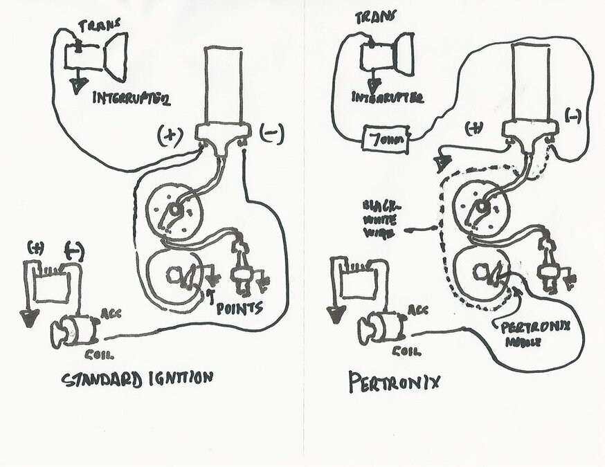
Have you called Pertronix for technical information? I did, when I installed their system five years ago. Other posts are covering this. See my wiring diagram. You need a resistor in the interrupter circuit. Pertronix calls for a 7 ohm, 5 watt resistor. But 12.5 watts is OK.
-
I'm so old, that if I see a penny dime on the ground, I'll pick it up. (They got rid of pennies in Canada. They should sell them all to us. We used to circulate Canadian pennies with our 'Merican change, without regard to the exchange rate. That's when we used to handle cash. Now everything is hand sanitizer and credit card. )
-
Pertronix - No dreaded points, condenser, etc. Running fine for 5 years. Lingering fear of sudden Pertronix failure, perhaps rare but sometimes reported. But with these cars, anything can bite us. Then there's lightning, meteors, etc. Tools for an extended cruise - cell phone, contact number for tow truck service, and credit card.
-
Manifolds apart. Gap instead of gasket: Got the 4 bolts out.
gasketgone-resized.JPG.9ca62389342ad855327d454ca446c2bc.JPG)
-resized.JPG.9556533154bbab362e374f482f08f1fa.JPG)
-
The resistor did not come with the Pertronix stuff. I will have to look into my records for a source. Maybe tomorrow. Yes, run the ground wire from the coil to any good ground. 8-26-2020: Breaking news: I checked my records from 5 years ago, when I installed the Pertronix ignition module. Pertronix called for a 7-ohm, 5-watt resistor. I called their technical gurus and asked if 12.5-watt would be OK. Yes. (I got resister RH0107R000FC02, 12.5 watt, 7 ohm, 1%, from Mouser Electronics. Less than 10 bucks, including shipping.