-
Posts
2,561 -
Joined
-
Last visited
-
Days Won
83
Everything posted by Sam Buchanan
-
Redneck exhaust cutout....
-
I think that means "he is on vacation"........ ? The page says he will be back today, 5/14.
-
https://p15-d24.com/topic/51306-new-dash-light-bulbs-bright/ Looks like the bulbs are still available. https://www.ebay.com/itm/Plymouth-1946-1947-1948-extra-bright-tail-light-bulb-63-replacement-6-volt-63/161410757417?ssPageName=STRK%3AMEBIDX%3AIT&_trksid=p2060353.m1438.l2649
-
Ok...you just validated how you should approach your "new" car so you can enjoy it with minimal cost. Don't over think this. The old Mopars are very well designed and once returned to serviceable condition are very capable drivers. Drivability doesn't require replacing the rear end, driveshaft, brakes or make the other mods you have been reading about. Just fix what you have and enjoy the car.
-

Vendor not refunding core charge; Resolved
Sam Buchanan replied to Sam Buchanan's topic in P15-D24 Forum
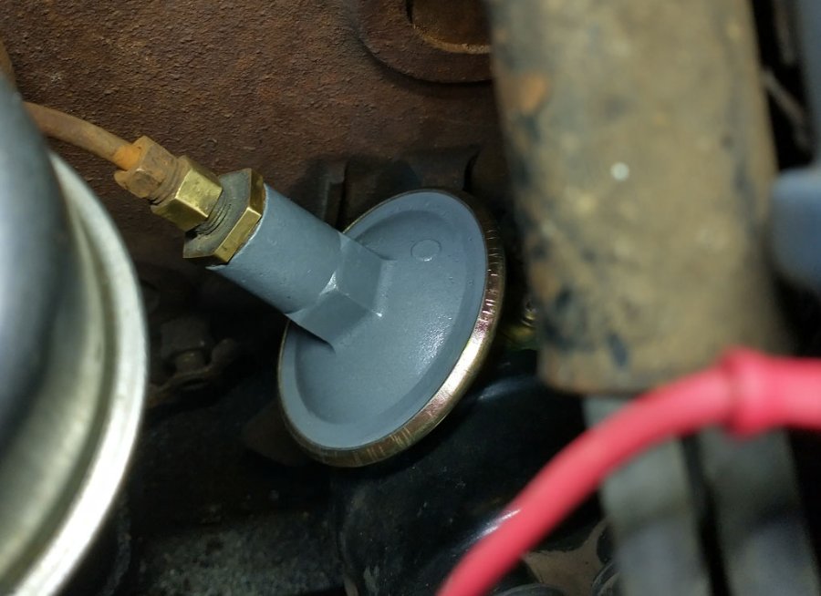
I saw a NOS vacuum advance on eBay, too. But I was concerned about the condition of the 75 year-old rubber diaphragm and the asking price was over twice what the rebuilt unit cost. The rebuilt I received really looks good, I suspect the can is a new part and everything is nicely replated. -

Vendor not refunding core charge; Resolved
Sam Buchanan replied to Sam Buchanan's topic in P15-D24 Forum
How much does Terrell charge for rebuilding one of our vacuum units? I found some comments in forums from a few years ago where members had used Terrell and the cost was more than what I ended up paying. Trying to uncrimp the vacuum can in a way so it could be reused, fabricating a diaphragm that has the same vacuum response as the an original unit, building a stamping die to recrimp the used can with a press, and replating all the parts prior to assembly.......naw......not worth $85 to me. Los_Control, how do you know the core I returned was an original part? And that the rebuild I received was from off-shore? It might have been rebuilt by Terrell. This thread has gotten ridiculous.....but entertaining. -
-

Vendor not refunding core charge; Resolved
Sam Buchanan replied to Sam Buchanan's topic in P15-D24 Forum
Man....I wish I was half the mechanic you guys are............................. -

Vendor not refunding core charge; Resolved
Sam Buchanan replied to Sam Buchanan's topic in P15-D24 Forum
Ok.....so how do you propose to rebuild a vacuum advance unit?? You do exactly as I did, send in your old one and get a rebuilt one back. As far as I know there are no new ones available. Let's think before we post....... ? -

Vendor not refunding core charge; Resolved
Sam Buchanan replied to Sam Buchanan's topic in P15-D24 Forum
Update: I forwarded the above message to AB and received a reply from Chris within an hour. Apologies were offered for the tardy service and explanations given (I won't go into that). AB sent me a credit statement that indicates the bankcard credit should be forthcoming. I will consider this matter closed provided the credit appears on my bankcard account in a timely manner. Andy Bernbaum has been a reliable vendor for me for four years and I assume that will continue to be the case. I appreciate their prompt attention to this matter today, just wish it hadn't been necessary to follow-up several weeks after the fact. Update: Credit has been received, case closed. -
This is not an attempt at vendor bashing but just a heads up to inform the community. I purchased a rebuilt vacuum advance unit from Andy Bernbaum for my P15 and it arrived a few days after placing the order. The price included $30 which was to be refunded when I returned the old unit as a core. The old unit was shipped back to AB the same day I received the rebuilt advance and tracking indicated the core arrived at AB three days later. Ten days after AB received the core the $30 charge had not appeared on my bank card. I sent a web message indicating I had not yet received the refund. Fourteen days after AB received the core I still hadn't gotten the refund so I called and was told the refund was on its way. It is now over three weeks after AB received the core and still no refund. It is just $30 but the non-return of the refund, intentional or otherwise, indicates to me either a lack of interest in customer service, a breakdown of internal procedures, or something more serious. I have purchased a lot of merchandise from Andy Bernbaum and their ebay store but this is giving me pause about further purchases. I still hope this will be resolved and will not hesitate to update if that occurs because I have no desire to treat one of our vendors unfairly.
-
Not a way to service the vacuum unit, there is a diaphragm inside that will develop a leak and not hold vacuum. However, there is a spring inside it that can be easily removed, you might see if it has seized. The device can be checked by pulling a vacuum on it (orally or with a pump) to see if the arm moves and stays in position. But if you hear air moving through it the unit is done.
-
Agree. Probably defective battery and charging system due to either defective components or wiring problems. Need to spend some quality time with a multimeter.
-
Bottom photo; The vacuum advance line attaches at the square-headed pipe plug on the carb base. A reverse flare fitting goes where the plug is located. But most likely your advance unit is defective due to old age.
-

Looking For Feedback On Tanks Inc Replacement Fuel Tank
Sam Buchanan replied to YukonJack's topic in P15-D24 Forum
Here is the tank in my '48 Plymouth: https://vansauto.com/product/41-48-dodge-plymouth-desoto-chrysler-6-cylinder-gas-tank/ It is about as exact a fit as the original as you can most likely find. It doesn't have the built-in sump filter which is a good thing. -
As a short-term fix slip some heat shrink tubing over them.
-
She'll run. Current thread about readily available spark plugs: https://p15-d24.com/topic/59840-autolite-sparkplugs-295-at-walmart-for-only-197-each-replacement-for-champion-j8c/
-

...back off piston by turning engine with fan.
Sam Buchanan replied to DonaldSmith's topic in P15-D24 Forum
I hate spinach........ -
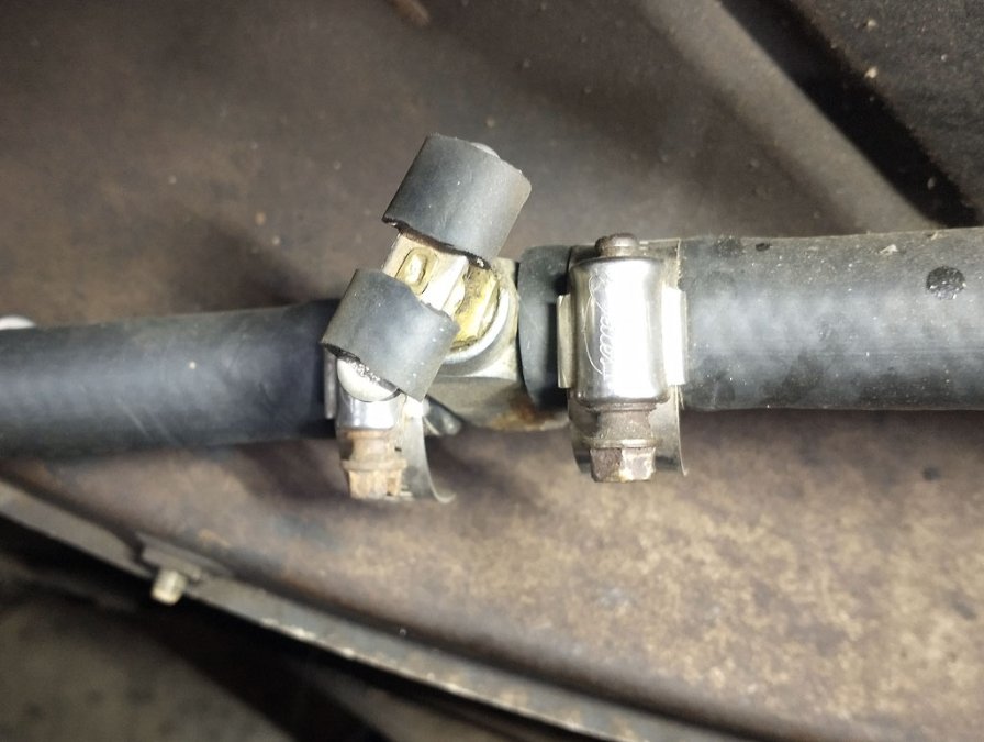
Another option is to put a valve in the heater hose. The on/off valve on the aft end of the head of my P15 was stuck open and I didn't want to risk it breaking off in the head if I tried to replace it. There are cable operated valves that install inline like this one but I haven't found that upgrade necessary, I just open and close the valve a couple of times per year when seasons change.
-
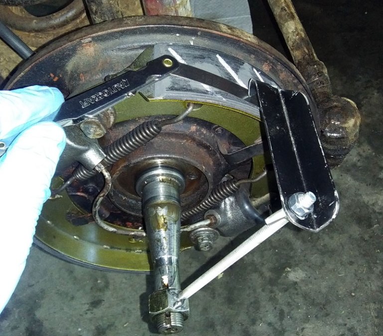
The reason the heels need to be adjusted so they very lightly contact the drum is so there is a base reference that gets the adjustment tool very close to drum diameter. Without this step you won't know how to set the adjusting tool. Once the heels are set, remove the drum and adjust the toes so they are within 0.006" of the heel. Then reinstall the drum, adjust the heels to barely remove any drag and adjust the toes if necessary to where they almost drag. The locking nuts on the heel adjusters need to to securely tightened, you can remove the drum for this once the brakes are adjusted. Then recheck after putting everything back together. This will get you very close to a satisfactory adjustment, readjust as necessary after putting some miles on the brakes. After doing this a couple of times you can leave the 0.006" gauge in the toolbox....you'll be able to do this by touch.
-
The 0.006" clearance is measured with the brake adjustment tool prior to installing the drum. The Miller tool, which very few of us have, allows a precise measurement of the drum ID compared to the OD of the shoes. Without that tool, we are left with using our simple little tool to insure the shoes are concentric within 0.006" after setting the heel of the shoes to lightly contact the drum. This is a workaround that usually results in satisfactory brake function.
-
Same here along with kitchen scrub pads from the same store.
-
Four (or eight) more pieces of 4x4 for stages and they have some adjustability and are still very secure. I realize people have been working under ratcheting jack stands for a long time, guess I've just gotten a lot less fond of them as my risk assessment changes with the advancing personal odometer.


