

Sniper
-
Posts
6,291 -
Joined
-
Last visited
-
Days Won
141
Content Type
Links Directory
Profiles
Articles
Forums
Downloads
Store
Gallery
Blogs
Events
Everything posted by Sniper
-
There is no perfect sealed system, stuff leaks. the residual pressure valves will leak by over time.
-
I do not know the intricacies of a generator's regulator setup. I do know that on the alternator's setup the VR has to be capable of handling the field current of the alternator. I assume something similar in a generator setup. But as with anything, input determines output. You aren't going to need that extra amperage if the load for it is not there so a fuse protecting it is probably a good idea.
-
We can argue semantics, but any increased resistance in a circuit is a load increase. Total voltage drop will remain the same, current drop across EACH source of resistance will change in the circuit as unwanted resistance will consume it's share of current. Remember V=IR So, as the unwanted sources of resistance consumes it's share of current, in the circuit, less is available to the wanted sources. The ammeter will increase it's output because it is voltage regulated, not current regulated. So until you hit the upper limit of the alternator's output it will overcome. That's what gives you the dim lights at idle symptom. My 65 Cuda had that issue, till I cleaned up all the connections and it went away. Original style mechanically regulated setup. Now you can see the headlights flicker as the mechanical regulator cycles on/off but the lights do not go dim. Not sure why you bring up starting, the charging system is not involved except indirectly insomuch as it is what keeps the battery charged. Being that the starter is the biggest load on in the system any unwanted resistance's effect in the starting circuit is magnified and will negatively effect starting. But that isn't part of the charging system and has no effect on how the charging system works except for the drain on the battery that needs to be replenished after starting is complete and that is matter of increasing the amount of time it will take to recharge the battery.
-
I am going to play Captain Obvious here and add to Kilgore's post. If the vent is not clear, pressure can build up inside the axle housing forcing stuff out the ends of the axle tubes, right on your brake shoes.
-
I went thru my parts book, if goes uo to 54. Seems those shims fit a lot of our stuff.

-
R10 12v http://site:p15-d24.com Copy and paste into your browser
-
Thanks for the follow up, may it help someone in the future
-
You have the vertical height to use one of Harbor Freight's gantries. But they are kind of pricey for a one time use. Me? I would think about using an engine hoist to lift one end of the body, hold it up with sawhorses and cross pieces, then lift the other end of the body and support, roll the old frame out, then build a cradle to hold the body that has casters. Or think of a way to use the lift you already have.
-
I was wondering if it was carbon from the intake valves getting in there, but your ports look pretty clean. DI engine are known for carbon build up on the back side of the intake valves.
-
Problem is where is the other end of the hoist going to attach? I (over)built a gantry crane to handle my 230 engine. But I have a low ceiling in the shop and no commercial gantry would be short enough to work.
-
I wonder if that's impact damage or erosion? Many years ago I was fooling around with a Carter AFB on top of my 318 and I dropped the accelerator pump check ball into the intake. It made its way into one cylinder and I had a bunch of nice little round dents in the top of the piston. But I never did find that ball it must have blown out the exhaust eventually.
-
Nice to see you're making progress I look forward to watching the build
-
Vehicle?
-
I no longer have that ball and chain holding me back. It's amazing what I can afford now. DO NOT use this crazy idea,
-
Yes poor workmanship is why I pretty much do not let anybody work on my stuff anymore.
-
You know, I just read this so ....
-
Here it is
-
I feel the need, the need for speed. Sorry I'll always be a lead foot. I put about 50k miles a year on the work truck, company owned, GPS tracked, so I abide. But when I am in my own ride it's A fiery horse with the speed of light, a cloud of dust, and a hearty "Hi-yo, Silver, away!" Now I need to practice the best launch techniques, lol.
-

Creative electrical, need help holding in the smoke.
Sniper replied to Los_Control's topic in Off Topic (OT)
Glad you got it working. 13.2 volts is not an uncommon voltage to see. -
Creative electrical, need help holding in the smoke.
Sniper replied to Los_Control's topic in Off Topic (OT)
Yes, just so you know I drove up to Amarillo and back yesterday thinking about this the whole way and when I got home I dug up that paper and figured out what was going on. Good luck and let us know how it goes. -
Creative electrical, need help holding in the smoke.
Sniper replied to Los_Control's topic in Off Topic (OT)
You are a scallywag. 😄 You made me dig up the paper on the GM 10DN charging system and read thru it, bottom of the page. Some archaic terminology was used, but hey that's ok the Navy taught me electronics and it's tech was even more archaic in some cases (AN/SPS-10 radar). So I understood it, I think, lol. You have what Delco calls a Two-unit regulator with indicator lamp. This drawing shows how to wire it, EXCEPT #4 needs to go thru an idiot light and parallel resistor (no value given for the resistor) if you want an idiot light, otherwise nothing gets connected there and 2 gets the switched 12v. Number three should be wired to as close to the battery as possible. This is the wire that controls battery charge voltage and taking it off the BATT terminal at the alternator is less than ideal. Although an engineer or a theorist will tell you that both points are "electrically identical" reality says any connection or splice between the two will create resistance and cause an effect. Since this charging scheme is fairly primitive in reality I don't think it matters enough, in other words it's likely to be within the regulator's margin of error anyway. Unless it's a really crappy connection. 10DN with ammeter wiring (you can run this sans ammeter and no light) 10DN with light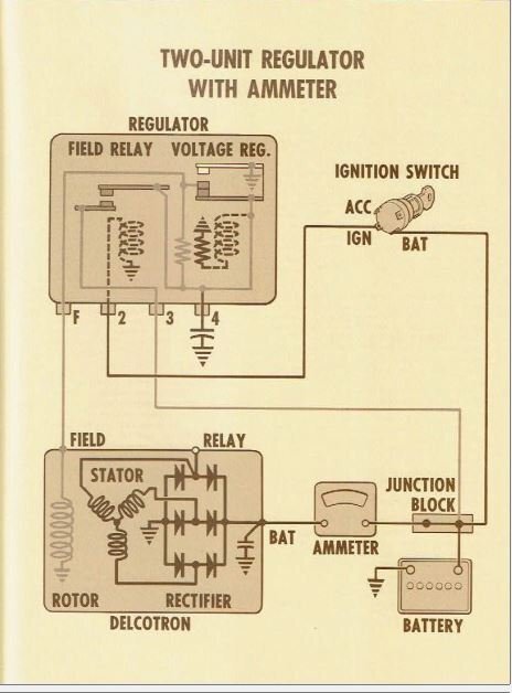

-
I'm glad you have time to Tinker. Work has been kicking my butt since before Thanksgiving. So whenever I have time off I'm either driving 5 hours East to visit family or recuperating from work. Last week I had to install and wire up 4,000 pounds worth of batteries all by myself. So needless to say I spent a lot of time recuperating this weekend. Getting old sucks
-
Creative electrical, need help holding in the smoke.
Sniper replied to Los_Control's topic in Off Topic (OT)
The major difference between a fuse and a fusible link is that a fusible link will tolerate an overload for longer than a fuse will. So if you have the occasional spike it won't blow. Since I do not know exactly how the GM charging system works I can't really say how much current that voltage sensing line uses. But I do not think it is directly involved in the field current necessary for the alternator to charge. I kind of suspect it's the on-off switch and something else handles the current the alternator requires to start charging -
Nice work
-
Creative electrical, need help holding in the smoke.
Sniper replied to Los_Control's topic in Off Topic (OT)
With the understanding that I don't do GM charging systems, I don't see a problem with that. Where are you going to put the fusible link?