HanksB3B Posted December 4, 2013 Author Report Posted December 4, 2013 Uh Oh...I didn't expect to be swimming the big fish. Just off the cuff the setup in the picture looks right. I will read and in the meantime hopefully somone that has one of those big boys will know the correct answer to your question. Thanks fro asking, Hank P.S. At least one B Series 1/2 ton guy says "Wow that sure is a lot of rusty crud in front of the radiator." Quote
HanksB3B Posted December 4, 2013 Author Report Posted December 4, 2013 (edited) I’ve been wondering about how those $100k 1955 Chevys with engines you could eat off, have perfect radius stainless steel or chrome fuel lines. I'm sure there are guys that it's part of their profession and there are probably some professional tools I don't know about. Earlier today I went to my electronics store searching for some heavy gauge wire to mock-up the fuel pump to fuel filter line. Of course they didn't have anything bigger that 16ga. but the word aluminum wire popped up in the conversation directing me to Ace Hardware. When I got to Ace somehow I spotted tubing and aluminum was very soft to bend and kept its shape. I bought 10' of it thinking I'll temporarily route the gas tank to fuel pump line. Once back at the truck I found out that what he sold me as 1/4" (I didn't think so) was actually 3/16" but as the luck of the Irish would have it, it slipped right into what will become the final 5/16" CN5 line. Flaring the aluminium tube allows a tube nut to be installed on the line. At first I hesitated cutting 36" off the 10' length because I mostly bought this to route the tank to fuel pump, but along the way I realized I could still use a connector with tube nuts either side to get my bendable aluminum line back to 10'. A thin wire inserted intot the inner tubing and then withdrawn should be a perfect measurement of where to cut the Copper Nickel CN5 line. I was hoping that “Three times is a charm" but came to the conclusion that 33 times is a charm and doing sit-ups under the truck is a whole lot cheaper than a gym membership. Today’s progress: When working on our trucks, knowing you'd get fired if this was a paying job is a good thing ! Thanks for looking, Hank Edited December 4, 2013 by HanksB3B Quote
RodFru2u Posted December 4, 2013 Report Posted December 4, 2013 Great looking Job Hank, Are you going to use a heat shield or are you far enough away to prevent vapor lock? Rod Quote
48Dodger Posted December 4, 2013 Report Posted December 4, 2013 This thread will go before the board of "National Executive Review of Dodge Schematics" and stamped with the offical seal upon its approval. Personally I will endorse the thread under the "Beau of Intelligent Thoughts and Cognitive Habits In Nerdom" Great work my friend. Tim aka 48Dodger Great news.....You've been accepted! You are now a member of the B.I.T.C.H.I.N. , N.E.R.D.S. 48D Quote
HanksB3B Posted December 4, 2013 Author Report Posted December 4, 2013 (edited) Great looking Job Hank, Are you going to use a heat shield or are you far enough away to prevent vapor lock? Rod Funny you should ask. I do believe I'm far enough away but I do not have a heat shield and want one. I've seen someone posted a drawing and I think VPW sells them but any leds would be great. My question is: With the route I followed is there room to install one or shouild I wait to finalize the line until I have one or does it look like there is adequate clearance. Thanks for asking, Hank P.S. Everyone knows it's just a mock-up right ? Great news.....You've been accepted! You are now a member of the B.I.T.C.H.I.N. , N.E.R.D.S. 48D Seeing as you are the Grand Poo-Ba...I accept ! Edited December 4, 2013 by HanksB3B Quote
ggdad1951 Posted December 4, 2013 Report Posted December 4, 2013 I did the heat shield drawing and have one around if you are wanting one Hank. I also have the joy(?) of my first job's requirement to bend tubing. I designed and built high end test equipment for my company and bent a LOT of tubing....mostly in TITANIUM! So tubing to me is easy and just using a piece of electrical wire gets me all I need to make complicated bends. Quote
Jeff Balazs Posted December 4, 2013 Report Posted December 4, 2013 Hank I have a shield you can have. I don't need it with the mods I made to my fuel system. Jeff Quote
HanksB3B Posted December 4, 2013 Author Report Posted December 4, 2013 I did the heat shield drawing and have one around if you are wanting one Hank. I also have the joy(?) of my first job's requirement to bend tubing. I designed and built high end test equipment for my company and bent a LOT of tubing....mostly in TITANIUM! So tubing to me is easy and just using a piece of electrical wire gets me all I need to make complicated bends. No wonder yours turned out so good. Do you think my tubing layout clears the heat shield ? Mark or anyone happen to have pictures of the heat shield installed on the truck ? (I'll do a forum search in the meantime) Thanks, Hank Quote
ggdad1951 Posted December 4, 2013 Report Posted December 4, 2013 here ya go Hank, I also have a few of the spacer studs left. 1 Quote
HanksB3B Posted December 4, 2013 Author Report Posted December 4, 2013 (edited) Looks correct to me I may be faced with more twisting and turning, It appears that the heat shield is more concerned with the fuel pump itself and not the line. Look hoiw closely (or exactly) Scruffy's pump to filter line in post #2 of his thread match this picture. John's to die for Masterpiece before it blew up (I was so bummed about that) what is that line from the block to the intake manifold ? Hank Edited December 4, 2013 by HanksB3B Quote
ggdad1951 Posted December 4, 2013 Report Posted December 4, 2013 (edited) Hank, originally my pump to carb was "factory prefect" but I modified it a bit to keep it away from the manifold a bit further and it pretty much looks like the one in John's blow up engine. I probably have it in a box some place in fact... Edited December 4, 2013 by ggdad1951 Quote
Young Ed Posted December 5, 2013 Report Posted December 5, 2013 I’ve been wondering about how those $100k 1955 Chevys with engines you could eat off, have perfect radius stainless steel or chrome fuel lines. I'm sure there are guys that it's part of their profession and there are probably some professional tools I don't know about. Hank Hank I believe they are buying premade lines. I think inlinetube is one company doing it. Quote
48Dodger Posted December 5, 2013 Report Posted December 5, 2013 Chevy?... The professional tool you speak of, is a checkbook. It has checks they write to the mopar guy down at the shop. lol 48D Quote
HanksB3B Posted December 5, 2013 Author Report Posted December 5, 2013 (edited) Well this guy won't be writing any BFC's to the Mopar Guys for no other reason than my truck has seen me have more money than time and more time than money. Guess what phase I'm in right now. Like they say your worst day under the truck is better than your best day at work. Edited December 5, 2013 by HanksB3B Quote
HanksB3B Posted December 5, 2013 Author Report Posted December 5, 2013 (edited) Edited December 5, 2013 by HanksB3B Quote
HanksB3B Posted December 5, 2013 Author Report Posted December 5, 2013 (edited) Edited December 5, 2013 by HanksB3B 1 Quote
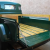
HanksB3B Posted December 5, 2013 Author Report Posted December 5, 2013 (edited) Just for kicks, at the end of the day, I followed my factory wrong gas tank to fuel pump line in 3/16" aluminum. The line crosses the driveline at what I think is a well protected area. With the addition of clips I think this might be a simplier installation. I know that Jeff (the man that never intends to show his truck) and others may say I'll loose points but honestly I don't think so and don't really care. Tomorrow I'll post the factory correct routing to compare notes. Thanks for looking, Hank (Dual Personality or is it Excessive Compulsive Hyperactivity Disorder) ECHD ? Edited December 5, 2013 by HanksB3B 1 Quote
Desotodav Posted December 5, 2013 Report Posted December 5, 2013 Nice work Hank. I wonder whether the original gas line to the tank was run to the left side of the truck to avoid heat from the exhaust?... or maybe for safety reasons to avoid the possible event of fuel contact with the exhaust? I recall messing around with old 1960's Ford (Mark 1) Cortina's in the paddock in my younger years - we called them 'bush-bashers' but I think you guys on that side of the pond call them 'beaters'. We had a couple of fires under the hood/s over the years from fuel lines breaking and spurting fuel on the exhaust - design fault?... who knows. Quote
ggdad1951 Posted December 5, 2013 Report Posted December 5, 2013 sorry Hank, I forgot to get pics, I promise to get them today. I think Davin is right, avoiding the hot exhaust is always a good idea.... Quote
Jeff Balazs Posted December 5, 2013 Report Posted December 5, 2013 Hank; As you know I am not adverse to making mods if there is something to be gained. In this instance I am not sure what you are gaining. The cross member you are using is a bolt in piece. It is designed that way for a reason. By attaching your fuel line to it you make it far more difficult to remove. Also almost all fuel systems avoid crossing over or under rotating equipment....like the drive shaft for obvious reasons. If you add in the fact that you are in close proximity and in fact are crossing a hot exhaust system you should have enough information to understand why the designers built it the way they did. Jeff Quote
Don Coatney Posted December 5, 2013 Report Posted December 5, 2013 Hank, Excellent report and excellent photos. Good job! You have educated many people with your report. Quote
TodFitch Posted December 5, 2013 Report Posted December 5, 2013 John's to die for Masterpiece before it blew up (I was so bummed about that) what is that line from the block to the intake manifold ? Hank Looks like a PCV system to me. I thought that the Mopar militarty PCV system plumbing ran outboard from the manifolds but this routing, even if not stock, looks very good to me. Quote
HanksB3B Posted December 5, 2013 Author Report Posted December 5, 2013 (edited) Thanks Don, likewise ! Actually your workmanship is always an inspiration to me and I'm sure to a lot of others ! Mark Thanks. Very clean and nice ! Hope mine turns out as well even though the routing is different. Next on the List: Mock-up the original Fuel Line path with 3/16 aluminum tubing. Two stage Mock-up of the Vacuum Line. First in aluminum, finalized in copper. Complete the Fuel Pump to Fuel Filter CN5 Fuel Line. Temporarily (unless someone makes my mind up otherwise) install the Fuel Tank so that I can move toward a permanent installation of the Fuel Tank To Pump fuel line. (read below) I think I'm going to install the Fuel Sending Unit in kind, as original, with no additional ground wire. I noticed that my tanks drain plug looks like it was serviced by the shop that boiled my tank out. The drain plug and surrounding area in rust free. Does anyone know the type and size tool used to remove what looks like a star fitting ? I cannot get a clean 10-90 ohm reading on either the restored or the new JC Whitney fuel sending unit. Both units show something going on when the float lever is actuated. My initial test was performed with an ohm meter connected to the wire terminal on the fuel sending unit and a ground wire to the mounting plate. With the ignition “ON” the fuel gauge failed to register. (I will try the same test with the JC Whitney unit) Keven?, Anybody: Please tell me what to look for (broken wire) or how to test the Fuel Gauge independently. Thinking out-loud, what would a schematic look like using with a power supply. I do have a six volt Eico power supply I use for radio repair. When installed and in operation, is the terminal of the fuel sending unit receiving 6V- and the mounting plate 6V+ ?. I'm thinking about doing something that may sound... well... kind of dumb. (I'm waiting Jeff) If I can’t solve the problem any other way, I'm thinking about filling the tank with water to test registration of the Fuel Gauge. You would think why not just install the JC Whitney unit. Well it's part of the satisfaction to get the original unit working (despite all the cork comments culminating in “put a cork in it”) The other part plain and simple laziness, as is looks like there is a considerable amount of work involved to make the one-size-fits-all JC Whitney unit . Filling the tank with gas is another option and hey if it works, I just need to replace the plug with the gas line tube nut, lower the truck off the jack stands and start-r-up. O.K. here’s the part where I In answer to Davin's "gas spilling on the exhaust pipe" This is a good point and duly noted. If I go with right side routing I would continue the CN5 hard line and flex line connection further away, and like the factory, directly adjacent to the fuel pump. My arguments: 1. A break in the line above exhaust manifold produces the same dangerous situation . 2. The factory fuel line is nestled into the frame directly below moving parts of the engine. This exposes the fuel line to potential damagefrom either a broken fan belt or worse a fan blade. The original driver’s side fuel line could have installed thru the radiator support. This would have offered better protection. This would require a connector on the left side of the radiator support in the event that you wanted to remove the front clip. Scruffy's "Roughy" Mark's "Museum Timepiece" 3. As Tim pointed out, running the line on the outside of the frame does “expose the fuel line”. I’d like to add that it’s now 60 some years after the fact and considering there are lots of trucks operating in excess of the 45-60 mph range they were originally designed for and there are lots of trucks (mine included) running aftermarket wheels and radial tires (ever see the wire bead whipping around in a blowout?) 4. Weakest argument “Who knows if back-in-the-day Detroit beancounters installed it that way with the assembly line as paramount Meanwhile back at the factory, looks like there is a lot going on here at the same time. You caqn see why they routed it to the outside of the rail. I'm sure the the guy to the extreme right ldoesn't feel lile diving into the mix with a 1 ton engine being lowered from hoist) Think he has any second thoughts about it? Nah... The precentage of any of these scenarios mentioned above is anyone's guess Probably the same percentage of running the gas line near the exhaust pipe. Jeff I know you are not adverse to making mods and good ones at that. Look at where the fuel line is under the fan belt rotating pulleys and the fan (argument #2 above). Please tell me if you think it might have been a better idea to run the line inside the left hand frame member and thru the radiator support (with a connector on the left side of course) Remember "You'll shoot your eye out" I rest my case. Do you agree or disagree with any of the above ? Kindly let me know thanks, Hank (shut up and get under the truck) Edited December 5, 2013 by HanksB3B Quote
Don Coatney Posted December 5, 2013 Report Posted December 5, 2013 here a go Hank: What head bolts are you using? Quote

Recommended Posts
Join the conversation
You can post now and register later. If you have an account, sign in now to post with your account.