thebeebe5
-
Posts
530 -
Joined
-
Last visited
-
Days Won
4
Content Type
Links Directory
Profiles
Articles
Forums
Downloads
Store
Gallery
Blogs
Events
Everything posted by thebeebe5
-

Voltage regulator interchangeablility (and other questions)
thebeebe5 replied to thebeebe5's topic in P15-D24 Forum
Ebay listings for the 4003 claim it covers 37-39 plymouth, 1940 dodge, fargo and various other makes right around the 37-40 range. I did just find this listing at mopar mall seeming to indicate it as a similar item or OE equivalent to my original.... Hadn’t seen this prior.... https://www.moparmall.com/853765-VRR-4003A-VRD-4002A-VRD-4002B-Regulator-p/868-019.htm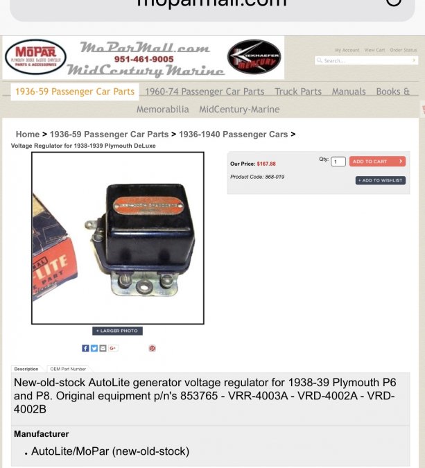
-
Voltage regulator interchangeablility (and other questions)
thebeebe5 replied to thebeebe5's topic in P15-D24 Forum
On my to-do list for sure, but in case it doesnmt clear the problem I’d like to know what replacement is viable. -
Anyone know if a VRD-4002-A regulator can be replaced by a VRR-4003-A regulator? I see listings online claiming the 4003 fits my '37 P4, but the 4002 is what's on it now. I'm having an issue with intermittent regulating. Needle goes to roughly 10 amps charge, then back to zero, and spends most of it's time on the zero... ? When I fired the car up after the year it took me to rebuild the engine it stuck on discharge and drained the battery without my being aware. A light tap freed up whatever point was stuck inside, but now I'm not regularly regulating....
-
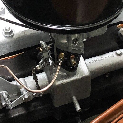
Port is 1/8” NPT. Get an inverted flare fitting and use a metal brake line or make up your own from your favorite suitable tubing.
-
-
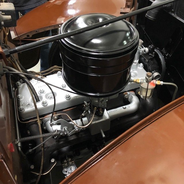
I’m just keeping it stock. The original ignition is lighting the fire, and the oil bath air cleaner suits me fine. Been running that filter on my old cars for years. They really don’t get lots of miles on them, and i avoid driving in dust storms around here. ??
-
I’m not sure why the step up jets would influence cruise AFR. If you’re running three carbs maybe there’s different spring rates for the springs between carbs? Just a guess... That jet should be closed while cruising. Vacuum should hold the plug down in that jet and block it off.
-
Who Is Actually Driving Their Vintage Mopars?
thebeebe5 replied to 55 Fargo's topic in P15-D24 Forum
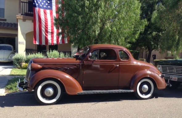
Thankfully i can now say I’m driving my vintage Mopar. One year of Saturdays rebuilding everything from the radiator to the differential and she’s roadworthy once again. Smooth as silk in fact....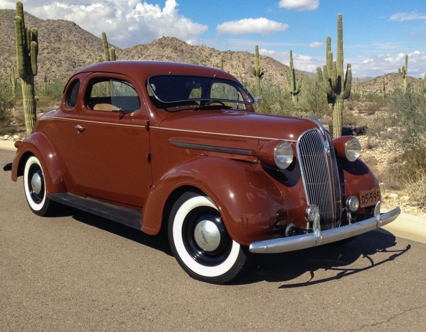
-
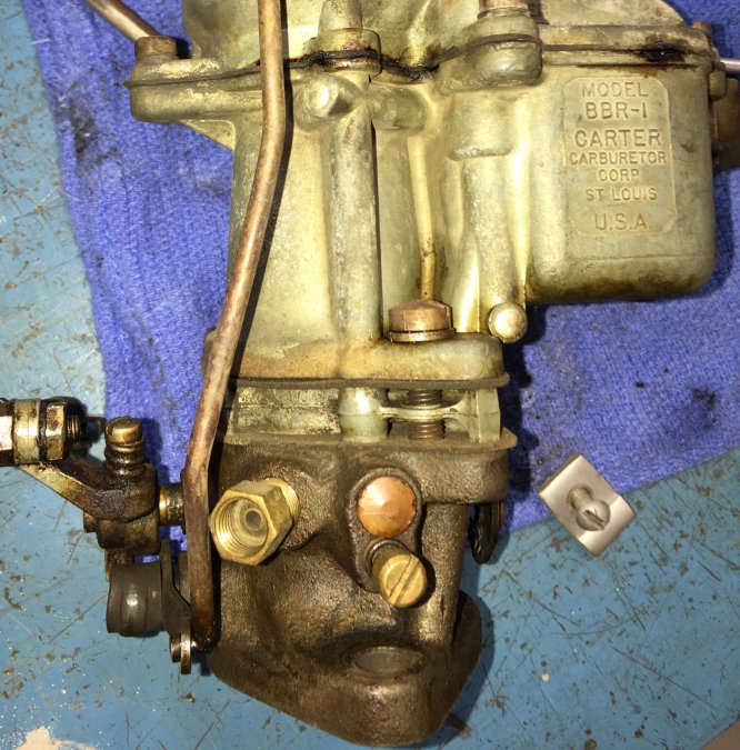
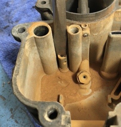
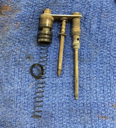
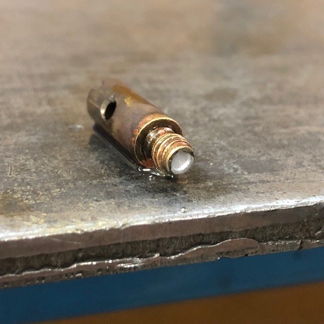
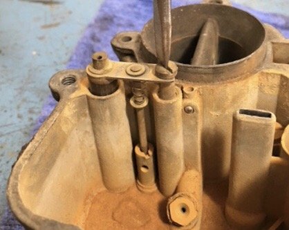
Fred, jets were obtained buying cheap “basket case” carbs off ebay and hoping the jets were still in place. Here’s what I did today. This carb is really basic. The power circuit (I believe they call it a “step up jet” in the manual) is controlled by this trident of brass gadgets seen here. A vacuum plunger, a “step up jet” plug and an idle circuit emulsion tube. Unscrew the idle circuit emulsion tube and lift the trio out. Under vacuum the plug in the middle of the group is held down tight into the step up jet keeping it closed to fuel flow. When the gas pedal is pushed down and vacuum drops the engine will want more fuel for a WOT run up to speed. The spring expands in the absence of vacuum (as during WOT) to allow fuel to flow through the step up jet thus providing the required fuel for rapid accelleration. That jet is being removed here. The main jet is screwed down in the bottom of the bowl just to the right of the step up jet. This is what it looks like. I had two different jets among the three carburetors I had available. In the carb the car came with was a 149-43S step up jet and an unmarked main jet. The step up jet had an orifice that measured 0.037”. I had a duplicate of this same jet and another marked 149-63S which measured 0.039”. The main jet was somewhere between 0.050 and 0.054” (all three I had were). A 0.050 drill bit dropped through it, but a 0.055” bit would not. It was close though, so I drilled it out easily by hand with the 0.055” bit. Figured I could go up a little at a time. Now the cruise AFR should be a little fatter, and my target was about 14.5:1 (down from around 15.2:1). BUT opening that jet would only add to the already too rich WOT AFR of 12.8:1. Remember, the main jet is still dumping fuel into the circuit when the step up jet opens in the absence of vacuum. So, I need a smaller step up jet.... But, I don’t have one. So I modified one of my extras. Got some 60/40 general purpose solder, some flux and a torch. The orifice of the step up jet is up where the plug makes contact. Below that the jet is wide open. I think I measured them all around 0.067”. I didn’t want to permanently modify the jet if I could help it, so I flowed some solder into the bottom of the jet only and kept it well away from the jet/plug interface. Then I made a mistake.... ? I make them often. With luck I learn from them.... I drilled down through the jet into the solder with a 0.029” drill bit chucked up in a tiny hand held chuck, but halfway through I realized the shavings were going to end up between the solder plug and the original orifice and clog it up. Easy fix, really.... just reflowed the solder and melted the shavings back into the solder plug, then redrilled. As far as leaner or richer jets, obviously larger holes in jets let more fuel pass through. What the wide band told us last week was that the WOT AFR was a bit rich and the cruise AFR was lean. The main jet is responsible for the cruise AFR and the two combined are responsible for WOT AFR. A smaller step up and a bigger main jet on the wide band gave these results: Cruise of 14.5:1 (perfect!) and WOT of 14.9:1. Remember I decreased the step up jet orifice by about 25%. Brian wanted to see WOT richer, so I pulled the plug, drilled it out to 0.033” and went for another spin. WOT was now 14.2:1 AFR. Still a tiny bit leaner than he wanted to see, so I went up to 0.034”. That should get it down in the high 13s. Tiny changes yielded significant results in this carb. Will run it tomorrow and check. I also tried to lean out the idle, but kept ending up with a lean misfire with AFRs above 12.1:1. So it will stay in the high 11s.

-
You’ll have to add a new rear main seal to get it to stop. Seal is dirt cheap, but the time and effort involved to install it is where you’ll pay. In all it’ll be less expensive than shares in your favorite oil stock, but will take less time than wiping up the mess time and tim again eventually. Depends on how long you can take slipping on the spill before you take the plunge. Save your $$ on additives. That’s pi-_ing in the wind...
-
??????
-
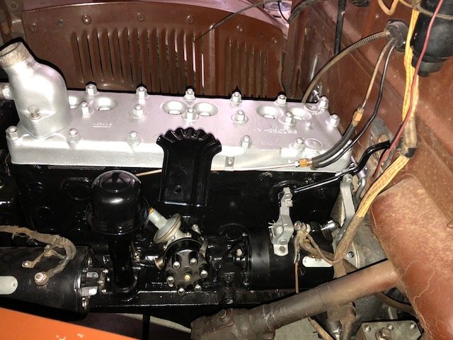
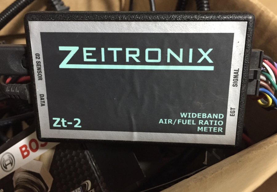
Retorqued the head again this afternoon. Gained a little bit more squish on that gasket.... When done we hooked up an O2 sensor to the bung we'd installed Saturday and went for a spin. Idle AFR was right at 11.3:1. A bit rich. I can fiddle with that a bit. When cold the car didn't like the screw touched though. We tried turning it in until we saw mid 12's, but the engine didn't sound as happy. WOT saw 12.8:1 and cruising was right at 15.2:1. If I can figure out a way to both add more main jet (easy...) and take away a touch of the power circuit I think I can get both of those numbers closer to the mid 13's. One thing I can say is this thing is really smooth. You know that Plymouth commercial where they set a glass of water on the fender? Well, I'm betting I can set it right on top of the air cleaner. It doesn't budge.
-
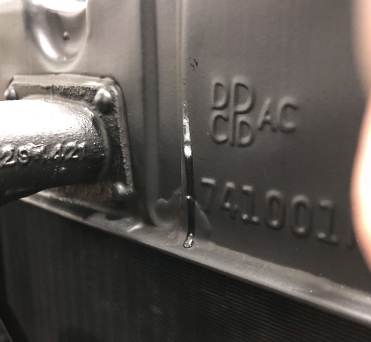
Noticed an unfortunate radiator leak Monday evening.... Seems to be weeping through the side of the upper tank. This is a disappointment...
-
I’ll get some better video (without me in it) with a GoPro this weekend. But here’s the first drive....
-
A timely question. Mine’s gtting a little long in the tooth as well. Was thinking about a replacement yesterday....
-
Getting down to the last for this build. At least I hope I am.... Retorqued the head yesterday. Marked random nuts and you can see they torqued well past their original location. That gasket still has some room to seat though as compression is still leaking at most studs. Also, adjusted clutch, hooked up E brake, found the carb top was a bit warped and sanded that flat, tweaked float adjustment etc etc. Just buttoning up in general. So far no oil or water leaks, and got 5miles on the ODO late yesterday. Sounding really good so far. Next week we’ll install a bung for a wideband O2 sensor and see just where the fuel mix is. Once the tune is complete I’ll drive it over to another friend’s shop and have a go at his chassis dyno. Will be interesting to see how close to the stock published HP it is now.
-
Sounds like it worked out. At the shop we drill them out to thin the walls and reduce the holding power of the guide in its bore, thrn either hammer them out with a jig made to fit the guide OR use an air hammer to drive them out.
-
Cool car. For images make a slight edit prior to uploading. Problem solved.
-
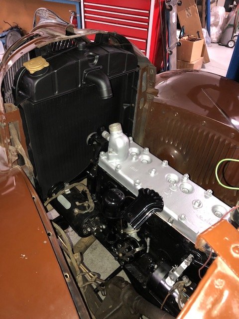
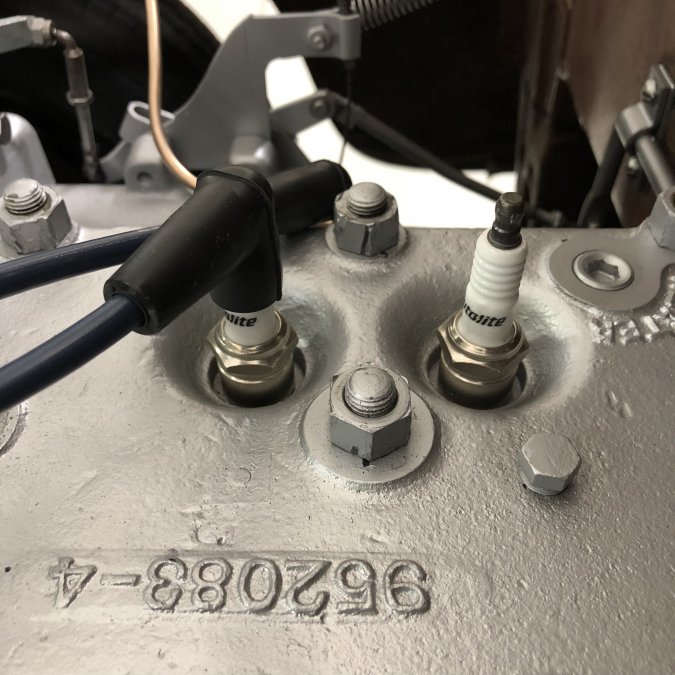
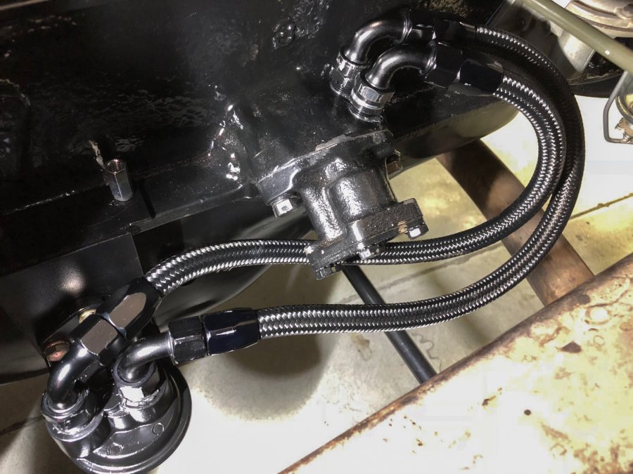
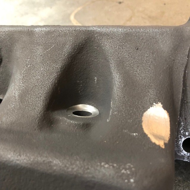
From memory (without reviewing what I wrote earlier!) in looking for a place on this old block there seemed only one logical spot.... the oil pump boss. Started out with 3/8”NPT fittings but upsized to 1/2” NPT for more flow. If I had to do it over again the only change I’d make is to make certain there was more separation between inlet and outlet holes OR that the outlet at least angled away from the inlet more to avoid having to machine the fittings like I did. Tapped the line with a (IIRC) 3/4” tap and tried to keep it so the plug I made (from 3/4” grade 8 bolt) would stop right between the out/in holes, but overshot slightly. When I screwed in the plug I dimpled the threads in several places as I screwed the plug home and added some red loctite to the threads as well. It’s not moving I don’t believe. At least not until someone wants it to. Should a future owner want it back to normal, remove plug and use 1/2” pipe plugs for the holes and it’s back to normal flow. But I can’t imagine it will ever get reversed.....
-
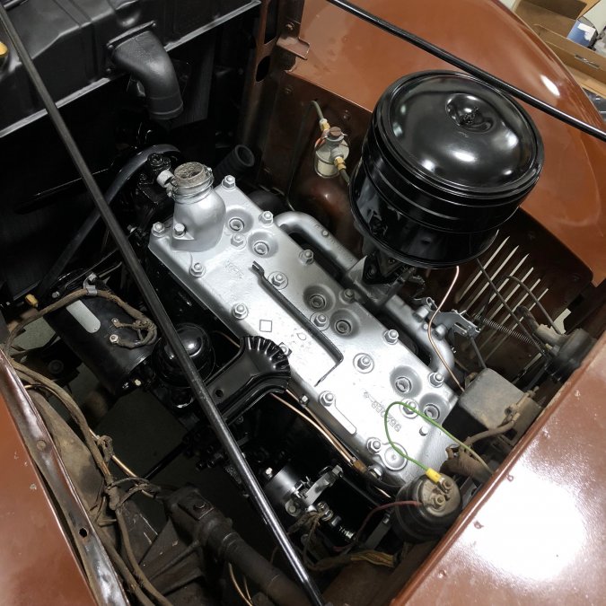
So, a long day yesterday, and the end being in sight I didn’t want to quit. Neither did my pal Brian who pitched in and ran errands in the evening to get the car started. In the am I got the radiator hoses on, bypass on and the oil adapter plumbed and painted. Filled up the radiator with distilled water, or at least started... when I found my first mistake of the day. I hadn’t tightened the water temp bulb in place and water was pouring out the back of the head. Sigh.... Also, I’d forgotten to tighten the plug I’d put in the bypass housing as I’m not replacing the useless heater line that was connected to the back of the head when I got the car. So, got that sorted out and topped it off. I figured if it was going to leak I’d fill it early and find the issue. Well, it did and I did. Also, got the air cleaner and breather decals on. Is there one on top for a ‘37...? I have a red and black “Chrysler” air cleaner decal that obviously goes on the top of something, but didn’t apply it. Made up a wire set and made my second mistake of the day. I’m not sure why I wasn’t thinking by 6pm, but I wasn’t. Wire set came with the plug ends installed and i threaded them and promptly clamped the wrong end of the cap terminals to the wire. I have extra terminal ends at home, but not at the shop. Figures. But Brian had a nice set of mix and match Ford metallic wires on the shelf from another build and we installed those for the start up. While I was screwing that up Brian ran out and got me a battery. Had tried to charge mine overnight but it didn’t take, and there wasn’t enough voltage to even turn the starter motor over without plugs to find the compression stroke for No1. Then, when he got back, he drained the year old gas from the tank (“I didn’t expect it to take a whole year, Brian”) so we could make an attempt. Wasn’t much over a dribble in there, so that worked out okay. First I left the plugs out and cranked the motor over to get oil pressure up. Installed plugs and cranked for a while and weren’t seeing gas in the fuel pump bowl. Brian gave the gas tank a bit of compressed air to assist, and within moments there was fuel up and into the pre carb filter. Tried to fire it again and it wanted to start, but wouldn’t quite. Took about four attempts to get it to catch and run, but it wouldn’t idle until the fast idle screw was adjusted, and then.... well, it purred. ? No smoke, no misfires, and one leak; just needed a 1/4 turn on the line at the fuel pump that feeds the carburetor to fix that. No oil leaks so far. No water leaks noted. DID notice some compression seeping at a few head studs though once it was warm. Not sure how significant that is or if a retorque post initial heat cycle will fix it. Hoping so.... Still haven’t driven it yet. It’s penned in by a later model Trans Am on the lift (between me and the door) that is getting fancy suspension installed and my car is too tall to get under it. Hopefully that project will be gone by next weekend and I’ll get a chance to drive and see how the new clutch and rebuilt transmission work out.
-
Finally. I’ll post more tomorrow. Wore out and need a nap now....
-
Recently did mine in 3/16” NiCop brake line. Ran it around the back of the head and left some slack for timing adjustments. It will be anchored to the block in front of the temp gauge bulb with an edel clip.

-
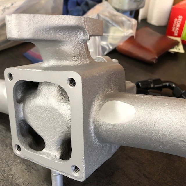
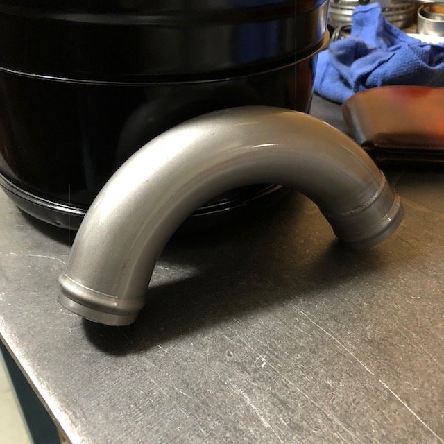
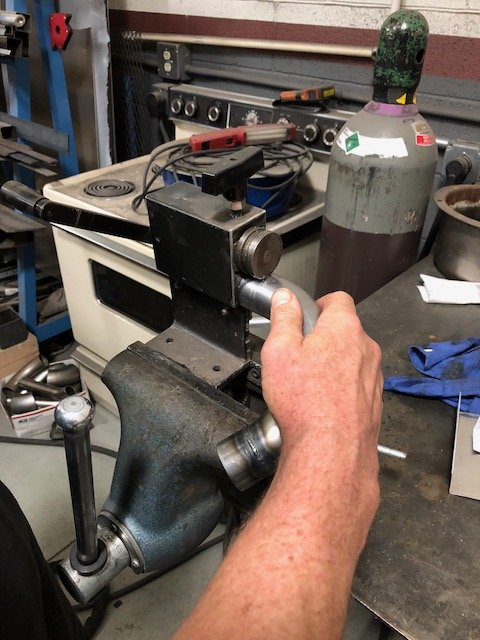
Have had better weeks automobile-wise.... Seems the timing chain in my Honda Accord maybe skipped a tooth while commuting for work and tweaked all the valves for its camshaft because in a very sudden moment I now have zero compression. So that needs to be addressed. With all my “projects” ongoing I farmed out the R&R job to a pal of Brian’s at AZ Auto Tech. I’d have to take a week off work to get it fixed, and I just can’t do it. Good news is that Brian can do the head for me for parts. With luck that’s all it is. Engine has run like an absolute champ for 11 years (366,360 miles) with naught but oil changes. But that’s another story for another forum ? Only a few things left ‘til “turn key” on the Plymouth. I wrestled with getting the intake and exhaust to mate up nice and sit flat together on the bench. Ran out of time Friday screwing around with it (after getting my Honda diagnosed and towed to the other shop). When I came in this morning Brian had figured out the ‘37 intake manifold and the later 23” exhaust manifold were making contact here and needed a little clearancing. Now they both meet the block tightly and squarely, and the exhaust riser surface meets square and tight too. He also spot faced the bolt holes on the exhaust manifold because they were far from square. Made a vacuum advance line that looks a little better than the one it came with. Runs around the back instead of over the top. I’ll see how I like it.... fan, pully and belt installed. Water neck installed. Hope the thermostat works okay.... it’s an old one.... Also, I didn’t realize I had a part missing for my lower hose when I ordered the hose kit. Found a picture of something similar on line and made one up. Brian was excited to have me use the bead roller..... Maybe it doesn’t get enough attention (shrug) but we employed it to roll some retention beads on the elbow. Know there’s no pressure in this system, but this step couldn’t hurt IMO... Also, the original style clamps ordered from bernbaum do not fit that lower hose. They just won’t tighten small enough.... I’ll have to find some different ones. Probably just go with standard fare hose clamps.... Next week: upper radiator hose, plugs and wires and fluids. Darn close to seeing what I screwed up when we turn the key for the first time.
-
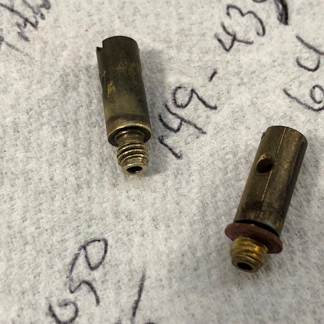
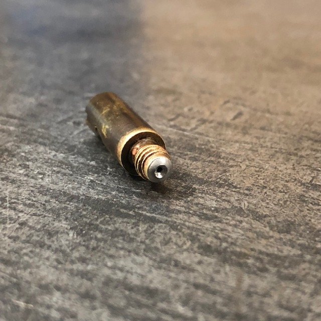
I completely forgot to do this, @Dodgeb4ya. Sincerest apologies.... But I remembered you’d asked when I came upon them while cleaning my shelf space debris in the engine room yesterday, and here they are.

-
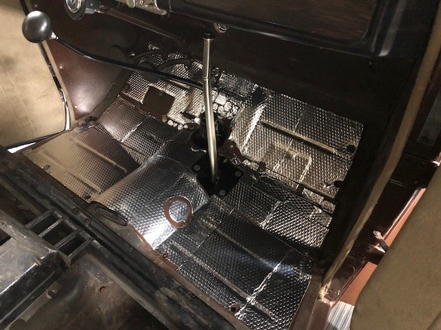
Yesterday was my wife’s and my 28th anniversary. Still, she let me go to the shop to make some headway. ? Got the floor in. Put an inexpensive layer of insulation down first. Hand brake installed. Floor mat down. Job is starting to look finished..... Radiator reinstalled. Not sure I like the flat black, but that’s how it came back. In it goes. And finally made up a new oil pressure line. Hard to see, but it’s in there.