
Merle Coggins
-
Posts
9,394 -
Joined
-
Last visited
-
Days Won
87
Everything posted by Merle Coggins
-
Have you checked with Napa, or other local parts stores for gasket kits for your engine? Also, once you find a good machine shop to do the machining work, they will likely have a good source for engine parts too.
-
Yeah, he's looking a little blue... ? Nice looking trucks.
-
It's an alternator that was originally used in many General Motors vehicles, Chevrolet, Oldsmobile, Pontiac, GMC, etc. It has become a popular hot rodder's alternator because they are relatively inexpensive and available almost anywhere.
-
White wire with black stripe connects to the wire that your took off the coil negative terminal. This is the wire from the ignition switch. Then the wire from the positive terminal that used to go the points now goes to ground.
-
Napa isn't a bad source for ign parts. Just call, or go back there, and verify that the parts you got are correct for your IAT-4011. If not, get the correct ones. If they are unable to cross reverence the distributor number then you may need to have the original Autolite numbers to cross reference. Some of the guys here have original parts books and can get those numbers for you.
-
 There are guys in here that talk about setting timing with a vacuum gauge. Essentially set your idle as low as possible, then adjust the timing to achieve the highest possible manifold vacuum. The RPM will probably come up a bit during this. Readjust the idle as needed, then take it out for a road test and listen for detonation/pre-ignition under load. Back it off, if needed, until the detonation goes away. I've never tried that, but they claim it works well.
 -
That would make sense. I missed the "distributor RPM" part. The specs are written this way so that It can be set up on a distributor machine. So you were correct. At anything below 700 RPM on the engine you should be at 0 advance. 700 is a fairly high idle speed for these engines.
-
not quite that much...
-
? You didn't notice the price may have been a little high for a 7.5mm bit?
-
11 degrees of mechanical advance + 11 degrees of vacuum advance = 22 degrees of advance. Sounds like everything is working properly. Set the RPM as low as you can when you set the timing. As your research shows, 0 degrees @ 350 RPM. This is where you'd want to set it. By 400 RPM you're already getting a little bit of advance. If you are setting it at 700 RPM your mechanical advance will be around 5ish degrees, so you'd have to set to that.
-
The trucks don’t use that type of connection, Greg. At least my truck tank doesn’t. It’s just a standard female inverted flare connection port.
-
Chinese Autolite spark plugs
Merle Coggins replied to PT81PlymouthPickup's topic in Mopar Flathead Truck Forum
Red Wing and Wolverine, both good American made work boots, although I'm currently wearing Sketchers steel toe boots. Not sure where they're made. -
1946 WD 20 Steering Adjustment
Merle Coggins replied to dodge 1946's topic in Mopar Flathead Truck Forum
... until it's full May sound like a smart @$$ answer, but that's it. Fill it until it's full -
wally’s 1948 B1FA-152 thread
Merle Coggins replied to wallytoo's topic in Mopar Flathead Truck Forum
I can almost hear that "Jimmy" winding up and running through the gears... A very unique sound. He must have it tuned up pretty rich if it was laying down that kind of smoke screen. -
53 Dodge pickup questions from a novice.
Merle Coggins replied to 53dodgegirl's topic in Mopar Flathead Truck Forum
Welcome. Nice find. What are the numbers stamped into the flat pad at the top of the block, above the generator? (Right behind the green hose in the pic above) This is the engine number and will help determine if this was a replacement engine, and where it may have come from if so. -
Strange Fuel Gauge Readings
Merle Coggins replied to 1949 Wraith's topic in Mopar Flathead Truck Forum
Hmm... I guess I skipped over the model year part too. Feel free to disregard my comments. -
Strange Fuel Gauge Readings
Merle Coggins replied to 1949 Wraith's topic in Mopar Flathead Truck Forum
I didn’t notice the thermal gauge comment from the OP. However, B-series trucks don’t use that type of gauge so maybe that’s why I over looked it. The image I posted comes right from the B-Series Shop manual. -
Strange Fuel Gauge Readings
Merle Coggins replied to 1949 Wraith's topic in Mopar Flathead Truck Forum
50mech, The truck fuel gauges are not thermal devices. They are magnetic devices. Here is an image from the service manual showing the dual coils. One constant coil that pulls to “E” and a variable coil, that connects to the sender, which will pull to “F”. As the resistance changes in the sender it alters the magnetic strength of the variable coil and the needle will balance between the two.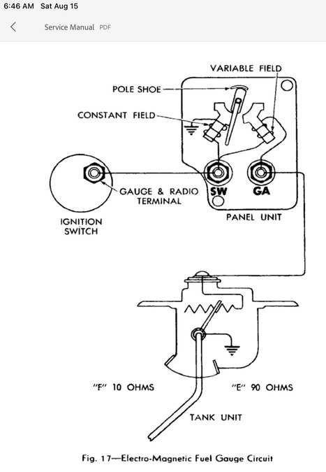
-
Strange Fuel Gauge Readings
Merle Coggins replied to 1949 Wraith's topic in Mopar Flathead Truck Forum
If your meter won’t read below 200 Ohms it’s time to upgrade to a new meter -
I don’t see why that wound’t work. An “ignition condenser” is just a capacitor in a fancy case for easy mounting
-
Strange Fuel Gauge Readings
Merle Coggins replied to 1949 Wraith's topic in Mopar Flathead Truck Forum
Sounds like a faulty sender to me. The fuel tank sender is a variable resistance device. When the tank if full, and the float is high, the resistance is very low which causes the magnets in the gauge to pull the needle towards the "F" mark. When the tank is empty, and the float is at the bottom, the resistance is higher which weakens the magnetic pull in the gauge and the needle moves towards the "E" mark. By your description the gauge seems to work at first, then starts going backwards. This tells me that as the float goes higher there comes a point where the resistance starts going up again instead of continuing to drop. You may need to pull the fuel tank sender and inspect it further. It can be tested out of the tank with an Ohm meter. -
1950 BIB Flywheel Removal
Merle Coggins replied to Alan Hensley's topic in Mopar Flathead Truck Forum
Never seen a 2”nut on a flywheel. Do you have Fluid Drive? There is a large nut on those to retain the clutch drive plate, but you don’t want to remove that if you don’t need to. And if it is a Fluid Drive there are 8 studs with nuts on the block side of the crank flange. You’ll need a 5/8” open end wrench to remove them, then the FD unit can be removed as an assembly. Be careful, it’s heavy. If you have a standard clutch/flywheel setup there would be 4 bolts holding the flywheel to the crank flange. Also, your thread title states 1950 B1B. A B1B wouldn’t have Fluid Drive, as that was introduced with the B2 series in 1950. Maybe your truck is a B2B? -
splt windshield installtion
Merle Coggins replied to ruff1148kr's topic in Mopar Flathead Truck Forum
I could hear the Benny Hill theme music in my head as I watched that. ? -
I'm not a fan of the pickle fork tools for separating tie rod ends from their respective homes. I've never had good success with them, and they tend to cause more damage in the end. I prefer a proper tie rod end puller tool.I have an OTC set, but my go-to from that set is this one. It has never failed me, unless space prohibits its use. That being said... I've seen a few guys that loosen tie rod ends simply by giving the steering arm eye a good rap with a hammer. Somehow that shock on the tapered socket will often pop them loose. I'm timid to try it and just revert back to my puller tool.
-
As I recall, this was a recent acquisition and was either an unrestored survivor, or an older restoration that hadn't been touched up yet. Memory is a bit foggy on those details as it was many years ago.