
JBNeal
-
Posts
7,192 -
Joined
-
Last visited
-
Days Won
81
Content Type
Links Directory
Profiles
Articles
Forums
Downloads
Store
Gallery
Blogs
Events
Everything posted by JBNeal
-
connecting rod remover
-

1953 B-4-B-116 BUILD THREAD Spring Special
JBNeal replied to JBNeal's topic in Mopar Flathead Truck Forum
not much spectacular goings on with the Spring Special these days, it's down on the priority list after this that & the other. I had cleaned the bed out when I got it, but it has slowly filled back up with some odds & ends. The doors were sticking when I picked it up a couple of years ago, but this past year, they have been a real bear, with the passenger door mechanism not releasing since last summer. A couple of months ago, I was able to pop it open on a particularly hot day, so I promptly began treatment with Marvel Mystery Oil on the door latches & hinges. Today I was able to open the doors easily for the first time...small victories -
that sounds like it'd make a good compact spare
-
nice pic...why not post some dimensions of the NOS bumpers and let Gary know what ya have and what he's selling. He may do something about it that could benefit his business & his customers
-
somebody call the Coast Guard, this thread has been hijacked
-
VINTAGEPIC: saw this B-1or2 on the Flickr:
-
Mr. Hopkins said I can finally buy his 48!!
JBNeal replied to Silo-rodncycle's topic in Mopar Flathead Truck Forum
here or here ? -
FYI I had put together a wiring diagram that includes some additional information that may improve headlight performance. One way to check the wiring posts on the AMP gauge is to hook the lead from the starter to one post, and the lead to the headlight switch to the other post, with lamps hooked up to the headlight switch. When the lights are turned on, the AMP gauge should read discharge. Or hook the lead from the starter to one post and a test lamp to the other post. Grounding that lamp should also read discharge. Once the AMP gauge is figgered out, then ya can move onto the ignition switch, attaching that jumper wire from the discharge post on the AMP gauge to one of the posts with the key in the 'off' position. A test lamp can be attached to either of the other two posts and grounded. The lamp should only come on with the key in the 'on' position. With the fuel gauge, attach that jumper wire from one of the key-on terminals. Ground the other terminal, and the gauge should read "F".
-
This reminds me of the first time I took the '48 for a state inspection. The inspector (a kid actually) made a disapproving face as he got in that old beast, then made an even more disapproving face when I had to stop him from twisting the key off in the ignition (the key is still twisted btw). When I pointed out the usage of that fourth pedal, he scoffed, and rather than let me start it for him, he stomped on the starter and it fired up...he then threw the stick all the way up and nearly backed into the car that had pulled up behind him. For subsequent inspections, I would start the truck for the inspector and remind him where 1st gear was
-
I have seen several variations on the poor man's security system on some vintage vehicles. There are battery disconnects that mount to the battery terminal and employ a knife switch to interrupt the circuit...I tried to install one once but had clearance issues with the battery cell caps & frame. I have seen quite a few master kill switches mounted under the hood near the starter...they were simple heavy duty rotary switches, some were heavy duty toggle switches, that could be reached after popping the hood. Then there are the ignition kill switches that can be hidden under the dash. A simple toggle switch interrupting the AMP gauge circuit could do the trick...maybe that's how Biff Tannen kept folks from taking a joyride in his Ford
-
if the brake system is sealed, then ya shouldn't have any need to top off the fluid. I've noticed on the '48 that the line from the master cylinder to the junction tee is always covered with dust. At least once a year, I've had to top off the MC, so I'm guessing I have a flare that's not seated perfectly and verrry slowly weeps out the DOT5. The '49 had so much leaking out of that same tube that I had to pump the pedal every time I used the truck...the flare on that one had a nick on it, but the brass fitting on the MC somehow got distorted somewhere along the way and the flare never really sealed right. That's one of them things I learned was that the factory flare and my flare were not the same size, so the brass fitting that comes from the factory might need replacing with a new one to get the flare to seal correctly. Of course there is so little room to get a wrench on that fitting, I had to pull the MC to get a clear shot at that fitting. With the MC in a bench vise, the old one came right out, and the new one was real easy to thread back in place
-
I was looking through my parts books, and it appears ya found one of the goofs in this manual. The horn button has the spring for the electrical contact, and the other spring keeps the contact plate against the lock ring plate that is held to the steering tube with the steering wheel nut. Occasionally these parts will pop up from time to time on eBay, ya might could get one from VPW but ya might want to verify that it's not for a Power Wagon as some of those horn buttons were different. One option is to take the horn ring, grind off what's left of the spokes, fill the exposed notches with an epoxy, shape/scuff the surface to get the plating blisters smoothed off, maybe use an etching primer, then paint the horn ring black, white, school bus yellow, or whatever
-
1948 B-1-B-108 BUILD THREAD Papa's Dodge
JBNeal replied to JBNeal's topic in Mopar Flathead Truck Forum
After many delays, I stopped by Crankshaft & Valve Service in Waco the other day to see about getting some inspection & machine work done to a flathead. They gave me their instructions & fee schedule for me to consider, as well as usual turnaround times for various services. My original plan was to take the donor Plymouth 218 to replace the Plymouth 218 in the '48. So I went to verify a few casting & stamped numbers, and got to scratching my head a bit. The donor 218 I found on a CL listing in Mason in 2010 was stamped P24 with a 5-22-50 casting on the block, no date casting on the head, and no internal bypass visible on either, but it has a remanufactured tag on it as well as the skinny belt crank pulley. The boss where the number is stamped doesn't feel particularly flat either, so maybe that P24 may have been put there well after the casting date which may explain the discrepancy. My guess is that this engine may have been a P19 or P20 before it was remanufactured, presumably in 1953. Then I looked at the Plymouth 218 in my '48, and the painted over stamped number was actually a P26 230, not a P25 218 as I thought it was. The block was cast 5-15-55; the head was cast 12-15-54. The block has a remanufactured tag behind the starter, so I'm assuming that the 230 was rebuilt with a head from a different engine as most original engines I have seen have casting dates within a few days of each other, not months apart. As hard as this engine is to turn over by hand, I'm aiming to do a complete teardown & inspection before I use it again (if ever). And then there is a stripped down P20 block with a casting date of 9-1-50 and a head casting of 9-5-50. This 218 block I found on a Brownsville CL listing 2 yrs ago is almost ready to go to the machine shop as it sits, with only the freeze plugs, the oil galley plugs, and other external block fittings needing to be removed. But the parts for this engine are in boxes, coffee cans, plastic bags, etc. as the previous owner tore this thing down then lost interest. So I'm not entirely sure how this goes back together or if I'm missing parts. So I looked at the other engine I have, sitting in the back of the '48, that I picked up near Houston via eBay 2 yrs ago. This P26 engine has head & block casting dates of 3-31-55 & 4-1-55, respectively. The engine turns with a little effort, as I can't remember the last time I fiddled with it. It definitely will need some machine work done, as there is a visible groove in #5 and a corresponding chunk missing from the piston. I've been stewing over which engine to choose for several days. My great-grandfather got this '48 in more than one accident; luckily he drove so slow they weren't too serious. But it is obvious that the front sheet metal originally belonged to a black B-2 Fluid Drive truck, not a green B-1. So this old beast has not been original since long before my lifetime, and I can only get it close to looking original at best. For now I am leaning towards trying the '55 230. I can do a complete teardown, get to know the innerds of this relic, and will probably have an easier time during assembly. If this engine has some serious faults found at the machine shop, I can fall back on one of the P20s. I have a T306 sitting installed in a parts truck, but I am not confident that engine can be saved judging by how open the engine was left by the previous owners. As I write this, I am hesitant to predict any progress as I have received an email and a couple of phone calls that may derail my progress yet again. Looking back at prior posts to see what all work I have listed so far is like a stroll down memory lane, as gaps in postings were filled with projects or emergencies that popped up, such as fixing several friends' cars (they turned out to be deadbeats, bless their hearts) & remodeling my parents' house & making unexpected repairs to my own house. So we'll what happens in a few weeks
-
them things are hard to come by unless ya wanna deal with ol' Big Frank:

-
I have seen several modifications available for 2nd Gen Ram steering gearbox stabilizers, so this might be one of them problems that Dodge lets the general public solve as needed, either from severe service or from wear&tear. These B-series frames aren't all that stiff as they are riveted together compared to welded frames, so there probably is flex in the frame while turning or while traveling over rough roads. I know of a few rub board roads near the house where I can have both hands, forearms & elbows on the wheel with tight steering joints and even at 35mph the truck wiggles to the left & right, presumably from some give from the tires & the frame. I haven't seen anything on other 1/2 to 1-ton trucks I've come across, but I reckon I found the steering box reinforcement that you are talking about in the parts manual for the larger trucks. On the 2nd Gen stabilizer, it is basically a bar that bridges the frame rails, with a plate that has a pilot bearing that rides over a special threaded extension rod that screws onto the steering gearbox output shaft. This restrains the cantilever forces on the gearbox to stabilize steering inputs & outputs. Something similar can be made with that big nut on the B-series gearboxes, possibly welding a tube & machined shaft to that nut as the output shaft extension. Some pics of the big truck solution might be nice
-
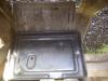
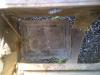
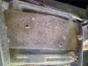
both trays are about 1 inch deep; the smaller mounted tray is about 7" x 9", or a tad larger than a Group 1 battery. The NOS tray is about 7" x 10-1/2", or a tad larger than a Group 2 battery.
-
I recall seeing in one of the Bunn books an early C-series cab & front sheet metal mounted onto a Power Wagon chassis and was listed as a "special order". It may have been possible that a regional dealer ordered a slew of 1-tons (possibly as a fleet arrangement with an owner-operator, maybe even a govt entity) and these trucks eventually found their way into the ownership of the general population. The local TXDoT office had a big auction back in '88, selling a bunch of their distinguishable construction yellow Chevies, and people came from far & wide to snatch these up as they were well maintained work trucks with ACs. Dad got a sgl wheel 1 ton, a few guys at church got the crew cab sgl wheel one tons for their personal businesses, several area farmers got the 4x4 duallies, and all used them for another 10 yrs before they all eventually changed hands again then faded from view. When I got the '49, I noticed the similarities between it's 1-ton rear axle & the Power Wagon rear axles and assumed they were almost identical. As a guy in NC was selling surplus Power Wagon parts on eBay, I snatched up axle seals for pennies compared with new versions available from NAPA. I eventually acquired a MOPAR parts manual that included B-series, Power Wagon & Route Van parts listings. Doing some cross checking, the only similarities between the B-series D rear axle & the Power Wagon rear axle were the inner & outer hub seals, axle shaft flange gaskets, and axle shaft flange studs. So I have some Power Wagon pinion seals that measure 4.000" OD, about 1.780" seal ID, outer bore depth 0.605", inner bore depth 1.005". These are stamped TROSTEL DF 240-156-12. They appear similar to what is listed on the T137 site.
-
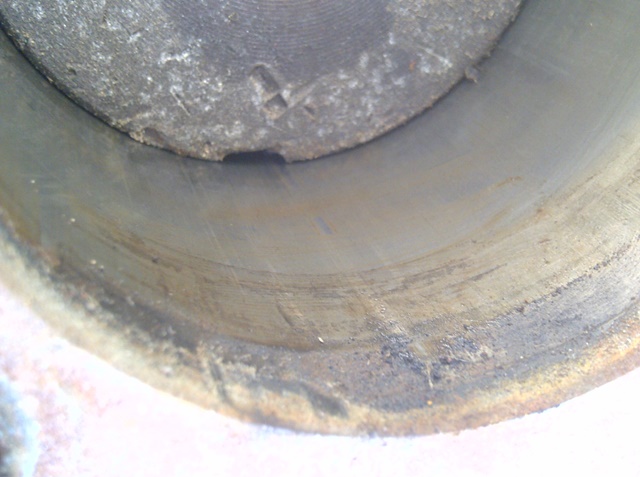
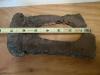
I have dismounted a set of B1D rims to chunk the old hard tires & tubes that shelled off their valve stems. I'm about to sand blast these rims in preparation for painting, but y'all got my attention with the comments about rust on the rings. So what is problematic rust on these lock ring wheels? If the rust is scaly within the groove, then it's time for replacement? So far, the only scaly rust I've seen is around the valve stem hole, and the ring grooves have surface rust.
-
going through my stash of parts, I found an NOS battery tray, but looking at the parts book, the part number written on the back of the tray is for the larger trucks. Comparing to the battery trays in the '48 & '49, it appears the subtle difference is in the dimensions of the tray as the big truck tray looks identical to the smaller truck tray. But the parts book does not really say that this tray is used on all B-series 1/2, 3/4 & 1-ton trucks. So I got curious and looked at the '51s next to the house, as well as the B4 Spring Special, and it appears there was a change somewhere along the way that the tray was eliminated in favor of just using the support found in the frame section of the parts book. Judging from the condition of the trays I have, they didn't last too long when exposed to the corrosive effects of leaky batteries & road debris. With the formed lip along the length of the support, and the presence of the hold down bolts, the tray seems to be a belt & suspender approach to containing the battery, and possibly a carryover from the car side of the business.
-
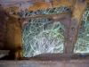
looking at the B1D116 and the B4B116 sitting in the yard, the original heavily weathered outside boards are close to 10". FWIW the B4 has 5 boards that are about 5-1/2", not sure when the lumber change was made from the original style...
-
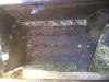
Years ago, I picked up the smallest Craftsman siphon unit that was on sale to clean up some wheels and smaller parts. I used it inside a pole barn with a dirt floor, so I employed an old pickup bed liner as a trough of sorts to work in. Even using care as to keep the sand aimed on the parts, I ended up getting sand on everything inside that barn (dust too) as the sand would bounce off the work parts and randomly track in every direction. Even wearing a hood, welding gloves, long sleeves & ear plugs, I still got dust in my eyes & nose, judging by the sinus headaches & whutnot that would follow the next day after use. And I was ignorant of the moisture filter that was needed, so my nozzle clogged often from condensation from the compressor. After going through several bags of sand doing sample parts & one wheel, I calculated my operating costs and compared that to the cost of a media blasting company that is in town, and I opted to have them blast my other wheels. Those wheels were scaly rusty, so those guys were gonna do a much better job than my li'l setup could do. But for other parts, the siphon unit did well, and with practice and patience, I cleaned up some sheet metal without damage. I also taught myself how to setup everything so once the blaster was running, I was cleaning one part after another with minimal stops and eventually learned how to estimate how much sand was needed to clean certain size parts. As I gear up to do some more sand blasting, I plan on making a temporary shed of sorts inside that pole barn so as not to lose so much sand, making a 2x4 frame with poly plastic sheeting to knock the sand back down to the bed liner for re-use. I definitely would not trust a media blasting company to do any sheet metal as them folks just knock rust off and don't care about warping.
-
unless ya had one of them mirrors on a telescoping stick, I don't think ya could get a pic of the fuel tank seal from underneath. If the seat could slide forward, then ya might be able to see something from inside the cab, but if it's stuck from not being moved for years, then skip it & move onto some of the more noticeable stuff I reckon. I figger the best shots of the fuel line (& vacuum line, if used) is from directly above, in front, and on the sides, kinda like on a drawing. Bend angles and radii can be estimated a li'l easier this way...thanks!
-
I'm just curious to verify what I might already know...
-
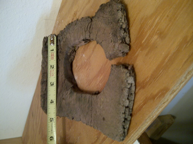
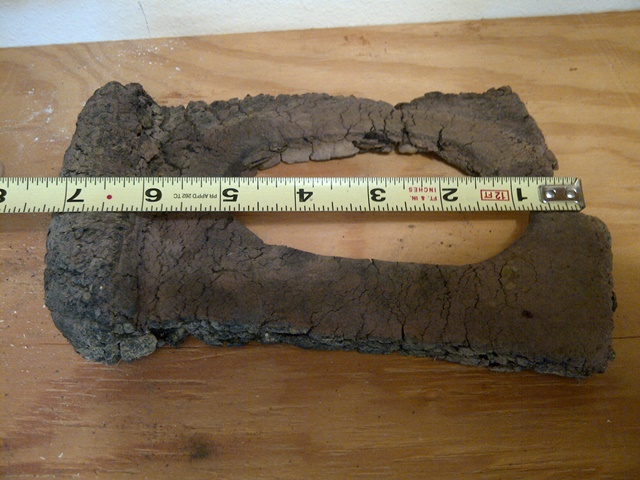
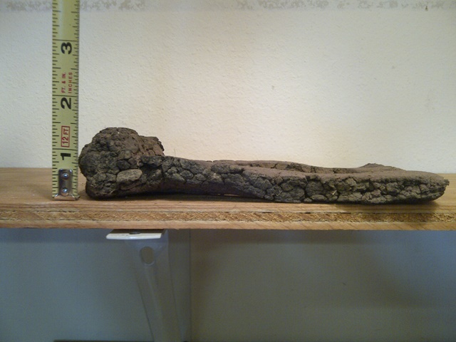
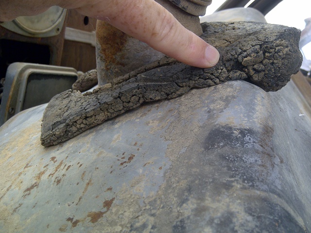
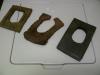
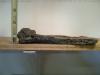
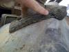
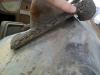
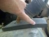
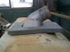
while cleaning & organizing in the garage, I had these fuel tank seals in the same place so I thought I'd display them. I have an old stiff mudflap that I cut to mimic the original (but it was too thin so it just rattled atop the tank), the original spongy rubber type that was on the '48, and a replacement that I made from a chunk of an old work station floormat. The original appears to be formed as shown in the parts manual drawing, and it has the indentations from being pressed onto the underside of the cab. When mounted on the non-B4 style fuel tank, the original gasket fits neatly around the tank neck and the adjacent formed area so as to fully contact the underside of the cab, completing the seal. Without that extra lump of material, a flat gasket will eventually droop in the area that would be under the fuel neck hose, forming an incomplete seal. I looked at the B4 Spring Special & it appears to have a flat piece of rubber about 1/8" thick on the inside of the cab at the fuel tank neck, but I don't know what is under the cab without removing the tank. As can be seen from the remnants of my original seal, the spongy rubber could split and the seal could slide off of the neck. I'm gonna guess that this happened on every truck that was driven on wet or dry roads, and the Dodge engineers decided to get away from this formed seal to a simpler (cheaper) rubber seal that just covered the gap. I think the only reason I have this seal is that my great-grandfather was a notoriously slow driver (think of the geezer who gets in the way in the bayou chase scene from Live & Let Die) and the original seal was never slung off of the chassis from going around a corner or flying over railroad tracks. The original seal material is still spongy, but the surface is crusty like melted plastic that has cooled off. It's not so much like foam rubber as it seems to be like foam asphalt, if there ever was such a thing. The material can be squeezed flat and feels like it gums together, but after a few minutes of sitting on a table, it expands back to its original shape. With the variations in what has been found out in the field by fellow forum members, I cracked open the parts book and tried to figger out which variation is correct. And it looks like there are several correct versions, as 14-86-60 has 3 listed part numbers in the parts book I have that was printed Jan.'53. There is a part number for the early B-1s; another part number for the late B-1s & early B-2s; and another part number for late B-2s, all B-3s & all B-4s. This may be another instance similar to the steering gearboxes, as the parts & shop manuals show a graphic indicative of early B-1 usage, but later B-series models have different parts used that look similar but are not the same as the graphic shown simply because Dodge did not update their literature. At any rate, only us pickers of nits will know the difference and can testify what is correct and what is homemade to this part that is rarely seen...as long as it keeps the rats from chewing the stuffing out of the seat, I reckon drivers can use whatever works best for them

-
I wouldn't mind seeing the door panels, seat, and if possible, what's left of the gasket between the gas tank & the cab from inside the cab & from under the truck. Also, a few shots of the fuel line from the carb to the fuel pump just fer grins...thanks!