


James_Douglas
-
Posts
1,927 -
Joined
-
Last visited
-
Days Won
23
Everything posted by James_Douglas
-
I have been running these on my two 251 flatheads for years now. ARP HEAD STUDS: Studs: AP3.500-1LB (7/16 x 3.5 stud w/broach) Washer: AAPW1316N (Washer 1/16ID 13/16OD non-Cham) I think I used chamfer ones on the '49 it really does not matter much as the head is dealing with the thread pull back issues. Nut: APN1116 (7/16-20 Hex Main Nut) If I was doing it again, I may try and get a few head studs a 1/4 inch longer of thread at the top (if the shaft does not stick up to the flat on the head and allow it to be torque correctly) so that if you wanted or needed to put any kind of mounting plate under the nuts you would have plenty of room to do so. James
-

Three Speed with Overdrive Reference Photos
James_Douglas replied to James_Douglas's topic in P15-D24 Forum
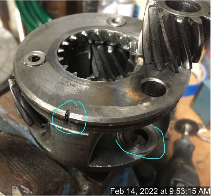
What is interesting is that on the gear where the needle bearing failed, the washers that act as the thrust bearing and hold them in were no place to be found. They were ground up completely, along with 2/3rds of the needles, which is very odd. There is a fair amount of material in the ring gear bottom grooves and as the planet assembly rotated it pounded that material in fairly good. No doubt that is what was making the noise. It appears that the gear itself with all the needles gone backed away from everything and just went for the ride. It does not look like ones I have see online where the gears are stripped out. Interesting.... James -
Three Speed with Overdrive Reference Photos
James_Douglas replied to James_Douglas's topic in P15-D24 Forum
Ok, I am sitting on my hands as the proper pinion bearing is back ordered. Someone higher up at SKF was very nice and found two and released then to distribution so I could order them. Now the bad weather in Nashville is slowing down UPS so my 2 day air is not going to get here today. While I wait on that and the grease, I took apart the bad planet assembly. I used a dremell cutt off wheel and slit through the tin steel cover and slightly into the forging. I then was able to pry back enough to get it to come off. I do not think the slits will cause stress raisers and in any event when I put it back on I will mig weld three tacks and that should get it back on and prevent and cracks. The thing you cannot see in the photo is the blind pin that hold the center race in is in two parts. When you drive or press the center out the pin shears off clean and easy. The part in the body is easy to pop out but the part in the center race shaft is blind. Too some work to come up with a way to get it out. So now I need to look into making new center shafts as the one that failed as well as the other are showing since of the needle bearing going through the case hardening. Then I also would need to find a set of needle or other bearings and the thrust washers. The tough part will be finding out how much for a gear company to make new planet gears... It is something that can be done and if it is one would have a new planet assembly. But the time and money will not be trivial. James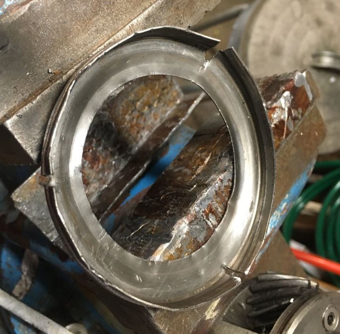

-
After my painful experience with the 1949 Desoto engine, I plan on pressure testing any flathead I am going to rebuild. I plan on pressure testing BOTH the water jackets and the oil gallery. The 1949 Desoto engine was pumping oil into water jacket. It took a year to figure out what was going on as it was a slow leak. The oil ended up in the top of the cylinder head, as oil floats on top of water, and then then the oil caused the heat to overheat and crack. If you look at a cross section of the blocks there is only about 1/4 inch or so between the oil gallery and the floor of the cooling jacket between the cylinders. Age and rust down there can lead to porosity issues and the 40 PSI oil pressure can push through it. I had an old drag racer I know suggest that I may want to use a very thin, like 1/4 inch, layer of the stuff that is used in drag race engines to stiffen the blocks. It is some kind of pour-able two part epoxy that the pour down into the jacket. His thought was that it would seal and porosity that may be down there. But the block would have to be cleaned and then acid dipped to get the rust out for that to work. Probably easier to test 3 or 4 blocks until one passes a 75 PSI oil test and a 20 PSI water test. James
-
I wish I could fine some documentation as to why Borg Warner did not want to use hypoid. I suspect like Loren stated that the sprang clutch is the issue. On the trans side the issue is the yellow metal of the syncromesh and that is why one should never use an oil or ATF with "Active Sulfur" as part of the additives. Many of the zinc additives today also have sulfur in them so make sure that inactive sulfur is what is in it. I did find an very short article on the subject of sprang clutches from a manufacturer who states that additives can prevent the sprang from properly working as one engineering element in designing a sprang clutch is the coefficient of friction. This also makes sense on the BW overdrives in addition to the fact that the Balk ring works by friction and BW makes a big deal in the book on checking the pull force with a spring scale to make sure it is within the specifications. Again, a friction coefficient part. I guess if a lubricant sticks too good to these parts it upsets the calculated friction and the parts may not work as intended. I did net a reply from Lubriplate and they said they have an assembly grease with a very low melting point. I may try that. Sniper, thanks, I have several wood dowels that I made 15 years ago and use them to put the needle bearings in. I do find that some lube helps to keep them in even with the dowel. The rollers for the sprang on the OD have to be greased to get in and BW tells you to do that. BUT, the old drum only grease had a much lower melt point that the new grease I am told. James
-
I have one. I don't know if it is here or at my place out of town. If it is here I will get a photos today for you. James (1947 Desoto)
-
When I pulled part my transmission and examined the parts, I noted that the rear of the counter shaft was worn through the case hardening. These are all NOS parts when I rebuilt it 15 years ago (50K miles). I do not mean some wear, I mean a lot. When I examined the shifter housing I also noted that at the "oil level line" and above the wheel bearing grease I used in assembly had not completely washed away from the splashing oil. I have emailed several of the companies that market assembly grease that is labeled for transmissions. Including manual transmissions. What I got back from to of them so far has been interesting to say the least. When I wrote then I explained about how these older transmissions had cast iron housings and much heavier internal steel parts. I also explained that why mated with the Borg Warner Overdrive that made them even larger and that the BW overdrive had an iron clad requirement for no Hypoid additives no matter what. So far the responses have been that although they list their product for manual transmissions, that they felt the the older transmissions would not get hot enough to cause their product to melt away and could starve the needle bearings and cause accelerated wear. It may take months for it to wash completely away from the bearings. I am waiting on the other companies responses. There was an article on Engine Builders website that talked about the positives and negatives of assembly lubricants and how one has to be careful to match the grease to the need, lest one can create an issue. Enlightening. Now that I have one transmission ready to put back together and another in the pipeline, I am trying to figure out what to use to hold the bearing into place. James
-
Need some some help on brake line routing for 48 DeSoto
James_Douglas replied to MarcDeSoto's topic in P15-D24 Forum
One thing I will do the next time the dog house is off the front end is to make a modification on the brake light switch. It is a bitch to get at after the car is back together. On long road trips if the switch dies and you need to change it in a hurry, and I always carry a spare, it is not fun. I will add a pipe that comes up onto the drivers side inner fender someplace easy to get to. Then stick the switch on the end of the pipe. Re-route the wires. In this way you can change the thing quick and easy. Since it is a hydraulic system it does not matter. I even thought about using a tee on the end and screwing two switches on the end. One live and one spare. Then if one died, just swap the wires and worry about replacing the dead one at one convenience. James -
What is the area calculation? Meaning what is the area of the valve stem versus the stem and the guild. Removing the top of the guide, how much area is picked up? Or....fill a port with a valve and guide and then do another with a cut guide...with silicon fluid which flows and hardens and then pull it out and measure it... Then calculate the % difference and see if it looks like it is worth it. It may be that port matching, bronze guides with tighter clearnaces and a little head porting may yield more than cutting guides... James
-
Need some some help on brake line routing for 48 DeSoto
James_Douglas replied to MarcDeSoto's topic in P15-D24 Forum
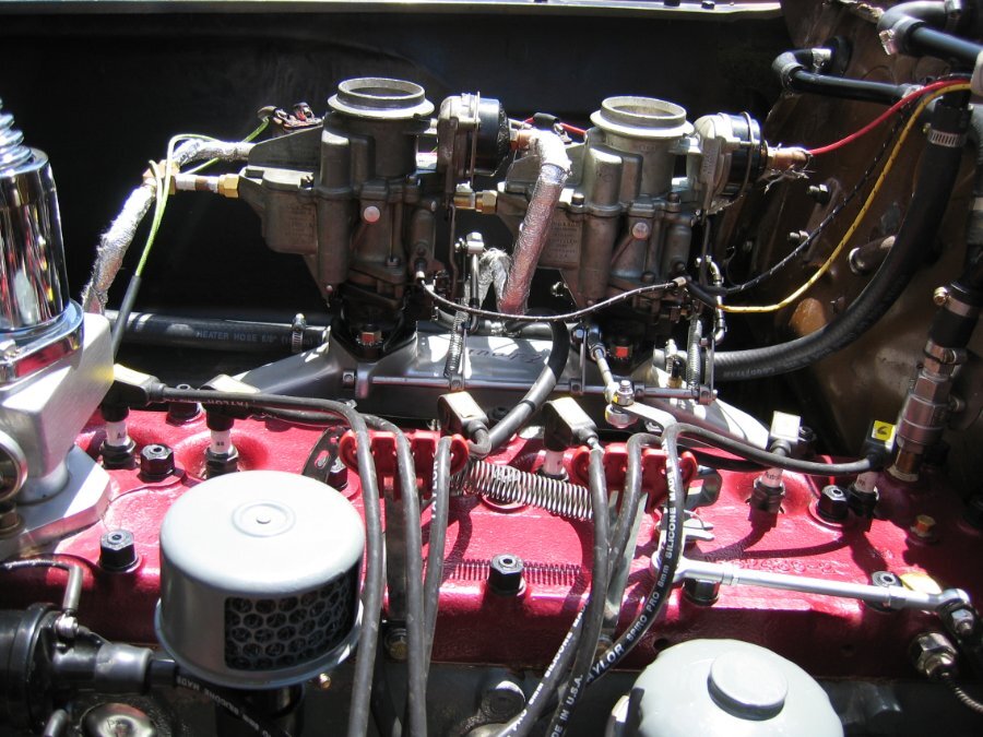
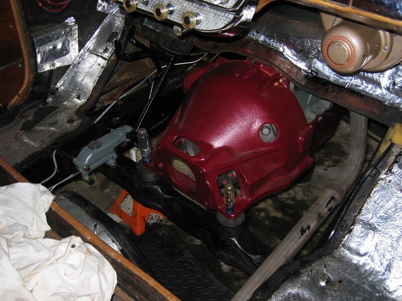
These photos should give you an idea of what my 1947 Desoto looks like...


-
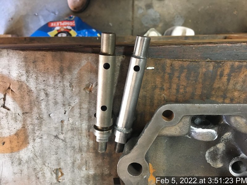
The two hole version can be used with either collar. The one hole version has to have a specific collar (lower recesses for spring). I am covered for both transmissions. James
-
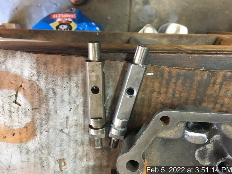
Ok, After a couple of hours I figured it out. The did in fact make a change, although it is not documented. They went from the spring being on the bottom and having to access it from the back side which is a PITA, to having it on the top on the front side. One way it push on the bottom and the other way it pushes from the top. It works just the same, same motion and same tension. The later one has two holes as the part the goes around it and moves is in fact different. In one it has a recess for the spring on the bottom and on the other it has the recess on the opposite side at the top. I guess they made the later shafts so that they could be used with both of the other parts. Why they made the change is left to history as there is no functional difference. James
-
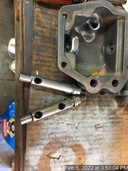
I have TWO of these transmissions and each one has a different part in it. One has the spring in the top and the other on the bottom. I checked the parts books and I see the drawings show BOTH of them without any explanation. I have checked several service manuals and NONE show the detail of where the spring goes. One of these used the top hole and the other used the bottom hole. So, which one is correct? Chrysler is well known for making a running change in a part and using the same part number. Drives me nuts! I guess this will tale some work to run down. One thing is I saw someone selling this part in sets of three. They list the part number and two are of the one style and one is of the other...same part number... When I went to reference my other one, it had the spring in the top hole. When I took apart the one I have used it was in the bottom hole. I guess I will have to dig a little more unless someone here can shed any light on this. If someone has a trans apart, I would not mind a photo of the cover showing where the spring is...high or low...and the trans ID that is stamped into the flange on the side of the case. James
-
Ok, So I grabbed my spare three speed lever cover to make sure I was putting the shafts in correctly...the one that slides into the other and has the spring in it. To my shock they are different. Both three speeds. The cover case part numbers are the same as are all of the internal parts. Just the shaft is different and where the spring goes is different. Has anyone see this before? James.
-
The last head I did required that we place the head in a mill and equalize all the bolt bosses as they were not all the same. So, be careful measuring a head thickness. I sandblast the heads then I CC them. I then place it on a block (with an old gasket) with a crank and cam and rotate it. I place modeling clay across the valves and see how much clearance is left after I run the thing around. That is the only way to know for sure that you will not have a valve hit the head as these heads have been cut too many times. Once I am convinced that there IS room to use the head I then take it in and have it cut. I then CC it again and also do the valve clay thing again just to make sure. With the head CC, the gasket numbers, I can then come up with the exact compression ratio I want. In the event I need more room, like if the block was decked too many times, I would order a solid copper head gasket in the needed thickness. If you look at older posts between myself and Don you will see we came up with a general rule as to how much you can taker off and what that does to the compression ratio all other things being equal. Of course our work was on the 25 inch blocks, so I would take it with a grain of salt on the 23 inch engines. CCing is the only route to knowing what you are getting no matter the engine or head. James
-
I am not sure I understand the question. One overbores the tappet bore holes and then presses in the silicone bronze sleeves then hones or reams them to the stock hole size. You then slip in the tappets in the normal manner. I think you are talking about bronze valve guides. I am talking about tappet bores. For valve guides, I am going to have bronze one machined in place of the cast iron ones. I am looking into some kind of seal on the intake guides as well. James
-
I will be doing a new engine later in the year. I plan on having all the tappet bores sleeved with one of the many bronze blends available for such use. One can then use a tighter clearance due to the silicon in the bronze. I can then use also new standard size tappets. James
-
One other idea...take a look at this... https://www.web.imperialclub.info/Repair/Lit/Master/018/Page16.htm When I got my trans from one of the usual suspects, this interlock plunger was nearly stuck in place. There is a cup seal that you have to get out to get this little plunger out. Even then as it is a blind hole it is not easy if it is stuck or mucked up. This thing is critical to the smooth shifting. It needs to be very clean in that bore and the plunger needs to be nick free. The only way I could get it out was buy using a 90 degree screwdriver and forcing it back and forth with penetrating fluid until I got enough crap out so that if I tapped the housing on the bench five or six times it would come out. I then scrubbed the bore with a new wire brush. This is on of those little detail items that make a very good rebuilt from a half-baked one. It also can apparently cause the trans to lock it it is missing or not moving properly. James
-
Heater valve replacement (generic Amazon sourced)
James_Douglas replied to Loren's topic in P15-D24 Forum
Loren, I like the union idea. The next time I have my head off, I will add that to my set up. Do you have photos or part numbers for those so I can try to match it up via McMaster or Amazon ? James -
Does anyone sell 7.60 x 15" black wall tires for my 48 DeSoto?
James_Douglas replied to MarcDeSoto's topic in P15-D24 Forum
Diamondback will make a black smooth wall for you. Call them. James -
For when your wife is better and you get back to your hobby... One thing I cannot tell from the photo...are you using the stamped steel clutch gear plates or the solid steel ones? For some reason MOPAR switched to the solid steel plates and in the books told the service folks to swap out the stamped steel ones if they had it apart. I put in new solid steel ones on my transmissions. James
-
Heater valve replacement (generic Amazon sourced)
James_Douglas replied to Loren's topic in P15-D24 Forum
Turn out that the stock arm fits on this valve stem. Even the flat spot. I made up the plate and then took off the cable holder from the factory unit and welded it onto the plate. Stock cable. and it all works fine. James -
Three Speed with Overdrive Reference Photos
James_Douglas replied to James_Douglas's topic in P15-D24 Forum
I just spent the last couple of hours going through three used and one NORS main shaft and several sets of second gears and clutch gears all NOS or NORS. I found that the NORS main shaft was worse as to end play than the two used main shafts. I also found a difference of about .002 in thickness of the NOS second gears. By playing mix and match I was able to come up with a set that is at about .005 or .006 inch. Now this is with parts not perfectly clean, I cleaned off the cosmoline with a razor blade but not perfectly clean. So add about .001 for that. At .007 it is within specification by .001, but the good book says that anything close to .008 should be replaced or it will get noisy in time. All that said I went back and measured the shaft, clutch gear and second gear with the bad tooth and it is about .012 after 60K miles. It was not making noise. I am going to build this trans with this set up to get it back on the road. In the next couple of weeks I am going to take two more second gears down to have them industrial hard chromed to add enough so that I can use the NORS main shaft in the spare trans and have one extra second gear as well. I am hoping the by chroming two or three I can get the unit cost down, but it is likely to be $100 to $200 per a gear. James -
Three Speed with Overdrive Reference Photos
James_Douglas replied to James_Douglas's topic in P15-D24 Forum
One of the big problems I am running into is that even with NOS and NORS parts that getting the second gear to be well under .008 is not going to be easy, quick or inexpensive. I have tried one NOS, one NORS and three used Second Gears. I have tried these with two used main shafts and one NORS main shaft. None of them are under .008. The NOS second gear that was in the transmission, not making any noise that I plated 15 years (60K miles) ago and is .004 clearance has a gear tooth that was cleanly severed at the root! I have no idea how or why that happened. The transmission also had a part of the reverse idle gear that had a tooth cracked off. It is possible that the reverse gear part got into the second gear and caused the problem. I have thought about turning on a lathe the clutch gear stop back on the main shaft .005 to bring the second gear to about .003 to .004. I would have to use a thicker snap ring to push the clutch gear back. BUT, this would push the syncromesh to the rear the same amount and the relative angles of the syncromesh teeth are critical to proper and quiet operation. I worry that moving it back will cause and issue with the input pinion syncromesh teeth. As to Snipers comment...yes shims are used in modern transmissions. But the design of them was built from the ground up to use them with plenty of thrust surface on both sides of the shims. The design of our MOPAR three speeds is not one of them. The "flutes" on the back of the second gear may well chew up any shim. Also, we are looking at something on the order of .004 to .005 shims, not .010 or .020 in thickness like may modern transmissions. I think using something so thin that does not have a wall height of at least 3/4 inch and corresponding thrust wall height is playing with fire. The flutes one the one end and the brass syncromesh gears on the other make it not possible to have a shim with any appreciable wall height. The only thing I can think of that keeps all the syncromesh geometries as the factory intended is to either move the flutes forward about .005 which is not really something that can be done easy or make the rear side of the second gear thicker to make up the distance. I may have to put a set together to get the car running and just know that second gear my make noise, or it will in the near future, as it is not within the 0.008 or less specification. The MOPAR service booklets make it clear that anything approaching .008 will start to make noise. I then can take my time to get the other transmission built up when I get the second gear rear face chrome plated. In fact, I am going to buy a couple more second gears and have several done so I never have to deal with this particular issues again. James -
Heater valve replacement (generic Amazon sourced)
James_Douglas replied to Loren's topic in P15-D24 Forum
One can take a look at this old thread to see what I did. Some 15 years ago. No leaks, works fine, 100% water cut off. The only thing I changed in the 15 was to add a positive stop so I cannot pull the cable too far and go over center on the ball valve. Stainless, never rusts... James
