


James_Douglas
-
Posts
1,923 -
Joined
-
Last visited
-
Days Won
23
Content Type
Links Directory
Profiles
Articles
Forums
Downloads
Store
Gallery
Blogs
Events
Everything posted by James_Douglas
-
 I am posting this a new thread so folks and find it easy. When installing the extension housing on an OD transmission the books say to have the slot in the shift rail facing to the top of the unit. This can drive you nuts. You do it literally and put the housing on and it does not work. You can go through the entire process and put it into the car and not find out until then it is wrong. Lucky my little voice said something was wrong and I went over it a second, third and fourth time. There are several different ways that the control shaft and lever can go in. Some of them appear to work when in fact they do not. Some just will not work at all and one other way is correct. The problem is the service books tell you, "Turn the shift rail so that the slot is in a direct vertical position." Now I took that to mean the opening is to point up. No. What they mean is the back wall of the machined slit in the round rod is to be perpendicular to the ground. The machined back wall of the slit should not be parallel to the ground. One can conceive of the slot to mean the open end and that should face up, but this would be wrong as I found out. After a couple of days trying every combination of the shift rail, the manual control shaft and the lever...this is a place where one can easily get screwed up. FYI. James
 -
Marc, as to the anchors... Take your tool and place it at the base of a shoe near the anchor. Then rotate the anchor cam bolt until the shoe moves away from the tool. Then reset the tool and do it again and again. You "hunt" to find an anchor location that has the shoe as far in as it can go on the anchor adjustment. You do this with the minor adjuster, the one in the backing plate with the spring behind the big 3/4 inch adjusting nut all the way down. You can do this without the pin at the top. Mark with a heavy sharpie a line to show the lowest spot on the bolt. Both in the backing plate and even on the rear of the bolt. On mine, I mark the threaded rear side of the bolt and I use two hack saw blades and I cut a groove on the end. I can then adjust the anchors from the rear with the drum on. Yes, you have to leave the nut somewhat loose. But once one is happy with the fitting you back off the minor adjusters and slip the drum off and then tighten the anchor bolt to spec. You then can put the drum back on. The quality of the braking is vastly improved on these drum systems if you get the shoe to be a perfect match for the drum, minus the 0.030 underside of the shoe. If one just puts them in and cuts then to do it then the ends will wear out long before the middle of the shoe as well as the fact that it take several thousand miles for a shoe to "arc itself in". It may feel better after a few hundred miles, I geometry is geometry and the shoes will make maximum contact if not arced. The choice is do it correctly or plan on wasting 1/3 to 1/2 the shoe life. James
-
The factory spec of 3/16 of an inch is for NEW drums at exactly 11.000 inches. The shoes should be cut to a drum diameter minus 0.030 of an inch. Which is why I asked Marc do DOCUMENT the drum diameter in at lease two planes to make sure some idiot did not mis jig the drums and turned them off center which would cause problems with the shoes. Also the comments about the pins should not be taken lightly. A few thousands will not allow the shoes to seat down and allow the drum to fit down. Just ignoring that there is a problem by cutting and cutting the shoe is kicking the can down the read and will come back to bite one in the butt. Marc should figure out why he is having a problem. James
-
Go to the Chrysler Imperial Club site and rear the service repair documentation. https://www.web.imperialclub.info/Repair/Lit/Master/index.htm
-
Marc, You really need to stop and spend a couple of hours both reading and watching the Service booklets and slides. They go into much detail. I suspect you are not following step by step the process or the process has not "clicked" in your head so that you are not "seeing it" in 3D in your head. You need to KNOW not think that the anchors are adjusted all the way in and that the other adjusters are also all the way down. What was the measurements on each of the drums that they made? Did they take the measurements 180 degrees apart to make sure that the drums were in fact round and not off set turned by some shop that did not know what it is doing? James
-
Look up old threads by Don Smith on the conversion of his '48 Desoto. Although the Desoto Suburban has a larger steering box, I think the output splines may be the same. He found that a particular power steering box was splined the same.
-
Does not the service manual for 1946 have that in it?
-
The anchor bolts are cam shaped. But on your miller tool, set at the drum size and turn the anchor bolts pull the shoe as far away from the tool as you can. I am assuming the the the adjusters mid backing plate are turned all the way in. James
-
My 1960 Wagner Brake catalog shows the linings for desoto 1946 to 1954 with a 6 cylinder as 3/16 of an inch. Now, keep in mind that the Wagner cat also lists part numbers to order the shoes with the correct oversize for a turned drum. Those would be larger than the 3/16" for a standard none turned drum. The MOPAR books when they show the thickness is for a shoe BEFORE GRINDING. If you used a 3/16" lining there would be nothing to grind if the drum was oversize and it would not stop well as the arc of the lining would not match the arc of the drum. That is why in the MOPAR parts books it is thicker than 3/16.... To do it correctly for maximum braking the arc of the shoe needs to match that of the drum minus I think it says .008 inch. Slightly tapper the very ends so it does not grab. They did not list the length of the push rods. James
-
Wow, thanks for the warning. James
-
Hi all, I am posting this question here so as not to start another thread... Does anyone have an R10 sitting on the bench right now that they have not taken apart other than pulling the R-10 out of the transmission case? I need to know how much movement you get on the overdrive control shaft when you move the overdrive lever on the side of the case. I am just getting a very little movement of that shaft when I move the arm after putting it back together. I cannot for the life of me remember how much or how little it moves. So, if someone has one that they have not torn down too much, I would appreciate it if you would move the lever and tell me how much movement you get. Thanks, James
-
A new kind of eBay Hell --- whatch out on old car parts
James_Douglas replied to James_Douglas's topic in Off Topic (OT)
Think you are probably correct. I suspect that they put it into the wrong box and often people just toss the items in their box into a bag and don't look at it until they get home. Then they often just toss it out and don't bother to take it back to the post office. I have gotten things for other boxes over the years. So I know it happens. We will see. James -
People are going to love this one. So on Jan 5th I ordered a small parts kit for my 3-speed transmission from one of the usual eBay sellers. The seller said they were away until early February which did not bother me as I knew I would not need the parts until the last couple of weeks. A couple of weeks ago I never got the eBay email that it was shipped so I write the seller. He replied that they shipped it out and that I received it on January the 12th. He has a USPS tracking number that says so. I never got the package. It went to my Post Office Box. I suspect that the seller either fat fingered the Box Number and it was delivered to the wrong box or that the Post Office put it into the wrong box. The seller will not refund the sale. So, I have to wait until the 26th to ask ebay to step in. Lucky this was not an NOS, NORs or rare old used part that cannot be easily replaced. The lesson here is that if you are buying something on ebay that costs a fair amount of money, then one should demand a signature. I may be out $150 plus my time and aggravation. I am also going to lock out this seller and never buy anything form them again. A word of warning. James
-
Marc, Something does not sound right. Can you post a set of detailed photos of: 1. One of the shoes. 2. The wheel cylinders. 3. The anchor bolts. 4. The adjuster cam. You really cannot had sand the shoes and get them correct. You will just make a mess. Call around and see if anyone has and will arc the shoes for you. If not, then try calling Moose Motors Obsolete Brake Parts at 707-792-9985. Jeff, if he is still in business, can sell you a set that he will arc for the drum size you give him. James
-
Odd, I wrote to the company that makes Lubeguard and asked about its use in cast iron three speeds of 1940's and 1950's vintage with yellow metal and overdrive with sprang clutches. They wrote back that their grease may not melt due to lower temperatures of the the older manual transmissions due to their mass. James
-
One thing to note for anyone who has or finds or has someone to arc shoes... There was a running change in the Ammco brake shoe machines. Some of them had the clearance built into the machine so if the drum was say 11.040 you just set the machine to 11.040 and arced the shoes. Some of the machines you had to do the math to set the dial caliper as the clearance was not built in so you would need to set it to 11.040 PLUS the clearance. I have received shoes that did not fit because someone was using a machine and not following the proper setting procedure. ********************************* ADDENDA TO INSTRUCTIONS FOR MODELS 850 AND 8000 BRAKE SHOE GRINDERS. 1. The recommended .030” cam grind mentioned in point 3 on page 3A has now been built into the micrometer setting of your brake shoe grinder. Therefore, dis-regard the example “A” on page 3A. 2. Set the micrometer dial (3-Figure 2) to the diameter of the drum in which the shoes are to be used. Doing this will automatically give you the correct cam grind. ******************************** In the event anyone needs it I have attached the manual for my Safe Arc machine. Also, not in the manual that for the Chrysler Type arcing you need to use the fixed anchor head. 90% of the shops either do not have that head or do not know were it is. They they default to the Bendix head and the show geometry does not come out correctly. Lucky for me I have both heads. James Model_8000_Safe_Arc.pdf
-
Transmission case plug modern x-ref ?
James_Douglas replied to James_Douglas's topic in P15-D24 Forum
No it is a hammer in plug. Very small. -
Hello, Anyone have a cross reference for the very little 3-speed case plug for the interlock plunger? MOPAR Part Number is: 865892 I am trying to save time by not having to measure it and hit the books to match it by size. Thanks, James
-
BW said in their manual to use SAE 40 or for high heat - heavy duty use run SAE 50. James
-
I got a couple of tubes of the Lubriplate assembly grease and it is fairly thin. Much thinner than bearing grease. I will try that and see what I get. It is nice stuff for the general assemble in any case. I got a response from the Engineering Manager of one of the largest OEM makers of sprang assemblies for the auto companies. He confirmed that when the large rollers in the overdrive freewheel cam climb the ramp that EP additives create a boundary layer that tries resists metal to metal contact. In fact the harder the push the more the EP chemicals resist. This will case slippage in the cam and can damage it. You want it to have the roller and the cam have metal to metal contact and lock. So, with respect to Borg Warner overdrives one should never use any lubricant that has any of the EP (hypoid) additives in it no matter what. That takes some detective work to make sure there is none in there. Guess SAE Motor oil it is... James
-
When looking for something else I ran across my noted from 2010...note this is for a Desoto 25 inch block and an NOS head I used: Max out of flat for the block or head on a flathead six is: Length < 0.006 and width 0.002 Finish on block and head should be an RN between 30-60. Felpro gaskets (7256) for these heads contribute to about 18.5 CC on each cylinder. You get a loss of about Seven (7) CC's for every 0.024 taken off the head. Using some milling charts that are floating around I get about one (1) CC loss for every 0.0034 taken off the head. A stock head is about 110 CC's and is 1.930 thick. So if you want to end up with a 7.7 compression ratio, you need about 84 CC's assuming a gasket thickness of 19 CC's and a deck of ZERO on the block. I milled mine another 19CC's to get it down to about 84 CC's. I went through the trouble of polishing all the undersides of the combustion chambers and equalizing then to within 1 CC. Helps with the idle to try and get the final compression ratio as even as possible. But that is nit picking... Given that some of the chamber designs are a little different, this needs to be taken with a gran of salt. Take off a little and CC the head, then take some more and CC the head. Because of the basic shape 0.0034 first cut will take off less than later 0.0034 cuts. So don't try to cut too much off in one pass. Yest the machine shop will not like it and they will charge you a set up fee each time, but do it in steps so you do not screw up the head. Also, make darn sure they mill the the top of the head boss's where the bolts/nuts go to make them the same before they mill the head. Those boss's are not always on the same plane and the head can be milled into a wedge shape if they are not. I have seen this. I am not sure why some of them are off, but they can be. James
-
I have been running these on my two 251 flatheads for years now. ARP HEAD STUDS: Studs: AP3.500-1LB (7/16 x 3.5 stud w/broach) Washer: AAPW1316N (Washer 1/16ID 13/16OD non-Cham) I think I used chamfer ones on the '49 it really does not matter much as the head is dealing with the thread pull back issues. Nut: APN1116 (7/16-20 Hex Main Nut) If I was doing it again, I may try and get a few head studs a 1/4 inch longer of thread at the top (if the shaft does not stick up to the flat on the head and allow it to be torque correctly) so that if you wanted or needed to put any kind of mounting plate under the nuts you would have plenty of room to do so. James
-
Three Speed with Overdrive Reference Photos
James_Douglas replied to James_Douglas's topic in P15-D24 Forum
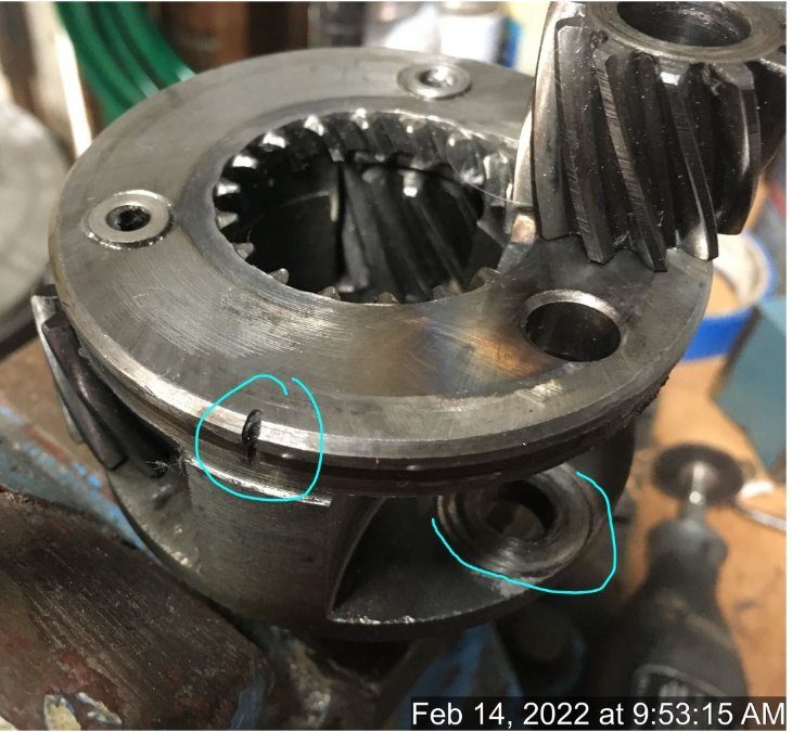
What is interesting is that on the gear where the needle bearing failed, the washers that act as the thrust bearing and hold them in were no place to be found. They were ground up completely, along with 2/3rds of the needles, which is very odd. There is a fair amount of material in the ring gear bottom grooves and as the planet assembly rotated it pounded that material in fairly good. No doubt that is what was making the noise. It appears that the gear itself with all the needles gone backed away from everything and just went for the ride. It does not look like ones I have see online where the gears are stripped out. Interesting.... James -
Three Speed with Overdrive Reference Photos
James_Douglas replied to James_Douglas's topic in P15-D24 Forum
Ok, I am sitting on my hands as the proper pinion bearing is back ordered. Someone higher up at SKF was very nice and found two and released then to distribution so I could order them. Now the bad weather in Nashville is slowing down UPS so my 2 day air is not going to get here today. While I wait on that and the grease, I took apart the bad planet assembly. I used a dremell cutt off wheel and slit through the tin steel cover and slightly into the forging. I then was able to pry back enough to get it to come off. I do not think the slits will cause stress raisers and in any event when I put it back on I will mig weld three tacks and that should get it back on and prevent and cracks. The thing you cannot see in the photo is the blind pin that hold the center race in is in two parts. When you drive or press the center out the pin shears off clean and easy. The part in the body is easy to pop out but the part in the center race shaft is blind. Too some work to come up with a way to get it out. So now I need to look into making new center shafts as the one that failed as well as the other are showing since of the needle bearing going through the case hardening. Then I also would need to find a set of needle or other bearings and the thrust washers. The tough part will be finding out how much for a gear company to make new planet gears... It is something that can be done and if it is one would have a new planet assembly. But the time and money will not be trivial. James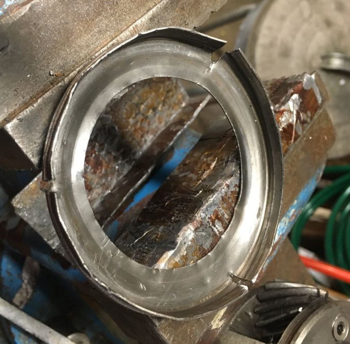

-
After my painful experience with the 1949 Desoto engine, I plan on pressure testing any flathead I am going to rebuild. I plan on pressure testing BOTH the water jackets and the oil gallery. The 1949 Desoto engine was pumping oil into water jacket. It took a year to figure out what was going on as it was a slow leak. The oil ended up in the top of the cylinder head, as oil floats on top of water, and then then the oil caused the heat to overheat and crack. If you look at a cross section of the blocks there is only about 1/4 inch or so between the oil gallery and the floor of the cooling jacket between the cylinders. Age and rust down there can lead to porosity issues and the 40 PSI oil pressure can push through it. I had an old drag racer I know suggest that I may want to use a very thin, like 1/4 inch, layer of the stuff that is used in drag race engines to stiffen the blocks. It is some kind of pour-able two part epoxy that the pour down into the jacket. His thought was that it would seal and porosity that may be down there. But the block would have to be cleaned and then acid dipped to get the rust out for that to work. Probably easier to test 3 or 4 blocks until one passes a 75 PSI oil test and a 20 PSI water test. James
