


Sam Buchanan
-
Posts
2,561 -
Joined
-
Last visited
-
Days Won
83
Everything posted by Sam Buchanan
-

Exhaust manifold nut problem--need ideas
Sam Buchanan replied to Sam Buchanan's topic in P15-D24 Forum
I'm going a different direction with the heat riser situation. The exhaust manifold will get a blockoff plate that is bolted to the manifold, and the intake will be trimmed to allow clearance for the blockoff plate bolt heads. I don't want to ever have to deal with a blown gasket between manifolds and I'm not worried about losing the preheat. I will make new steel washers where two manifold ears are secured by hte same nut. -
Exhaust manifold nut problem--need ideas
Sam Buchanan replied to Sam Buchanan's topic in P15-D24 Forum
Just to close the loop....overall it's been a pretty good day for an old retired guy: The manifolds survived in one piece, had to work them off a 1/16" at a time. Two long studs and three shorts need to be replaced, the other shorts look good. But I can look forward to drilling some studs and retapping holes....... Does anyone have a source (with part numbers) for these studs or do I go ahead and pop $70 for a complete kit? I also have a stud extractor tool on the shopping list. Thank you for the suggestions, sometimes input will stimulate the brain cells into finding a solution!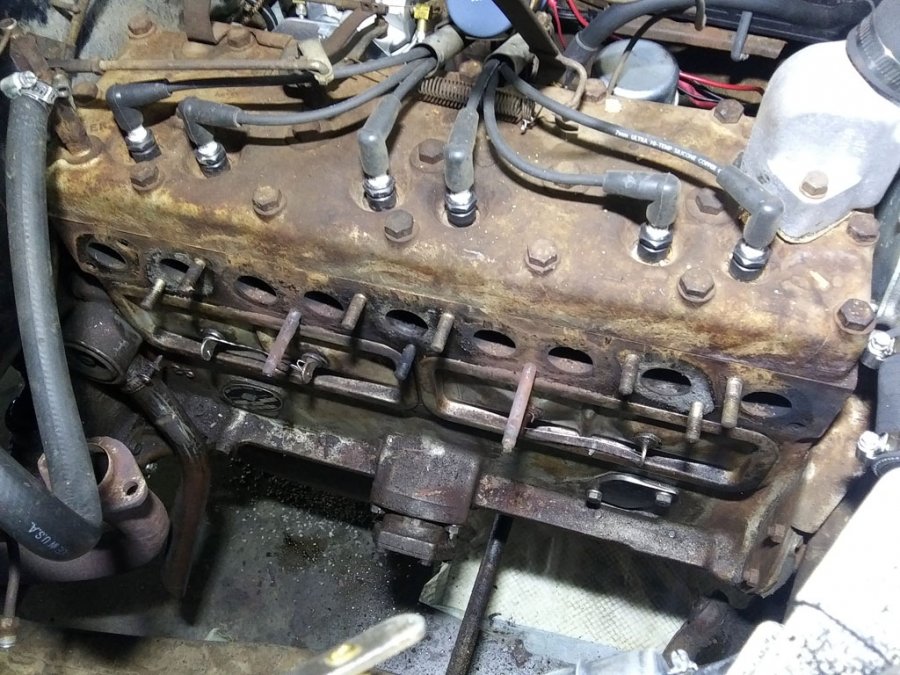
-
Exhaust manifold nut problem--need ideas
Sam Buchanan replied to Sam Buchanan's topic in P15-D24 Forum
The manifolds are stuck tight to the block. But I got the nut off. I removed the remaining fender liner (should have done this when I puller the lower liner) and was able to get a Dremel with a cutting bit into the recess. Yes, the nut is brass, MIG weld wouldn't have worked and the threads in the nut were completely gone. All the fasteners are off, now need to find a way to get the manifolds to release from the block without breaking anything. I think the biggest problem is those two lower long studs appear to be a very tight fit. I'll try a wood wedge to see it it will start moving. Thank you for the suggestions thus far!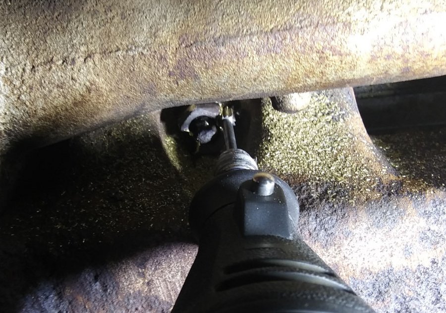
-
Exhaust manifold nut problem--need ideas
Sam Buchanan replied to Sam Buchanan's topic in P15-D24 Forum
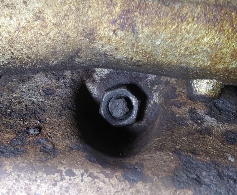
I don't think you guys understand the location of this nut. Imagine a nut in the bottom of a spark plug hole........there is no getting behind the nut......but I may try making a tool out of a screw driver to see if I can put enough force on it to make it "bite".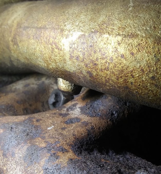
-
Exhaust manifold nut problem--need ideas
Sam Buchanan replied to Sam Buchanan's topic in P15-D24 Forum
Yes, it is lucky #13 that is causing the problem. I would love to split the nut but how do you get a splitter into this recess? -
I have a stripped nut! ? The leaky exhaust manifold gaskets on the P15 have lately increased their bark telling me they need attention. I've put this job off for a long time due to dreading all the problems that can arise. This morning I decided it was time so out came the fender liner and carb. The tally so far is two studs backed out, two studs broken off, and eight nuts removed. All four of the heat riser bolts snapped off leaving stubs in the exhaust riser. All that remains is one of the nuts on a long stud buried in the recess of the manifold. The problem is this nut is just spinning on the stud and won't come off. The other long stud snapped off. How to remove this nut in the very limited space? I'm inclined to try welding the nut to the stud then either backing out the stud or more likely...breaking it. I am open to suggestions and hope someone has a good solution. I can't remove just the intake for better access because of the broken stubs in the heat riser. I've considered sawing off the stubs but don't know if I can get to the ones next to the block. REALLY hoping the brain trust can come up with ideas......and thanks in advance!
-
And after using the "dot" to get to the first unread post in a thread and reading the threads you are interested in, hit the "Mark forum as Read" link so only the threads with new posts will show in bold text next time you visit the forum.
-
replacement solid-state Voltage Regulator available??
Sam Buchanan replied to Go Fleiter's topic in P15-D24 Forum
Install the alternator, remove the extra batteries and associated chargers, and install new, properly-sized battery cables on the one remaining battery (your cables appear to be undersize). Your car will start very nicely! If you are using a battery disconnect switch be sure it has HUGE current carrying capacity otherwise you are probably losing starting current at the disconnect. But.....if everything is fused......why worry with disconnecting the batteries? P.S. Your phone is one of the most full-featured GPS's available...... -
My First Car -- P15 1947 Plymouth Deluxe
Sam Buchanan replied to NickPickToo's topic in P15-D24 Forum
And don't use that hammer to hit the end of the puller, the Service Manual states that might damage the bearings and brake backing plate on the other side. A barefoot mechanic, eh? -
replacement solid-state Voltage Regulator available??
Sam Buchanan replied to Go Fleiter's topic in P15-D24 Forum
I was concerned about the possibility of smoke escaping so installed a fuse between the alternator and ammeter when the alternator upgrade occurred.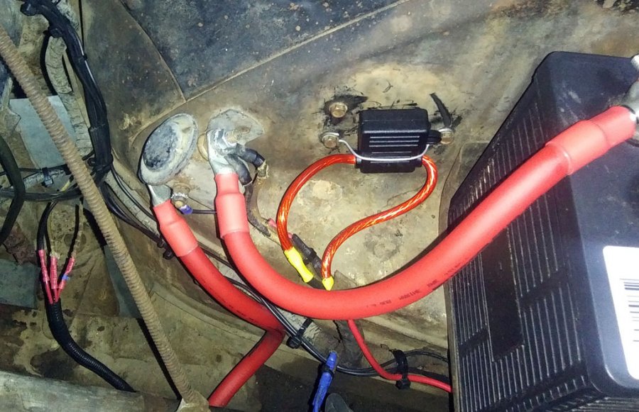
-
replacement solid-state Voltage Regulator available??
Sam Buchanan replied to Go Fleiter's topic in P15-D24 Forum
I consider a voltmeter to be more useful for showing battery condition than an ammeter. When the voltmeter indicates a solid 7.2-7.4vdc the alternator is doing its job.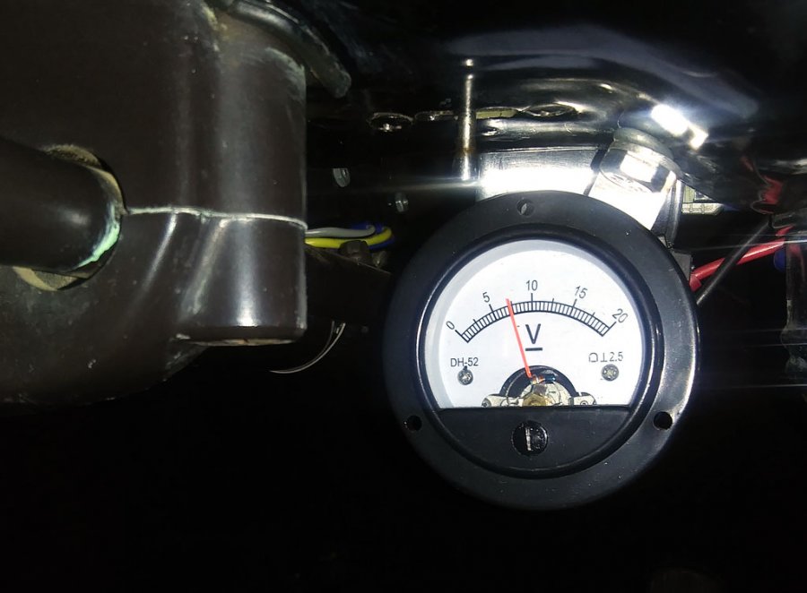
-
replacement solid-state Voltage Regulator available??
Sam Buchanan replied to Go Fleiter's topic in P15-D24 Forum
If the ammeter needle is deflected right of the center mark the alternator is charging. The meter operates, and is wired, the same way as with a generator. -
replacement solid-state Voltage Regulator available??
Sam Buchanan replied to Go Fleiter's topic in P15-D24 Forum
In order to insure that nobody is left with the impression that the alternator vendor has presented erroneous info via his circuit diagram, I wish to offer the following clarification. A careful reading of the diagram shows current path (this diagram is for a neg ground vehicle) transitioning from the alternator to the loads in the car. The diagram indicates the load path may begin with a fuse panel, or an amp gauge, or a horn relay. The current then is passed out to the accessories. In our application, the first item in line from the alternator is the amp gauge just as is the case with the old generator. This is a series circuit and allows the ammeter to indicate loads being absorbed by the accessories. This diagram is correct and allows the ammeter to show a discharge if the lights are on without the engine running. I just checked my car and that is the way the ammeter works.......but I think I would be more apt to see the headlights left on rather than a deflection of the ammeter needle.... -
replacement solid-state Voltage Regulator available??
Sam Buchanan replied to Go Fleiter's topic in P15-D24 Forum
My apologies since it is obvious you were offended by my post. No, alternators are not the ideal solution for some applications, a point I thought was made in a previous post. The wiring diagram I posted is a cut-n-paste from the website of the vendor where I purchased my alternator, I claim no originality, was just trying to be helpful for a fellow poster. As far as whether or not there is objectionable drain with a one-wire alternator or if it is even an acceptable option.......think I'll go get the popcorn popper warmed up..... -
replacement solid-state Voltage Regulator available??
Sam Buchanan replied to Go Fleiter's topic in P15-D24 Forum
That should work very nicely. -
replacement solid-state Voltage Regulator available??
Sam Buchanan replied to Go Fleiter's topic in P15-D24 Forum
Pete, connect the wire from the alternator to the wire(s) that is currently (sorry....) connected to the regulator BAT terminal. Then use the regulator as a nostalgic paperweight on your desk. -
My First Car -- P15 1947 Plymouth Deluxe
Sam Buchanan replied to NickPickToo's topic in P15-D24 Forum
? ? -
replacement solid-state Voltage Regulator available??
Sam Buchanan replied to Go Fleiter's topic in P15-D24 Forum
The new alternator cost considerably less than the $$$$'s I was looking at throwing at the antique stuff to bring it up to where it would function only partially as well (on a good day!) as an alternator. -
replacement solid-state Voltage Regulator available??
Sam Buchanan replied to Go Fleiter's topic in P15-D24 Forum
It is possible my attempt at subtle humor may have gotten lost during the trip to Denmark....... The alternator has an electronic regulator......hence he can have a new-tech regulator and as a bonus.....a new alternator! As has been mentioned, the alternator is so efficient there won't be any indicated drain, it will be able to accommodate whatever load our old cars can put on it at any engine speed. The ammeter actually takes on the function of a load-meter instead of the traditional ammeter because it indicates the amount of current the alternator is providing to keep the battery at full charge. When I have all the lights turned on the needle barely deflects to the right.....and the battery stays charged. An alternator is a great upgrade that solves the problems associated with the antique charging system. -
replacement solid-state Voltage Regulator available??
Sam Buchanan replied to Go Fleiter's topic in P15-D24 Forum
You can remove the regulator, it is not needed. The only reason the old regulator is shown in the drawing is for those who wish to keep the regulator in the engine bay for appearance reasons and it is being shown as merely a junction. But the old regulator has absolutely no function if you use the one-wire alternator. As long as the alternator is patched into your wiring with the ammeter between the alternator and the loads in the car the meter will continue to function. -
This "cupping" looks very similar to how the new shoes purchased from Bernbaum looked on my P15 after a few miles. You can see the areas of the shoe that are not contacting the drum in the photo below. I assume they are due to manufacturing variations and will disappear as the shoe wears into full contact with the drum. Arcing the shoes would be the ultimate solution but I don't know of anyone locally who offers that service.
-
replacement solid-state Voltage Regulator available??
Sam Buchanan replied to Go Fleiter's topic in P15-D24 Forum
These one-wire alternators have a built-in regulator, just connect the single wire to your harness and you are good to go. The ammeter will continue to work normally. I found the proprietor of this vendor to be very easy to deal with and eager to make sure their product works properly. You will like having bright headlights at idle speed. -
replacement solid-state Voltage Regulator available??
Sam Buchanan replied to Go Fleiter's topic in P15-D24 Forum
A reliable 6v electronic regulator is indeed available.......and as a bonus it comes with a reliable source of generating electricity: https://www.qualitypowerauto.com/item_24/6-Volt-Alternators-Positive-Ground.htm I have one.... I like it! -
Replace those squashed transmission mounts while you are in there......
-
This is getting complicated...... ? My car runs great.......I'm not the original poster. But your suggestion to check the accelerator pump is valid.

