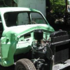
Joe Flanagan Posted March 30, 2013 Report Posted March 30, 2013 Below is a picture of the interior light switch in the B-pillar on the driver's side of my 49 Plymouth. It's got two terminals (I know the photo is blurry). According to my wiring diagram, only one wire goes to this switch. I've attached the wire to each terminal and it does not work. When I take the bare wire and touch it to the B-pillar, the light goes on. I believe the switch works like the horn and just provides a ground to complete the circuit. I believe I have the light wired correctly but I'm confused about the two terminals on the switch. The automatic switch on the passenger side doesn't work either, so I may have gone wrong with the wiring somewhere. Quote
Young Ed Posted March 30, 2013 Report Posted March 30, 2013 I've seen switches with only 1 terminal. I think thats what my p15 uses. Have you tried the same grounding test with your door jam switch? Quote
Joe Flanagan Posted March 30, 2013 Author Report Posted March 30, 2013 No, Ed, I have not tried that. The door jam switch has only one terminal, though. Quote
Young Ed Posted March 30, 2013 Report Posted March 30, 2013 I think your pillar switch should match then. Try rotating the door jam switch to see if that gets it working. Mine was dirty from sitting for so long and spinning the button got it working again. Now that its been in and used for a while its gotten better and better. Quote
DCurrent Posted March 30, 2013 Report Posted March 30, 2013 (edited) If I understand correctly, contacting the bare wire to the post turns the light on. So the switch should let the wire ground to the post. Use a multimeter to see if either contact on the backside will complete the circuit with the frame of the switch. Edited March 30, 2013 by DCurrent Quote
Joe Flanagan Posted March 30, 2013 Author Report Posted March 30, 2013 The light does work when you touch the bare wire to the post. Quote
Oldguy48 Posted March 30, 2013 Report Posted March 30, 2013 Perhaps that switch is not the correct switch. Try grounding one of the terminals, and connecting the existing wire to the other terminal, and see if it works. You could just hook it up with some alligator type test leads for a quick test. Wayne Quote
DJ194950 Posted March 31, 2013 Report Posted March 31, 2013 Joe, your car has a full time hot to the interior light. Test this at the light socket. The switches only provide a Ground to the light either thru the door post push button type switch or the on/off B post switch. Some switches only have 1 wire and the other contact is thru the body of the switch. Switches with 2 contacts-- Wire one of the two (either) to the mounting screw of the switch. Most of the factory door switches where of the self grounding of the body many after market switches often had 2. Clean the mount area for a good ground and was mentioned in a previous post, work the switch in/out/ turning/ etc to try to get a good Internal contact connection. Best to ya, Doug Quote
Joe Flanagan Posted March 31, 2013 Author Report Posted March 31, 2013 (edited) Doug, I rewired the car completely and yes, there is a full time hot connection to that light. If I understand you correctly, I should run a short wire from one of the terminals to one of the mounting screws of the switch. Seems to me there would be no way to hide that wire, though. Thanks for the other replies, too. I'll try your advice tomorrow. Edited March 31, 2013 by Joe Flanagan Quote
Oldguy48 Posted March 31, 2013 Report Posted March 31, 2013 Joe, You could just solder a short length of wire from one of the terminals to the body of the switch. Then that terminal would be grounded when the switch is reinstalled in the B pillar. Wayne Quote
Joe Flanagan Posted March 31, 2013 Author Report Posted March 31, 2013 Thanks, Wayne. I was just thinking of something similar myself. Quote
DJ194950 Posted March 31, 2013 Report Posted March 31, 2013 Doug, I rewired the car completely and yes, there is a full time hot connection to that light. If I understand you correctly, I should run a short wire from one of the terminals to one of the mounting screws of the switch. Seems to me there would be no way to hide that wire, though. Thanks for the other replies, too. I'll try your advice tomorrow. Thinking about the switch install i did about 1-1 1/2 years ago i think? that i actually ran a grounding wire from the connection to another hole i drilled in the B post and installed a screw. I think there was room in the B post hole for the switch to mount the wire outside on the post. The switch and cover probably were installed on top of the upholstery on the B post making my original post a sometimes iffy ground thru the switch mounting screw. Anyway i see that you get what needs to happen and you'll figure it out to suit yourself from here. Best Doug Quote
Rodney Bullock Posted March 31, 2013 Report Posted March 31, 2013 Hey Joe, your switch has two wires because one goes to the light and the other goes to the power source. The other pillar has one wire because it should be a direct connection from the other side. The light fixture itself is grounded and so is the switch. remember 6 volt pos. where it's grounded it's getting power. Quote
Joe Flanagan Posted March 31, 2013 Author Report Posted March 31, 2013 Success. I did as Doug suggested and mounted a wire from the switch to the B-pillar. That completes the circuit when the switch is turned on. I don't know how it was done originally, but this works. Quote
DCurrent Posted March 31, 2013 Report Posted March 31, 2013 I'm not sure if this is the way they wired it from the factory, but don't forget about the light in the "ON" position or the Battery will be dead. Quote
Labrauer Posted April 1, 2013 Report Posted April 1, 2013 I had the almost the same problem with my switch. I very carefully took it apart and found that the (I guess) copper slid bar had some corrosion on it so I used a finger nail file of the wife's and filed the terminals. Put it back in and it worked just like new. By the way that was the one on my P15 and it was the two wire terminal too. Just a thought and my experience working on mine. Quote
Joe Flanagan Posted April 1, 2013 Author Report Posted April 1, 2013 I took mine apart too, and cleaned it up. It was a lot of fun putting that little thing back together. Quote
Don Coatney Posted April 1, 2013 Report Posted April 1, 2013 I few years ago I bought a NOS switch from Neil Riddle aka Plymouth Cafe on the bay. Cost was low and he may have more if you need a replacement. Quote
Young Ed Posted April 1, 2013 Report Posted April 1, 2013 Or you could just buy a few off ebay like I did Quote
suntennis Posted April 1, 2013 Report Posted April 1, 2013 Someone installed the wrong switch,but you can as suggested make yours work. If you have a service manual, it shows the wiring is different for the dome lite prior to 1949. Earlier cars used a dome lite that was a single contact single element bulb that was grounded at the lite fixture. Your car uses a dome lite that is a double contact single element bulb that is grounded by the switch in the pillar. Quote
48ply1stcar Posted April 5, 2013 Report Posted April 5, 2013 The switch looks correct. My car is 48 P15 and I just removed the original wiring from my car this morning. There were two wires to the pillar switch and two wires to the door switch. Quote
48ply1stcar Posted April 6, 2013 Report Posted April 6, 2013 I hope that I can explain the wiring without a diagram. The dome light is wired like three-way switch in your house. When the door is open and the light is on you can turn off the light with the pillar switch. When the door is closed you can turn-on the light with the pillar switch. So like in your house that one switch (pillar) doesn't really mean up for on and down for off. Now with that said that I'll try to describe the wiring. Power from the dash is spliced and sent to each switch. An additional wire starts from the opposite terminal of the door switch and runs to the dome light with a splice to the pillar switch. In your house you would use three-way switches and run the wire to the additional terminal instead of splicing the wires. I Googled "DC three-way switches" and found diagrams for this set-up. OR On the botom of the picture you can see the rear wiring harness starting from the dashboard. The splice is made and power is routed to the door switch and the pillar switch. Then the other wire starts at the door switch to the dome light with a splice to the pillar switch. Quote

Recommended Posts
Join the conversation
You can post now and register later. If you have an account, sign in now to post with your account.