-
Posts
197 -
Joined
-
Last visited
-
Days Won
8
Everything posted by Semmerling
-
I'm not confused any more...there she blows..
-
It may just be me but I cannot see the photo that you posted
-
I must admit that now I'm really confused. If in fact you were able to make it home (with the car operating normally) using the electric fuel pump then, may I assume that you could not make it home relying on your mechanical fuel pump? If that is correct then I agree with Sam.
-
The short answer is yes, in fact in this case, the gaskets were used three times and could be used again. The foot pounds on the intakes is 20, that's so low one has to stop and think about it because normal experienced hands think of "reasonable tightness" at around 35.
-
Sam, you are of course right being able to disassemble everything in 30 minutes is dependent on the state of everything involved. There was no prior owner other than my grandfather than my father now myself working with my son. Having said that, I would make the case that if in fact you are confronted with an engine that can't be taken apart, that may very well be the very best time to take it all apart and begin the process of improving the general condition. In the case of the 34 one has no choice the inner fender liner is welded to the exterior fender and there just is no other way to go about doing the work.
-
That would be my experience. The only issue we all contend with is that the disassembly, adjustment, reassembly and test driving may end up with the recognition that you have to do it all again. Only then does it become more of a pain. Having said that, one does this so infrequently, the opportunity to have a perfect set is worth it.
-
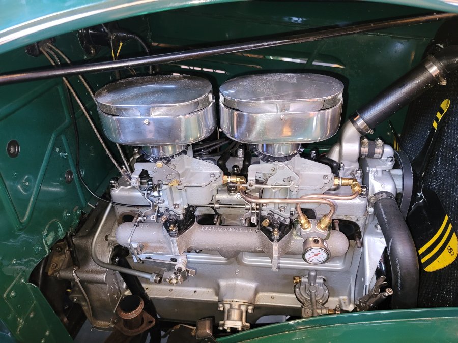
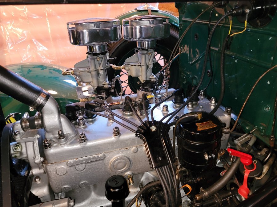
One of the interesting differences between the 1934 model and all of those that followed is the design and location of the throttle actuator. On the 1934 model there is a rod that goes from the gas pedal all the way across to the passenger side on the firewall in the engine bay. What this means is that the later model throttle actuation that goes over the top of the engine block head to the carburetors it's not how the early model works. The 1934 model has an onboard the intake manual actuator that not only attends to throttle acceleration but also provides the means for the dash mounted throttle adjuster to work as well. The vast majority of George Asche installations that I have seen both of the later accelerator actuators and also they do not appear to support the dashboard mounted throttle adjuster cable. I wasn't willing to give those up so I went about the Asche carb set up a bit differently. I actually used both sides of the new intake, with the linkage that moves both carburetors in synch being on the engine block side and I use the provided pad on the passenger side to reconfigure the whole standard actuator including the dash throttle in a brand new design. I thought that resulted in the nicest presentation and preserved all of the features of the original. Now you can't use the original throttle actuator and the reason for that is the original one pushed up on the carburetor and the one that we use for the Asche model pulls down. When I finish this whole thing I'll do a full feature right up thread. What you see here is are 2 photos of the fitting and testing of the new linkage. For those of you who may have read my piece about accessing the valves by taking all the intakes off, that was done originally so I could get everything out of the way and remount the Asche intake to test fitment. I originally decided while everything was off I would redo the valves. Anyway the new design will now be taken from its original aluminum modeling you see here, to pita to make stainless steel throttle actuator. Astonishingly. Both the choke and dash mounted throttle cables along with the firewall actuator rod all fit perfectly. That never happens around here and required us to sit and stare at the intake because we just simply couldn't believe what we were looking at. Anyway it all is a step in the right direction. Just note, the bright large diameter tube in the lower left hand corner is the vacuum line for the 34 and it's just sitting there disconnected.
-
- 2
-

-
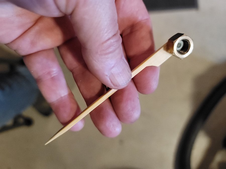
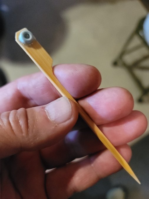
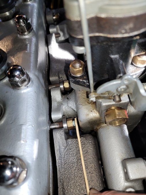
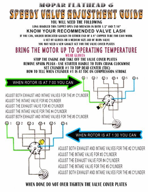
For the early Dodge models that do not have an access panel in the passenger front fender to get to the valves there is only one way to comfortably adjust the valves. I was able to completely remove all the manifolds and get enormous access to the valves in less than 30 minutes. As far as I'm concerned, there's no more mystery, valves were adjusted in the early models by removing everything in the way. It took me less than 2 1/2 hours to access the valves, fully adjust them using this Speedy Guide I published a month ago and be back on the road. Now what this means is, the early engines are best adjusted cold. And since there is literally no published data as to what those COLD adjustments should be, I actually took apart the engine and adjusted the valves twice, once in the late afternoon and then early the next morning so that both blocks were cold. Access to the valves was fantastic. Given that, I have a couple of observations. One has to remove all of the time intensive operations, and the ones that are most time intensive are the ones that deal with having to manually put on washers and nuts on studs that are in very difficult locations to access. Given that I'm going to show you a very simple tool I created in order to thread the nuts that are on the center intake. This works for both the top and the bottom and literally lets you get them all on a minute or two. The second observation is that at 20 foot pounds the intakes themselves should be checked regularly even if you're not taking them off. I would say approximately 40% of all of the nuts needed a tightening. So with that let's start with the simple tool. It's basically as you see in the photos with the rubber nib being of a smaller diameter than the ID of the nut to the point that once you get it on the end of the bolt, you just spin it with your finger. It works perfectly with the recommended brass nuts. I'm happy to answer any questions that people have. In the case of my 1934 Dodge Dr the Stone Cold Lash adjustment numbers provided the quietest and best driveability the car has had. The manual states that the 1934 has an intake of .005 adjustment, and an exhaust adjustment of .007. These are obviously much less than the later years. Given that I use the 0.002 ADD rule for a cold engine bringing those numbers to intake .007 and exhaust .009. I used the Speedy valve guide that I published about a month ago and everything was done with one rotation of the engine from number one cylinder to number six. Folks. The guide works. I wasn't completely satisfied. I drove it originally, and thought it could be better both by way of the sound of the valves and drivability. I did the first set in the evening and I tore the engine down again the next morning and reset the valves at intake 009 and exhaust 011. For my block this was by far the very quietest and best driving valve adjustment I think the car is ever had. So there it is, cold setting for a 1934 Dodge Dr that was slightly decked is intake .009 and exhaust .011. I'm happy to answer any questions.
-
Photo is in color and reasonably focused so we have to rule out is being a UFO. What ever you do, do not take it out of the trunk and take a clear shot of it in good light. When that happens these things morph into a spare pre stage heavy dust air filter. P.S. It can't be a plumbus, its is cross stitched and has neither a sleeve or cortell.
-
I would also tell you that for about 10 to 15 years Auto clubs would have color combinations specifically for that club. They were called Flags. I remember you could walk around and basically know if a car was from Brooklyn or the Queens. As soon as shrouds came, that all disappeared. Interestingly though, Hot Rodding picked it back up in the early 50s for a good number of years.
-
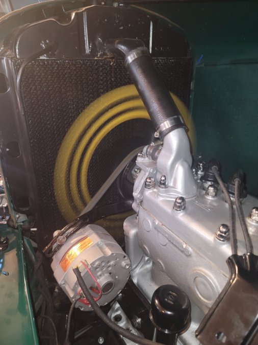
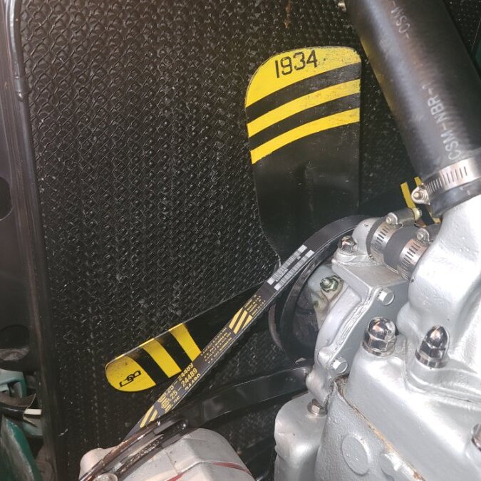
Yes that's the year of the car. It's relatively easy to do, first you put down painters tape on the areas that you do not want the spray paint to cover. If you look at mine, when the tape was down, the tip and the other two bars were open to be painted. Go down to any hobby store and get typical adhesive back paper letters. Home Depot sells them in many different sizes. Carefully place them on those very same open positions and then spray everything open with a quality spray paint. Give it about 5 minutes of drying, and then, with a pin, lift the letters back off and the black will show through underneath.
-
Interesting, I was going to write a short thread about the process of "Bumblebeeing" the fan blade but figured it was too light weight for this place. Many of the people including my grandfather, took the time to do this....Eglin Field "pink mist" makes a powerful case.
- 27 replies
-
- 10
-

-
On every case casting there is a number. If you can read the number, post it and there will be no mystery.
-
The only time I every heard about anybody ever having real trouble was a friends with a super common name like Donald Clark. He was fine getting into Canada but upon the return they ran his name and it came back on the terrorist list. He and his elderly wife were separated and he ended up spending 3 days in super max confinement before he was sent to guantanamo bay were he contracted Covid. It took a Congressman 14 weeks to get it all straightened out. They returned him to Boston where he got on the MTA and was never seen again. They say he is still on it. You should be fine as your name is nothing like Donald Clark.
-
Love the optimism! A coupe new parts, bearings at a minimum, atf and a wire brush! And.....it's over. Unfortunately, it was the transmission, now it is a mooring anchor. A rare transmission can take 2 years to source everything for a complete rebuild. You are luck as your's is not rare, do not waste any time on it and start over. You will have something worth the time, effort and $$$$. Why ruin a perfectly good wire brush?
-
The 1934 Dodge DR did not have the much improved removable inner fender access panel found in later year Dodges that allowed proper access to make valve lash adjustments. The 1934, like most of the early Dodges, has terribly constrained access. One cannot improve the situations by going in from underneath and removing the engine drip panels. Nor will removing the spare tire, it's cover and support bracket. Removing the whole fender is a way to gain barely enough access, but it is quite a job as the inner fender is tack welded from the factory and removal requires taking off many surrounding parts. Damage is possible and four hands is recommended. Having said all that, if one wanted to do the valve adjustments with a fully hot block, well, it is not going to be pretty. So how did the valves get adjusted both back in the day and what is the right approach for now? COLD adjustment now becomes the best path forward when working on the early Dodges The main reason is because the cleanest, most direct way to attend to the adjustment is to take off the exhaust manifold (and the intake manifold) in order to gain excellent access. So.....now the big question....what would one use for the correct COLD valve valve lash? The answer is "a tight .002 over the recommended HOT valve values" for the 1934 Dodge DR and DS. But, it has to be a "tight" .002" add-on. That means that the feeler has to just barely be able to get into the gap. A normal .002" is the standard for cars with longer valves, like a Packard. The Dodge actually needs only .002" and no more. The 1934 Dodge's Factory Maintenance Guide listing out the following for HOT valve clearances: HOT valve clearance 1934 Dodge DR and DS INTAKE is equal to .005" EXHAUST is equal to .007 First, we need to note that these recommended clearances are tighter than for the years that would follow. Many rebuilt engines for the 1934 have been decked and therefor the clearances are actually tighter for the valve to travel in. Equally, many of those same rebuilt engines are set-up using the later (and looser) INTAKE=.008 and EXHAUST= .010 clearances. All of these can be a recipe for new set rebuilds to be found to be making noise soon after being broken in. Second, to do the valves COLD we would add the for mentioned "tight" .002 to both the HOT INTAKE and EXHAUST clearances. COLD valve clearance 1934 Dodge DR and DS INTAKE is equal to .007" EXHAUST is equal to .009" With that all out, One would need to ask where did these numbers come from? The HOT adjustment numbers come from the Factory Manual. The COLD adjustment numbers come from asking everybody I know that have spent time with the 1934 DR. Of those people that would or could provide an answer, they agreed that taking off the manifolds and doing the engine STONE COLD with the COLD numbers provided above is the best way for this year. One of them is so proficient at taking off the manifolds, he says he can do them "hot enough" to use the HOT numbers. He uses air driven tools to take off the manifold as its all about speed and manual typical hand tools to put it all together. He too recommends that "just do them cold" is perfectly fine as well.
-
- 1
-

-
And first 2 post gets to the Admins only.
-
Transmission number from the casting will tell us how rare the internals might get to be. Left side....right side.....topside.....bottom.....inside pics. Looks like it filled with water and then froze.
-
Static timing rotor at 6:30 not 7:00 on 48 DeSoto
Semmerling replied to MarcDeSoto's topic in P15-D24 Forum
I really appreciate your videos. Whenever I come across one, regardless of topic, I stop and give it a watch. I know how much time these kind of things take, so thank you. -
Zounds....what a nice car
-

ADJUSTING VALVES - MOPAR FLATHEAD 6 - Speedy Guide
Semmerling replied to Semmerling's topic in Technical Archives
Glad to hear that it all came together. I would be interested in the following: When the engine was warm and you did some fine tuning on the valves that you set cold at .010 and .012, what did you find? - How much off was the final warm adjustment - Did the intake valves pretty much hold true and the exhaust valves need the attention? Thanks, -

ADJUSTING VALVES - MOPAR FLATHEAD 6 - Speedy Guide
Semmerling replied to Semmerling's topic in Technical Archives
Only thing that would come to mind is that your distributor wasnt set into the block in the proper rotation. Do this... Look at your head near the fire wall. Near Cylinder #6 (closest to the firewall) there should be a small plug that you can take out. That is directly over the #6 cylinder. Get a long thin and straight wooden rod that can easy slip into that hole AND WONT DROP IN and it will rest on top on the piston Rotate the fan and that stick will eventually rise to TDC. Look at your distributor, the rotor when that stick is at its highest should be at either of the two point shown in the diagram. You want to rotate until it is at TDC and the rotor is at 7 to 8ish. Then #1 (nearest the fan) is ready and you can get to work. One full 360 rotation will get you to stick up at #6 (firewall) and you can do the rest. If your distributor has the stick UP at TDC and it isn't as shown, your distributor was improperly set into your block. -
If.... -You took out all the plugs to remove the compression when you rotated the fan blade -When you took the distributor cap off, you weren't confronted with a loose distributor able to rotate. -You were concerned that you might have not been exactly TDC, but you know you were at least close -You took the time to check the rotor to be sure that it was at least on the right firing position -You used the right feeler gauge and you tightened the valve adjustment properly - And, not that one has to, you didn't pull the over piston #6 plug and use a TDC rod? - When you adjusted the valves you were not confronted with valves that were WAY out of order -By the time you were finished the engine was cool. -When you tried to restart the engine, the issue was it didn't start..not clanking and banging. right? Check your spark plug wires at the plugs for connections....at the cap for tight contact and right order. Check the rotor contact surface to make sure wasn't accidentally greased. If it was, clean the cap too. Things to consider: Distributor wasn't properly timed when set into the engine.
-

ADJUSTING VALVES - MOPAR FLATHEAD 6 - Speedy Guide
Semmerling replied to Semmerling's topic in Technical Archives
GREG G.....I struggle with the layout here. What follows is meant to be helpful. DOWNLOADS: POTENTIAL TECH HOW TO REPOSITORY #1 Downloads is dissimilar to any other section here. It looks like a place to store static graphic, got that. The issue is the layout and the selectable filters on the right make no sense at all. I loaded stuff in there and had difficulty navigating back to them, literally vanished and took time to find. The same images appear on that header page regardless of how old they are, leave and come back and the same old images are there forever it seems. A straight up Chronological last loaded would work much better and the typical search would as well. No idea how to get that section to do anything that makes sense. A place to see scanned images not anything about "How To Get Something Done" except for scanned static manuals etc. TECH TIPS: POTENTIAL HOW TO TECH REPOSITORY #2 Static single load with no seeming way to enter anything new, make corrections, observations, etc. . Odd order, unsearchable. Just don't get it. The actual data in there is good but without direct comments very limited one time stop. I did the adjusting valve illustration from that data because, as presented, it raised more questions than answered them, RESOURCE - MAINTENANCE: POTENTIAL HOW TO TECH REPOSITORY #3 Getting weirder now....all static loads....again. Not searchable and not in any meaningful order That section needs to be added....somewhere....and flushed away forever...just about useless. Nothing their but a single page read. Just don't get it. TECHNICAL ARCHIVES : POTENTIAL HOW TO TECH REPOSITORY #4 So...I dropped it here...in something called TECHNICAL ARCHIVES Chronological Build and searchable. Makes sense, people can interact and stuff can be found. In short..... Keep a single Image location: Make it so that the newest is shown when a viewer arrives to the page. Make it searchable. Keep a single technical section for each major already existing model/year whatever here at P-d. Make it chronological and searchable as well. Move the material from the other two and flush them....way too complicated and confusing. Thanks for reading this far.


