-
Posts
197 -
Joined
-
Last visited
-
Days Won
8
Everything posted by Semmerling
-

"One of these things is not like the others..."
Semmerling replied to Bob Riding's topic in P15-D24 Forum
Bob, I had my original radiator completely cleaned when I rebuilt the engine in 2021. What came out was much more than I expected. Pressure tested and painted, it now runs in the lowest range I have ever seen on this rig. Because of that,. I have not ever moved to a more modern radiator. One of those radiators in your pic may be all that you need. -

"One of these things is not like the others..."
Semmerling replied to Bob Riding's topic in P15-D24 Forum
Thank you both for the stand information -

"One of these things is not like the others..."
Semmerling replied to Bob Riding's topic in P15-D24 Forum
Bob, what brand is that engine stand please? -
How about this? Send them a message. https://www.ebay.com/itm/401380303625
-

"One of these things is not like the others..."
Semmerling replied to Bob Riding's topic in P15-D24 Forum
I agree, beautiful job on the engine -
Thanks.. Gas line off Both vacuum lines off Choke off Waste line off Air filter off Accelerator actuator to linkage off Exhaust to intake Tower bolts out Intake off Exhaust to tail pipe off Exhaust manifold off Sparks out Distributor cap off Valve Covers off TDC plug out Every valve set using the 2X rotation system All reassembled 1 Hour 48 Minutes total...down from 5 hours plus first. That tool was good for 10-15 mins right there alone. No doubt, that is how the early years addressed the valves. Gorgeous access.
-
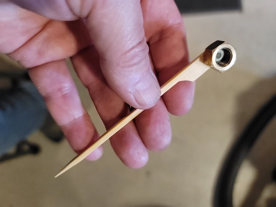
The fastest way to mount all the brass nuts on the center intake studs. One places the nut on the blue hub and then set the nut on the end of the std. A quick spin and the nut threads right on. All three washers and nuts on in under 2 minutes.
-
Sniper we are all just having fun here. Health is the whole game. Get better asap....you are part of the best read here.
-
I use them all the time but they are not the brittle cheap ones. Those like poor quality aluminum terminals run a much higher risk of failure. That must be the new apple watch....nice! I do still want to see Snipers movie though.....I've done some soldering myself and its got to be better than Netflix Cleopatra...... .
-
There is nothing wrong with crimping but one has to know what they are doing. As those have already stated, Quality wire, Quality connectors and terminals, Quality crimp tools all make crimping good enough to be used in the most demanding equipment for the most important military and space applications. Good quality parts and skill and it works perfectly. I agree with the thought that the cheap brittle plastic insulators is trouble waiting to happen, one is truly better off shrink tubing than using those types of terminals. I use bare terminals, use the right type of compression and then slide up heat shrink to insulate. Most people do not have access to good terminals and connectors, nor the crimping tools to properly do the job. The suppliers are cheap as can be, a terminal costs a fraction of a penny. What people pay for a crappy hand crimper is what a very good hand crimper should go for. For those that know electrical connectors and fart dust like me, the man on the far left is Bern of "Burndy." Anyway....toss the plastic insulators so you can use the right crimping tools and then insulate with shrink. Solder does an excellent job but then there is the issue of the Shemp like "Knack, Yuck Yucks" and whole dropped testicle thing.... The pics of the poorly formed brake/fuel bends. Bending radiuses that tight cant be done with, once again, the tools most people will come across locally especially if the end is to be fluted. Still, when that happens it should be pretty clear there is a problem and one gets the tool...and or perhaps glasses. Knack....
-
I enjoyed this thread, many thanks.
-
they are the wrong plug. Champion was/is recommending a "10-11" heat range for the mid '30s and forward. They are recommending a J11C (RJ12C if you have a radio) for a cast iron head. Both gapped to 0.025. Aluminum head uses is a recommended H10C...with radio its RH10C. Again both gapped at 0.025 I was surprised when the subject of bargains on the J8Cs came up as I have plugs here going way back and the lowest is an 11. Given that I called them and asked and the guy with the most history there, he said that it was never J8C.
-
This is a perfect example of something that well written and topic specific enough that it should be recast in its own thread with a searchable title. Thank you for putting this out here
-

...back off piston by turning engine with fan.
Semmerling replied to DonaldSmith's topic in P15-D24 Forum
Scratch this one off the list...... Leaving the transmission in gear with the engine off does not lock the rear wheels. A fluid coupling car left in gear with the engine off will roll just as if it were left in neutral. Therefore, maintaining the emergency/parking brake is paramount, and care should be taken when parking the car when anything but absolutely level road conditions are encountered. -

...back off piston by turning engine with fan.
Semmerling replied to DonaldSmith's topic in P15-D24 Forum
So I'm going to try to help here. Perhaps like others, I'm not quite sure what this thread is about. At first I thought it was a discussion about why you couldn't rotate your engine by turning your fan and even there I can't figure out whether it's always been that way or it's a new phenomenon. Then I began to believe it may about the failure of another Pertronix unit and the impact of swapping back in points.... whether in doing that and timing it properly at the oil pump, you may have created a mechanical bind problem. Then there was the part about what constitutes top dead center and how we can't be sure that the distributor cap is pointing to either cylinder one or Cylinder 6 as it is now newly installed. And then there was a discussion about a late 40s automatic transmission as potentially being the culprit. I don't know which is more concerning, you having to go through this, or me not really being able to help you in any way. Having said that, I'm going to try. 1st.... Is your car in neutral? If you jack up the rear wheels do they turn or are they locked in gear? If Yes we move on, if no that's that's where you need to start. -
Tighter is Higher, you are right. Less travel and lower valves. Intakes are adjusted to take the charged mix and it get fully into the combustion chamber in the brief period it is open. No more that that is need, especially in a single atmosphere engine. The exhaust valves require more attention as they have a much more complex flow problem in a flat head. " I have seen some engine specs showing .016” hot exhaust setting for the 25”." First off one would ask hot or cold setting? If its hot that is quite a gap but if its cold it is at .014....see more below. So think of the valves as having the full force of their springs dedicated to keeping the valves closed. TDC is where one finds a cylinder in a state where there is no tappet force present on the valve and the full force of both the exhaust and intake valve springs are at work keeping it closed in full charged compression. That is why one can so easily rotate the tappet....it isn't engaged by the crank....nor is it touching the valve. The gap is at its widest at TDC. The crank rotates and lifts the the valve by moving the tappets upward. If the valve went all the down to interface with the crank, as in no adjustment, the whole potential motion of the crank would be transferred upward to the valve, this would be the maximum potential lift. But if we place an adjustable tappet between the crank and the valve we can adjust the full lift to be less travel by shortening the tappet length. That "shortening" is the gap...In other words the tappet travels through that "space" I mentioned without touching the valve before moving the valve upward. Shorter tappet = lower lift to the valve. Intakes are cooler, they do not experience the extreme heat of the exhaust valves Intakes open up to allow the charged atmosphere to enter the combustion chamber and then need to close up. Intake settings are normally found to require less gap for material expansion (stretch) as the charged mix is its self a cooling event. The original factory setting for the '34 intake is .005 that is pretty tight. Exhaust valves are hotter Exhaust valves have to open up to allow for maximum hot post combustion gasses to exit. Exhaust valves are normally found to have more gap both for material expansion and expanded gas volume. Exhaust valves set too low, so that they do not open enough to allow for maximum exhaust discharge, can quickly overheat and can potentially badly damage an engine. Exhaust valves for a car that routinely is driven long distances have their exhaust valves set at the max gap allowable. Head Hitter is a metaphor, like Lobe Polisher. Or...."Better to Hear them than Smell them."
-
All new valves and the tap it contact contact surfaces look good. I opened up the exhaust on the last pass pass both the safety measure and a final attempt for quiet and it seems to have really made a difference. Striking the heads...I was curious if anybody would say something. Thanks for reading that far down.
-
Great question....here we go.... Most people adjust their valves by following the exact specifications in a factory manual. But, there is more to it than that. The factory manual may say. "All adjustments are made on an engine that has reached operating temperatures." In other words, don't warm up your car...drive it until it is at true operating temperatures and THEN adjust the valves to what is essentially a recommended "GAP" between the valve and the lower tappet. The problem that people without easy access to the valves have is that we cannot actually get to the tappets to adjust them. We have to take things apart. And therefor our engines are not really at operating temperature. So we use COLD setting numbers that take into account that the valve and its actuators are shorter when they are cold and will lengthen/'expand as they reach operating temperature. COLD adjustment numbers require a larger gap... OPERATIONAL GAP WHEN THE ENGINE IS HOT FOR A 1934 DODGE DR Intake = .005. EXHAUST = .007 But, because we cant actually get there in time we need something more (wider) than that to account for metal expanding So we ask around to those that might know and, in my case..... 1. Nobody really knows and I asked some very knowledgeable people and they said things like "the general rule of thumb is that one would add .002 to both the intake and exhaust numbers for a cold lash adjustment." Or another solid mind said "Swig, look the valve stems in the 1934 Dodge DR is only a modest affair, they do not have the length or mass that, say, a Packard valve has with its longer stem. You should try a tight .002." So , we would end up with something like this.... OPERATIONAL GAP WHEN THE ENGINE IS COLD FOR A 1934 DODGE DR Intake = .007 EXHAUST = .009 Now I did exactly that....and since I could have laid a ham sandwich in the open tappet bay it was so magnificently open, my adjustments were perfect. I gave them a tight (pinchy) adjustment. Then I rebuilt everything and went out for a ride. The end result was too much valve noise (Valves moving up high enough to strike the head.) Was it better, yes. Was it good? not really is was OK. OPERATIONAL GAP WHEN THE ENGINE IS COLD FOR A 1934 DODGE DR Intake = .009 EXHAUST = .011 So I tore it all apart and readjusted using more gap (wider) so that the travel of the lower tappet went slightly long through space before pushing the valve up to a lesser height. And then I buttoned it all up and went for a real drive. Was it better...oh yea. Was it good? It was good but I had residual strikes though much less of them. So I tore it all down and went to work.... But then it got interesting, I learned the following. One of the reasons the 1934 numbers for gap is smaller than even 1936 is that the "they" of yester-year came to find that the 1934 numbers had made the exhaust valves run hot. And I told myself that decking might have narrowed the space the valves had to move in and then there was new pistons, better valves, etc. etc. OPERATIONAL GAP WHEN THE ENGINE IS COLD FOR A 1934 DODGE DR Intake = .009 EXHAUST = .012 And.....it was really good..... Now All I have done is to get the valves to use the space it should. Now comes the question of timing. I have some more work to do on other elements on the fuel side of the equation before I can address that issue.
-
This is all about how to fully dismantle the complete intake, the exhaust manifold, spark plugs, etc. etc. to gain enormous access to the valves. And how one can take everything apart....adjust lash....and put it all together in less than 2 1/2 hours. Now we talked about this, in my case the '34's inner front fender is welded to the outer fender shell and there is no access panel to view and do the valves. All the tune-it up live folks are SOOL (the last "O" and "L" stand for "of luck). How is that possible? Valves aren't done very often and when you get a good deal of experience you can take it all down, tune the valves and reassemble in under 2 1/2 hours. BUT...you have to know the tricks and order of things. As importantly, one is doing a stone cold adjustment and their is no factory data on cold numbers. The most often used "add 002" to the "operating temp tune" numbers didn't really work. Ever less fortunate is that, in order to really dial in a motor that has been changed (decked, improved pistons and rings, etc.) you have to break it all down....tune it.....set it all up.....and run it....come to realize that it is "good" but not "really good"....break it all down....adjust it.....rebuild it.....run. As a result the few folks that have the early rigs really never get a great valve adjustment, and here it why. Nobody but you is going to take the time to do it properly. One true benefit of this is that one gets to revisit every part of the of the manifolds and it can be a tremendous opportunity to make things truly right. Remember....this is all about the years that one cannot go into the fender port..... The process or deconstructing, tuning and reconstructing for a really skilled person is approximately 2 1/2 hours, but that person knows all the trick, traps and the order of thing. The first time around, you will most likely do it more than once for a really perfect valve adjustment. It would take a special kind of shop to do this cycle more than once on an early car left with them. It will not take them less than 2 1/2 hours. It is also likely they will most likely use the standard "add .002" to the 1936 onward factory spec. If the engine is stock and in great shape, it may be a close. If the engine is older, reworked, "improved" my experience tells me it won't be a great valve adjustment. With a reworked top end with new parts, well it takes a couple of adjustments to get the valves and timing right. I can tell you this. Sitting in front of HUGE room and a nice line up tappets is really a sight. I should know, in the last week, I have done it four (4) times. I can truthfully ay the process went from 6 hours to less than half that. I would also say that I am not not done....all of this work was done prior to a dual carb build and new exhaust system and in order to tune that I expect to revisit timing, but have dialed in the valves, reworked fuel deliver and pathing, vacuum access and delivery, etc. etc. etc. I thought before I forget how one gets the process to 2 1/2 hours round trip, I would list out the highlights.... 1. If your block is a mess, if your intake and exhaust is a mess by way of fasteners, gaskets, mating surfaces, fuel delivery, fuel line runs and fittings....you are done doing this work quickly. This topic came up in an earlier thread and the comment was correct, more parts run the risk of being destroyed. Valve lash is only one of a whole number of things impacting those engines. There are four (4) bolts coming up from the base of the exhaust heat tower into the intake....these cannot be crapped out. 2. Tricks - All the nuts used on the intake and exhaust are brass. All the washer should be thick and stainless. The kits you see being sold with dinky regular flat washers, even if they are stainless, is really a lousy deal. Those sets are tremendously overpriced, just plain ridiculous. Plated thin washers? No mention of what the studs are? Even the pictures show corrosion in the offerings. Get brass nuts at any maritime store. I get the thick stainless washers on EBAY. The studs should be in excellent shape and the nuts should just thread right on them. The gaskets should be able to take a number of on/offs (I am up to four) as there is no tearing or wear and the torque is LOW at only 20ft lbs. In fact, for those that never visit this side of the engine, well most find a good number of things need to be tightened up. With intake ports sharing a stud with exhaust ports, cross travel shows up right away and if things are not tightened regularly one can find blow through AT BEST. Like I said valves can be the least of one's problems. Clean up the thread studs as required. the brass nut threads never become a problem unless they are over torqued. The Larger Washer is used to span the intake/exhaust single stud compression locations. There are four (4) large washers used all on the TOP row....none on the LOWER positions. TWO large washer are used on the intake center TOP and then TWO more are used on the inside positions of the intake where a stud is shared with the exhaust. ALL the other locations use the small diameter thick stainless washers....this includes that ugly center intake LOWER position and everywhere else...all small. These washer do not flex and soften when heated up by the exhaust (again avoid the super expensive kits with crappy parts.) They also all slide right on the studs, no binding this makes taking them off a breeze and this is important for speed and adjustment in reassembly...more on this later. SPEED REQUIRES BRASS BUTS AND STAINLESS THICK WASHERS. Yes the studs allow for these, they prefer them. You will need open a clean unspread 9/16 OPEN END wrench for everywhere that you will use the LARGER washers and you will use that same open end wrench for the ugly LOWER center intake position (small washer!). Everywhere else you can use a short 9/16 socket on a small extension. It is the CENTER INTAKE nuts that are the real issue. Make and use the tool that I did and you can get them all on in less than 2 minutes. Without it, figure on 5 to 15 (lower). That tool is used from the top for the top intake 2 locations and from the bottom for the ugly LOWER center intake. The nib is whatever you can find that is grippy and hold the nut while allowing you to still spin it on the stud when in position. Trust me....make the tool. The INTAKE will need to have the following removed for the earlier years... The Choke The linkage to the "onboard the intake" Carburetor The dash mounted throttle adjuster. All vacuum lines The Exhaust will need to be disconnected to the final tail pipe run. There are FOUR (4) bolts coming up from the EXHAUST heat tower into the CARBURETOR Tower. They are two different sizes. Now, SPEED... One Box for all the manifold washers and nuts One Box for - Heat Tower bolts....each bolt has two washers.....one lock nut.....one steel nut - Keep track of the location they came from....LONGER bolts on exhaust exit side. All Brass nuts can be together (make note of any that do not GLIDE on the studs as they go in easy access places....two different washer sizes are separated.d - The Four nuts, washer and gasket for the two valve ports One Box for The head TDC cap that reveals #6 cylinder TDC by access to the piston head All the small "others" like cotter pins from linkage, One rack to keep the order of the Spark Plugs. Plugs reveal history of the cylinder/head and demands same location placement. Have the SPEEDY VALVE ADJUSTMENT guide I wrote up....it allows for one 360 revolution to adjust all the valves Large towel under the intakes to catch any drops Tape closed any odd frame hole that could vanish anything Head lamp on. Disconnect CAR BATTERY Order of disassembly: 1. Exhaust Manifold to exhaust pipe 2. Remove all choke, accelerated related attachments, etc. Stick a cork on all cable ends....no poked eyes! 3. Remove all vacuum attachments 4. Remove air cleaner 5. Open up TDC port 6. The four (4) heat tower bolts to finger loose 7. Remove heat Tower waste line (the fitting can slide off the down tube, control that.) 8. Remove Gas line at the carb. Clean up any gas. 9. Remove any "return springs" assisting the carb/linkage. We begin Break the tightness of all brass nuts. We would like to see them spin freely. INTAKE requires the aforementioned open end 9/16 wrench on the TOP row (all with large washers). Remove all the brass nuts that can be accessed by a 9/16 socket, they should be all small washer. Remove with a 9/16 socket the two INTAKE outside (not center flange) large washer positions. As you cannot take off the INTAKE without loosening the exhaust manifold , now loosen all the exhaust brass nuts, removing them and their washers. Remember there are two (2) exhaust manifold positions in the center positions that are somewhat inside the exhaust manifold. Remove all four heat tower bolts, washers and lock nuts. Keep track of where they went. All that should be left are the three brass nuts and washers on the Center INTAKE flange. Wiggle the exhaust slightly out....remove the three brass nuts on the center INTAKE flange. I place my hand under the assembly...spinning the nuts and dropping them down to that hand. Intake comes off FIRST, it will fit through the exhaust manifold. Keep it upright so any gas remains in the bowl. Off comes the Exhaust Manifold. Inspect the internal spring heat plate. Make sure the gasket between heat towers is there and in good shape Inspect all manifold gaskets Now that there is nothing to fall in the resulting holes, remove the spark plugs keeping the order. Remove the two valve covers, control there nuts/washer/gaskets (yes there are four small gaskets for the threaded studs) Inspect the larger valve cover gaskets. Rotating the fan blades (gloves) in a CLOCKWISE direction when looking from in front of the grill into the fan... Find TDC with your stick and check your DISTRIBUTOR to see if the cap is at 8PM or 2PM 8PM = #1 cylinder (closest to the radiator) is at TDC 2PM = #6 cylinder (closest to the firewall) is at TDC Check to see if your flywheel is marked for giggles..... ADJUST VALVE LASH - You now have ALL THE ROOM IN THE WORLD! Figure which of the two TDC you have and study the SPEEDY GUIDE. Cover the position that IS NOT the one you are working on. Starting with #1 TDC? Cover the RIGHT HAND illustration of the block and the valves Starting with #6 TDC? Cover the LEFT HAND illustration of the block and the valves GREEN = INTAKES RED = EXHAUST Yes there are positions that come up twice....just check them if you want. Spreading your two wrenches APART = LOOSENS the available feeler dimension Bringing the two wrenches TOGETHER = TIGHTENS the available feeler dimensions Done? great.... ASSEMBLY for SPEED Close up both valve covers - Snug but do not over tighten them. EXHAUST goes on 1st.....no fasteners but right up to the block for now. Intake goes on next.... Now comes the speed part. - Place 2 larger washers on the top intake center flange. Use your tool and put your best brass nut on it....place it....spin the nuts on the studs leave them ON but loose. - Place 1 SMALL washer on the bottom intake center flange. Use your tool and start the brass nut there. Done? All the hard work is finished! - Make sure the gasket is in place and Insert the four (4) heat tower bolts into the EXHAUST manifold and up into the INTAKE and just get them firmly started. You will need to work those INTAKE center flange brass nuts down the studs to get those heat tower bolts threaded. - The rest is a piece of cake! Mount all the easy washers (2 large on the TOP INSIDE INTAKE positions) all the rest are small washers. - Get all the washers on both manifold and start to get them hand tight, then use 20 ft lbs of torque and send them home. Use the open end wrench on all 3 on the intake center flange and intake outside top studs. Fully yoghten the heat tower. Everything should now be tight. - Add the heat tower waste line - Add the vacuum lines -Add all the cables for choke, etc. - ADD gas line - Add air filter - Remove TDC stick and close off the TDC hole - Re-attach the throttle linkage - Re-attach exhaust pipe - Spark plugs...cables.....distributor cap Check everything over... Done.
-
You are going to want to read the thread I did here... you want the tool as you can waste way too much time putting that very same not back on....
-
Important observation about the bushing being in poly. For those that are not aware that "give less" That PA mentions is a very real. Poly is a great improvement in some things but it comes with a price, almost every vibration will be much less deadened compared to the original bushing. Get ready to feel the difference. Yes you will get a much more immediate correction, but you will feel the road to a much higher degree as well. As an example, almost 1/2 the people that replace stock engine mounts with POLY mention their relative dissatisfaction with "vibration feel" coming through the steering wheel.
-

1950 P15 Dual master conversion. The Bracket,
Semmerling replied to cdnpont's topic in P15-D24 Forum
Nice clean work, well done. -
Wing nuts....absolutely.....harder to over tighten too..
-
Every time I see one of Keith's videos I am struck by the amount of time he takes to help everybody out. I have gone through as many as I can find and folks, there are literally hours upon hours spent on these. Seriously, they are excellent and I for one have learned allot. Just getting a single clean take can take more time than most of us spend before we slide on our backs under our Stanley Steamers to light the boiler after watching "the other guys" video, I miss that car and the shop.... Well I watched one of the many videos Keith did on adjusting the valves and he said something that really struck me as profound. He said it fast.....but I heard it and slide the slider back to hear it again......"a wooden dowl works best"....and then it hit me hard...time to make a contribution.. Now its not ready for SHARK TANK, but its damn close and I only used it three times and wont need it again in my lifetime but.....here it is. If I was doing a video, well I would say "When the hands stop waving, its TDC baby!" Just thinking about it puts a smile on my face and sure beats those taped chop sticks I used at first (I will get them out....at least as many as I can.) It will probably piss off a speed boat or an airplane mechanic, wood=no corrosion or galling....but I'm not done with the design yet (its sitting in brine right now.) And don 't thank me....thank Keith! I'll keep you all posted, my first meeting with MOPAR4$$$$$ is a sure bet......
-
Ehhh that ain't nothing https://nypost.com/2023/04/01/nj-factory-imports-cocaine-plant-for-coca-cola-due-to-dea-arrangement/


.jpg.df5854df2bc2f41626df3bb0b00061fe.jpg)
