


lostviking
-
Posts
789 -
Joined
-
Last visited
-
Days Won
7
Content Type
Links Directory
Profiles
Articles
Forums
Downloads
Store
Gallery
Blogs
Events
Everything posted by lostviking
-
Get one from a 97 or later Jeep. Those have 29 spline rather than 27 spline axles. Same width or course.
-
Scarebird disk brake conversion
lostviking replied to lostviking's topic in Mopar Flathead Truck Forum
AAAAAAAAAAAAAAAA! The flexible lines up front need to go through a hole in the frame. The problem is the frame is just barely too thick (not a bad thing for a frame) for the retaining clip to go on. YA! I had to buy some tabs to mount to the frame so I can secure the lines. Another delay while I get the parts I need. Bummer. -
1946 WD15 rear end swap...and full replumb of brakes
lostviking replied to lostviking's topic in Mopar Flathead Truck Forum
Ya, the wife is always saying "another tool?", even though I only have the one top and bottom box...not big ones either. A few other larger tools like a job site table saw and a miter saw...nothing that much. But every time she has something she wants done on the house, and I pull out the tools I need and do it, the story changes That and me pointing to the closet she keeps her overflow shoes in... -
1946 WD15 rear end swap...and full replumb of brakes
lostviking replied to lostviking's topic in Mopar Flathead Truck Forum
Ya, but for $9 with next day delivery it's worth it. -
Scarebird disk brake conversion
lostviking replied to lostviking's topic in Mopar Flathead Truck Forum
This is morphing into plumbing the whole trucks brakes now. I took some information from this thread: Master cylinder upgrade to 2 chamber style, and bought a Toyotomo master cylinder. I'm putting it into a 1946 WD15, not the same truck as in that thread, so maybe there are differences in the bell housings. The bolts from my original master cylinder would not fit into the Toyo one. I had to drill them out to 3/8. That allowed the bolts to fit, however there was some amount of misalignment with the holes in the bell housing. I drilled them to the next drill size, still no good. I eventually stepped up, one size at a time, until I'd used a 27/64th bit. The bolts still hit the walls slightly as they went in, but it's aluminum, so I was able to get them in. It put a slight thread on one side of my holes, but the master cylinder was in and flat against the bell housing. As that thread above tells you, I had to cut around 1 inch off the rod. I could have taken a bit more, since there is a fairly long adjustment length, but I have enough threads to give a loose clearance that will need to be adjusted out, so the peddle is not bound. One thing of note as I removed the old brake lines. Never trust anyone else's work. Just take a look of all the pieces and unions the previous owner used...this is just the front brakes, and there is another piece I forgot to pick up for this shot that went to the passengers side rubber hose. Not how I'll be doing the job. I do need to drill the holes in the frame slightly for the new rubber hoses. Where they go through the wall, it needs to be just a tad larger to get the full flange through so I can put the clips on. Not a big deal I still need to figure out where and how I'm going to mount the PV2 proportioning valve I bought. Bit longer on this road to travel still.

-
1946 WD15 rear end swap...and full replumb of brakes
lostviking replied to lostviking's topic in Mopar Flathead Truck Forum
Advice taken. I don't own a digital angle finder, but I've got an excuse to buy one now -
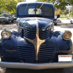
Neither am I. I just swapped in disk brakes on the front and a Jeep rear axle. I've also got a dual 1 barrel intake that I'll install eventually. Right now I'm still finishing the brake and rear end install. Mine is a 46, so I'm guessing period correct is the firewall mounted ignition locked coil. I can see no reason that it would work any better than what you have. If the truck is already set up that way, no reason to change. One thing you should do is get both a service manual and a parts manual. I got both of mine from RockAuto. Just the exploded views in the parts book are invaluable. Enjoy your truck and make it your own. Getting a good running motor, and it looks like the transmission too, is a good thing. Rebuilding one can be upwards of $4000. Plus, you most likely need to pay to ship it somewhere. For some reason, every city doesn't have someone doing this. Boggles the mind.
-
Nobody said you can't. It's just a heads up if he wants everything stock looking.
-
Check your ignition switch...that coil might not be correct. In my 46 the coil is mounted to the firewall, and is locked via high voltage leads from the ignition switch. Not that I think it's required if you just hook things up correctly and ignore the leads from the switch. Just something I noticed. If you still have the coil sticking out of the dash, and it tests OK, might as well keep it stock.
-
1946 WD15 rear end swap...and full replumb of brakes
lostviking replied to lostviking's topic in Mopar Flathead Truck Forum
Baby steps. Today I got the rear wheels back on and set it on the ground. Everything is just for mockup right now. I got the drive shaft connected to the Jeep differential and the angle is about 5-6 degrees. That looks to be the same as the exit angle up front, but I'll check it with an angle finder before I tack the spring perches. Not shown, is that I took the Y block for the rear brake lines off the old axle and swapped it in. I may still use the relatively new 5/16 inch hardline back up to the front. Haven't decided that yet. I know the U-bolts look funky in this shot, but they are nearly vertical right now. I'm a nit picker, so they will be as perfect as I can make them. Same with centering the spring perches on the leafs. Since it's all still "loose" I can fine tune the drive shaft angle if it's not perfect yet. My phone does an angle measurement in the photo app when it detects a long flat surface like the top of the shaft...it thinks it's 5-6 deg. We'll see.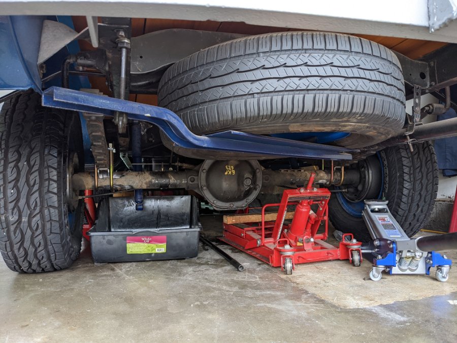

-
1946 WD15 rear end swap...and full replumb of brakes
lostviking replied to lostviking's topic in Mopar Flathead Truck Forum
LOL, I wasn't planning on leaving the jack stands under the frame. The idea was to get the trunk on it's suspension. -
1946 WD15 rear end swap...and full replumb of brakes
lostviking replied to lostviking's topic in Mopar Flathead Truck Forum
Maybe a crazy idea. Should I put the wheels on it and set it on the ground and bounce the bed a few times to help align everything? Just a thought... -
1946 WD15 rear end swap...and full replumb of brakes
lostviking replied to lostviking's topic in Mopar Flathead Truck Forum
Well I guess the stars aligned, because the top plates got delivered a short time ago. On a Sunday! I installed them and let the axle hang from the leafs. I've tried to line them up vertically but they might still need a few more taps from a hammer. Today I just wanted to get the leafs secured by the u-bolts. I did not tighten them to torque, or even that close....just took up any slack. Next I need to get the flange off the rear of the drive shaft and attach the u-joint to the diff. Then I can rotate as necessary to get the angle right. When I'm going that the jack stands will be placed under the axle again to put the weight on the leaf springs. I'll eyeball it with the wheels to try and get the height the same as when it sits on the tires, then check the drive shaft angle. Then we tack weld. That's a job for tomorrow. The washers are a bit larger in diameter than fit to the inner edge of the that angle bend on the top plates also. I'm going to grind each on a bit so that they are able to lay completely flat on the top plates. See you again after the fun tomorrow. P.S. One last note. I'm going to pull some of the leafs, but not immediately.

-
1946 WD15 rear end swap...and full replumb of brakes
lostviking replied to lostviking's topic in Mopar Flathead Truck Forum
Small amount of progress today, while I wait for the leaf top plates that should arrive tomorrow. I went out and got the rear end centered. Its sitting on a couple of jack stands, and I've got my motor cycle lift under the center section. There is a 2x4 under the front where the pinion enters. I can adjust the angle of rotation pretty easy that way. The leaf springs will be able to support the weight of the truck, sitting on the jack stands. Once I get the top plates tomorrow, I'll get the leafs semi secured. I'll leave the u-bolts just loose enough that I can rotate the diff a bit to set the angle. Then, I can tack the spring perches. When they are tacked, I'll remove the rear axle again so I can fully weld them in with some room to work. I still need to replicate some shock mounts, but I have some material that already has the 3 inch semi-circle cut, and some large diameter bolt holes. I've got four of them, so my plan is to put the shock between them and run a bolt through. Tack and move the shock for a full weld. Hopefully all this goes pretty smooth. We'll see.
-
You can put a small block in the current frame, with new mounts. I've toyed with the idea. It can cost around $4000 to rebuild the flathead. Buying a 318-360, the tranny and rebuilding it was thousands less. You need to add up what you would pay for each and decide for yourself which is the better choice. You will never have the power with the flathead, but you will never have the cool once you change it. Hard choice, at least for me.
-
Not sure. I suggest taking a look at the exploded view in your parts book.
-
Dual single carb linkage, planning stage
lostviking replied to lostviking's topic in Mopar Flathead Truck Forum
True, but in the picture above the throttle is being "driven" from the other side. That's where the stock linkage comes in, at least as my memory serves. I haven't looked at that side of the engine in awhile. -
Dual single carb linkage, planning stage
lostviking replied to lostviking's topic in Mopar Flathead Truck Forum
Here is a first attempt. I'll make better mounts for the pivot rod later.
-
Dual single carb linkage, planning stage
lostviking replied to lostviking's topic in Mopar Flathead Truck Forum
I got the Langdon linkage in the mail a couple days ago. Like I thought, a lot of it will be pretty useful to me, just not a bolt on. I used some mounting tabs I had from one of my Harleys and was able to get the main rod mounted with the two rod ends it mounts on. Then the arms and linkage to the carbs. It's all just mock up, but I can open the two carbs by moving the longer arm that goes down to the linkage from the pedal. I'll take a picture, but it's not the end design yet. There is a place online called send cut send dot com. They do laser metal cutting with a pretty decent minimum cost of $29. I'm going to design what I need, the order from them. I'll post the end design and cost information in case anyone is interested later. -
1946 WD15 rear end swap...and full replumb of brakes
lostviking replied to lostviking's topic in Mopar Flathead Truck Forum
Thanks, but I am still using the stock leafs, 1.75 inch. I cut some 1/4 inch plate at work and located the holes on a mill with a DRO and a center drill. Then, since I only have a small amount of time to work there (I am not a machinist, I'm an engineer), I finished the holes at home using my carbide bits and a hand drill. It takes a bit. I won't be using them permanently because I found some online for around $8 plus shipping. I just don't want to wait for delivery...so I'll get the rear end placed and the angle done using these. I'll only tack weld the mounts. The plate I used was part of a full floater kit I've had for a lot of years. I used a band saw to use the sides off with the 3 inch semi-circles. I'll use them to make some new shock mounts and weld them in place on the tube. I'll take some pictures later. Right now it's all talk Some of this has been design on the fly. I didn't measure the old tubes and they were smaller. I was originally planning on using the cast plates that go under the springs and had the shock mount on them. That didn't go well last night, so I've had to adapt. -
1946 WD15 rear end swap...and full replumb of brakes
lostviking replied to lostviking's topic in Mopar Flathead Truck Forum
Where did you pick up those top plates? I'm fabricating some, but I'd rather have a set that have the bent edges. I can radius the edge....but.... -
Don't want to hijack, but what master cylinder and proportioning valve?
-
There are quite a few places to get both new, repop and old parts. bookmarks_9_18_21.html
-
Scarebird disk brake conversion
lostviking replied to lostviking's topic in Mopar Flathead Truck Forum
Search here for double chamber master cylinder and you'll find the thread I found. It was a Toyota and although I haven't put it in yet the OP on that thread says it bolted in with only a shortening of the push rod. -
I used a Jeep Cherokee 8.25 rear. Cheap and easy to find, plus they come in the 3.73 ratio you want. If you get a 1997 and up rear, they have 29 spline rather than 27 spline axles. I've found them using an online search of wrecking yards for $250.

