


Jocko_51_B3B
-
Posts
430 -
Joined
-
Last visited
-
Days Won
3
Content Type
Links Directory
Profiles
Articles
Forums
Downloads
Store
Gallery
Blogs
Events
Everything posted by Jocko_51_B3B
-
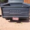
Turn Signals Made in America?
Jocko_51_B3B replied to Jocko_51_B3B's topic in Mopar Flathead Truck Forum
Good to know that LEDs will work too. I don't like the quality of the Dodge reproduction taillights that are available, so I ordered a couple of non-original Grote brand taillights from Amazon. I'll have to change the bulb for 6V. I picked these out because Grote has a good name and because these taillights have 2" mounting studs that will fit the reproduction license plate holders. https://www.grote.com/products/50882-4-steel-two-stud-mount-stoptailturn-lamp-red/ (with license plate window) https://www.grote.com/products/50892-4-steel-two-stud-mount-stoptailturn-lamp-red/ (without license plate window) -
Turn Signals Made in America?
Jocko_51_B3B replied to Jocko_51_B3B's topic in Mopar Flathead Truck Forum
I spoke to Truck-Lite today and the engineer I spoke to was helpful enough to send me several pages of wiring diagrams including how to wire up a Signal Stat 900 for a 6V positive ground system. I'll try to post them when I get a few minutes. According to him, the 900 will work with 6 or 12 Volts, but the indicator light will be a bit dim if not changed to a 6V bulb. The engineer recommended a GE51 bulb or equivalent for a 6V system. The 900 is made in Mexico. The price on Amazon is around $41 which isn't bad if it's a good unit. The reviews are good except for one guy who complained that the 900 won't work with LED lights and another who complained (and I see his point) that his unit did not come with instructions. -
Turn Signals Made in America?
Jocko_51_B3B replied to Jocko_51_B3B's topic in Mopar Flathead Truck Forum
The new Signal Stat 900s look OK. They seem to have good reviews. (Boy I hope they're not from China.) Now I need to find out if they work with a 6V positive ground system. I called Truck-Lite but the guy I spoke to wasn't sure. Waiting for a return phone call. -
I want to mount a turn-signal switch on my steering column. Are any brands made in America? I want to avoid Chinese sourced parts like the plague because I'm tired of wasting my money on junk. I might take a chance on Taiwan though if I can find one.
-
That's better. Thanks. I finally got it (took too long though). The sprocket dot marks are strictly for valve timing. But to set up the distributor ignition timing like the factory did it, the distributor rotor should be at 7 o'clock when #1is at TDC compression. Obviously then a wire will run from 7o'clock to #1 and the rest of the wires will follow around the distributor in order. The sprocket dot marks are NOT adjacent to each other when #1 is in compression, but it doesn't matter.
-
I haven't installed the oil pan yet so I'll just turn the camshaft 1/2 turn and watch the #1 cam lobes until #1 is in compression. Then I'll turn the distributor 180 degrees and that should standardize things for me. I'm not sure why I somehow couldn't get this info out of the B-3 shop manual but if the distributor set-up advice offered by several posters in this forum is the standard, then that's what I'll follow too. Thanks for the help from everyone who posted a response.
-
Dodgeb4ya, thanks for the verification. I'm glad to know that my logic seems to be sound, but a mystery still remains. The only way I can get my distributor rotor at 7 o'clock and #1 in compression at the same time is to remove the timing chain and rotate the camshaft 180 degrees from where I have it now (dots adjacent) and then re-install the chain. But if I do that, then the sprocket dots will not be adjacent which the B-3 book says they should be. (In fact, the cam sprocket dot will be polar opposite to the crank sprocket dot). That's why I'm scratching my head. It's all about those darn dots. When something doesn't quite add up , even if it seems insignificant, I figure I might be doing something wrong. Or at least I don't understand something very well. From page 272 of B-3 shop manual:

-
I have the dots on the sprockets next to each other as the B-3 shop manual shows. That puts the #6 cylinder in firing position, not #1. (#1 is on the exhaust stroke.) With the sprocket dot marks positioned next to each other, I installed my distributor with its rotor in the position shown below. I intend to run a plug wire from the 7 o'clock distributor post to cylinder #6, not #1. If that's wrong I'd like to know why. (The distributor is partly disassembled for cleaning but it is engaged with the oil pump.) Does the rotor position look about right?

-
Can someone tell me if I'm on the right track? The dots on my crank pulley and cam pulley are lined up right next to each other per the shop manual. My #6 piston is at TDC and is in firing position. #1 is in the exhaust position. The distributor rotor is at 7 o'clock. I'm running a plug wire from the 7 o'clock position on the distributor to the #6 cylinder. The rest of the wires will follow clockwise around the distributor posts to the cylinders in the correct firing order. Am I missing anything. Is this pretty much how these flatheads were set up at the Dodge plants?
-
Transmission Reverse Gear Fork and Rail Question
Jocko_51_B3B replied to Jocko_51_B3B's topic in Mopar Flathead Truck Forum
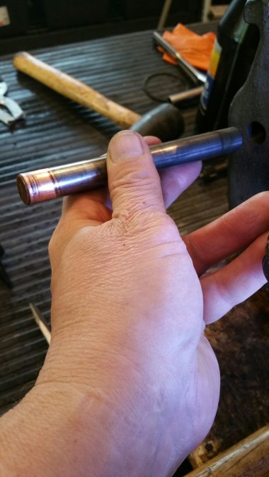
It's brass. I'm not sure if it is a thin layer coat on top of steel or a sold piece brazed on or a brass cap of some kind with a steel core. Nice to know what it is for. -
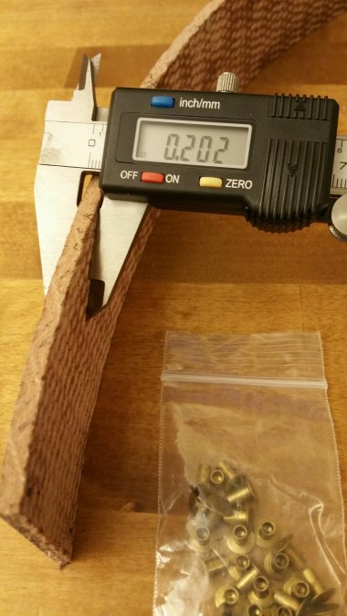
About a year ago I bought an e-brake relining kit (came with the rivets) and now it's time to rivet the lining to the e-brake band. The new lining is about .200 in thick and it looked to me like the old rivets were sitting in counterbores about .100 deep (or about half-way into the old lining). Anyway, my first thought was to bend the lining into the band, mark the lining with a fine tip marker through the band holes to locate the rivets, then remove the lining from the band and drill .001 counterbored holes where the rivet heads will go. But before I bend the new lining to fit it into the band, I thought I better find out if anyone on the forum has done this before. My question is whether there is something that should be done to the lining to make it more pliable (like soaking it in water overnight or something like that) before bending it and possible breaking it or is it OK to just go ahead and fit in into the band. After I get the lining positioned correctly in the band, I plan to try using a pin punch and transfer punch to sink the rivets.

- 7 replies
-
- 1
-

-
- brake lining
- e-brake lining
- (and 3 more)
-
I disassembled a 1950 4-speed trans just for kicks and to clean it up and check it for wear and possible bad bearings. I'm putting it back together now and I noticed that the reverse gear fork rail has one end made of brass. I'm just wondering why that might be and whether it makes a difference in which way it should be re-installed - brass or steel end first. I didn't pay enough attention during reassembly, but I think the steel end gets inserted first which puts the brass end at the rear of the trans. The shop manual doesn't say except it does say that the rail should be installed from the rear.

-
B3B Bed Hardware Question
Jocko_51_B3B replied to Jocko_51_B3B's topic in Mopar Flathead Truck Forum
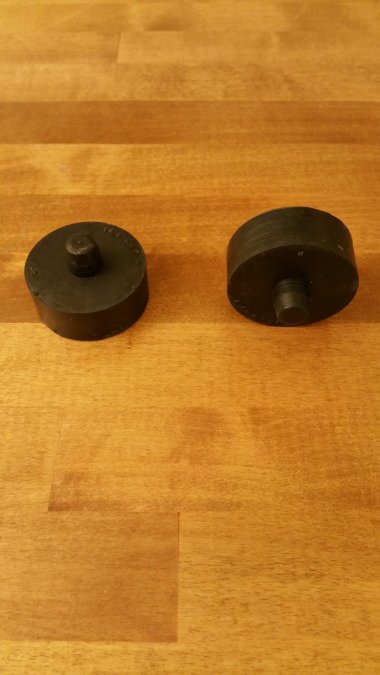
Here's a photo of the correct-type bed crossmember isolators I got from Horkey's. Again, the two round ones fit under crossmember 3. It takes two of the rectangular isolators stacked one on top of the other to equal the thickness of a round rubber isolator. So, a total of twelve rectangular isolators are needed to isolate crossmembers 1,2, and 4 from the frame.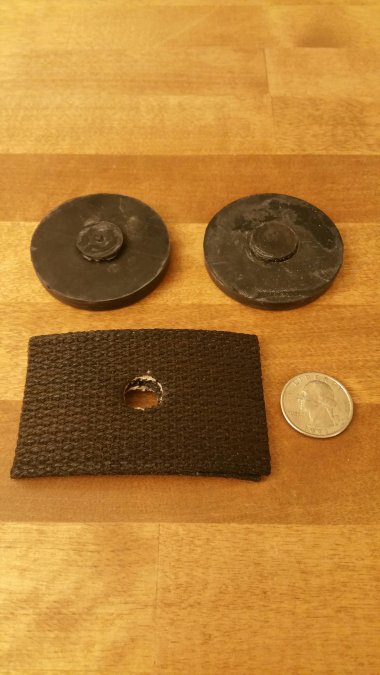
-
B3B Bed Hardware Question
Jocko_51_B3B replied to Jocko_51_B3B's topic in Mopar Flathead Truck Forum
Yes, but they sent me the correct rubber pads (1/4 in thick) and twelve waterproof cotton isolators (more than enough) free of charge along with free overnight shipping. They realized their error and more than made up for it. Going the extra mile to make things right is not too common these days. I'd definitely do business with Horkey's again. -
B3B Bed Hardware Question
Jocko_51_B3B replied to Jocko_51_B3B's topic in Mopar Flathead Truck Forum
I finally have some good information after talking to Bruce Horkey directly. The Pilothouse series was designed with four steel crossmembers supporting the wood planks which are 3/4 in thick. Front to rear (I call them # 1 to #4), the first three crossmembers are 48 5/8 in. long and the rearmost crossmember (closest to the tailgate) is only 40 1/8 in. long. The first two crossmember are bolted to the frame using bolts that fit through large 3 in. diameter washers. Crossmember number three is kind of odd because it is a floater. It does not bolt to the frame. The only bolts that hold it in place are the bolts that pass through the skid strip holes directly above it. The rearmost crossmember also bolts to the frame using the same bolts and large 3 in. washers as crossmembers #1 and # 2. Dodge realized that it had to cushion the four crossmember from riding directly on the frame so crossmember #1, #2, and #4 were cushioned by 1/4 in. thick square-shaped insulators made of some kind of waterproof material. Crossmember #3 was supported by two 1/4 in. thick round rubber insulators which were not bolted to anything. Instead, the #3 rubber insulators are held in place by nubs molded onto one side that are inserted either into holes in the crossmember (nubs up) or the holes in the frame (nubs down). Either way is OK since there is no way for them to fall out because the nubs hold the rubber insulators firmly in place. The rubber insulators I posted in my original post are incorrect. At 3/4 in, they are too thick. Horkey is sending me the correct 1/4 in. thick rubber ones along with six 1/4 in. thick waterproof cotton insulators for the other three crossmembers. Horkey's stocks all the parts for Pilothouse beds and has been very responsive and easy to work with. -
B3B Bed Hardware Question
Jocko_51_B3B replied to Jocko_51_B3B's topic in Mopar Flathead Truck Forum
That's what I don't understand. Your link photos show much thinner isolator pads not to mention the fact that Horkey only sent two isolators, not eight which is what I would expect for four crossmember. So I'll get back to Horkey again. I'll post an explanation once I have some better information. -
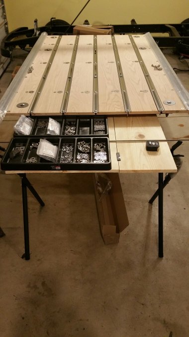
I'm starting to lay out the boards for the bed and to inventory the hardware I bought from Horkey's. But along with the boards came a couple of black rubber "cushions" that I can't figure out. I spoke to Horkey directly, but I still can't understand where they go. I'm told they fit under the third steel crossmember (the one that isn't bolted to the frame), but if I place them there, they will raise the third crossmember 3/4 of and inch higher off the frame than the other three crossmember. That doesn't make sense to me. Anyone have a clue?
-
B3B Transmission Cover Plate
Jocko_51_B3B replied to Jocko_51_B3B's topic in Mopar Flathead Truck Forum
Brent, Your photos are a good reference in case a good B3B transmission cover plate comes up for sale on eBay. It would be interesting to find out how many transmission cover plate variations are out there and to which year and model Pilothouse trucks they belong. Glenn -
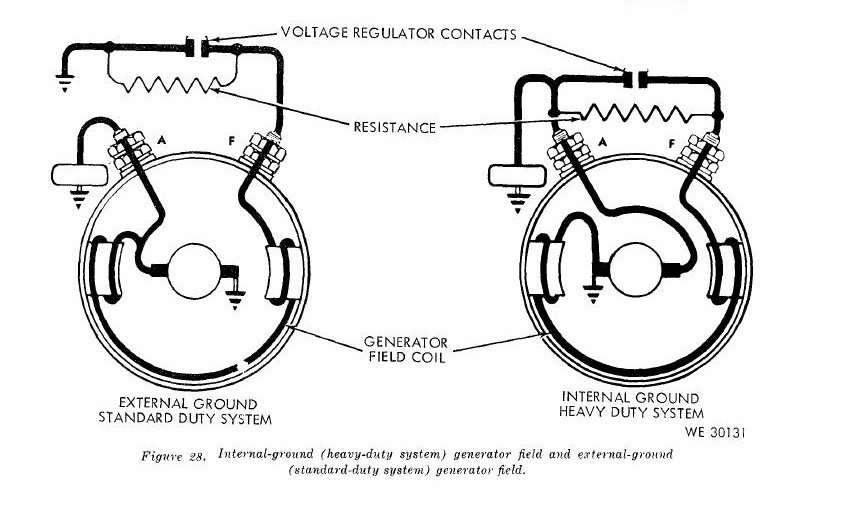
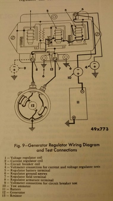
Difference Between Externally Grounded and Internally Grounded Generators Generators are classified as Type A or Type B. For Type A generators, the field current (and thus the output voltage) is controlled by rapidly vibrating (opening and closing) voltage regulator contacts inside the voltage regulator. These vibrating contacts provide intermittent grounding for the field windings. Because these contacts provide ground for the field windings from outside the generator itself, this type of generator is called an external ground (Type-A) generator. For Type-B generators, the field current is also provided by rapidly vibrating contacts inside the voltage regulator, but in this case, these contacts do not provide ground. Instead, they sample the generator output. The field windings are grounded inside the generator so this type of generator is referred to as an internal ground (Type-B) generator. Type A - External Ground Type B - Internal Ground The diagram below comes from the 1951 Dodge Truck Shop Manual on page 208. The generator ( labeled #12) in the diagram matches Circuit A above. So, the generators in Pilothouse Trucks are Externally Grounded. How to Polarize a Pilothouse Generator To polarize an "A" circuit generator (external ground), momentarily connect a jumper lead between the regulator BATTERY and ARMATURE terminals after all leads have been connected, but before the engine is started. (This is how a Pilothouse Generator should be polarized!) To polarize an "B" circuit generator (internal ground), disconnect the lead from the regulator FIELD terminal, and momentarily touch the lead to the regulator BATTERY terminal. This should be done after all other leads have been connected and before the engine is started. (Pilothouse Trucks are not polarized this way!) A Goes With A and B Goes With B Another thing to remember is that generators AND voltage regulators are classified as either Type-A or Type-B. They must match. If you have a Type-A generator, then you must use a Type-A regulator. Type-B regulators are only for Type-B generators also. A Way to Check Whether a Generator is Type-A or Type-B... I wanted to prove for my own satisfaction that my B3B generator is externally grounded (Type-A). So, using the Type A and Type B diagrams above as guides, I measured the resistance between terminals A and F and compared it to the resistance measured between F and ground (which I call G) on the generator case. Here's how I decided if my generator is Type-A or Type-B: If the generator is externally grounded (Type A), then the resistance measured between terminals A and F should be less than the resistance from F to ground (the generator case). If the generator is internally grounded (Type B), then the resistance measured between terminals A and F should be greater than the resistance from F to ground (the generator case). Why should this test work? Because for Circuit A (External Ground) the ohmmeter current from A to F only goes through the field windings, whereas current from F to G goes through the field windings AND the armature windings. The reverse is true for Type-B). For my generator, (A to F) was 3.6 Ohms and (F to G) was 3.9 Ohms which tells me that my generator is externally grounded which agrees with the diagram from the Dodge shop manual. (Information above was taken from http://www.bowersflybaby.com/tech/delco_remy_generator.pdf and the Dodge B-3 Shop Manual.)
-
B3B Transmission Cover Plate
Jocko_51_B3B replied to Jocko_51_B3B's topic in Mopar Flathead Truck Forum
When I bought my B3B both toe boards were missing but I saw a toe board set for a 1950 B2B for sale on ebay and I bought the set. The lower toe board came with the pedal studs attached. The transmission cover is also from a 1950 and it lacked the pedal studs. I guess Dodge moved the studs from the toe board to the trans cover plate in 1951. If anyone has a B3B, it would be interesting to know where the pedal studs are located - toe board or trans cover. In any case, I think my trans cover and toe boards will work out since they are both from a B2B. -
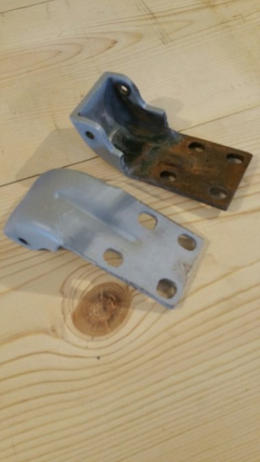
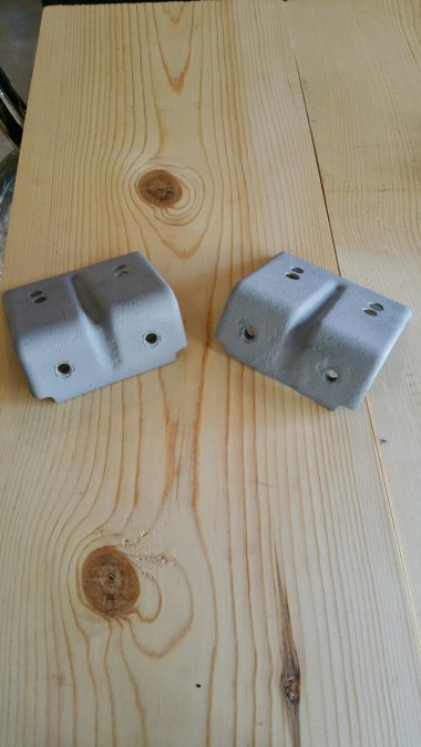
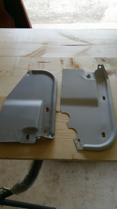
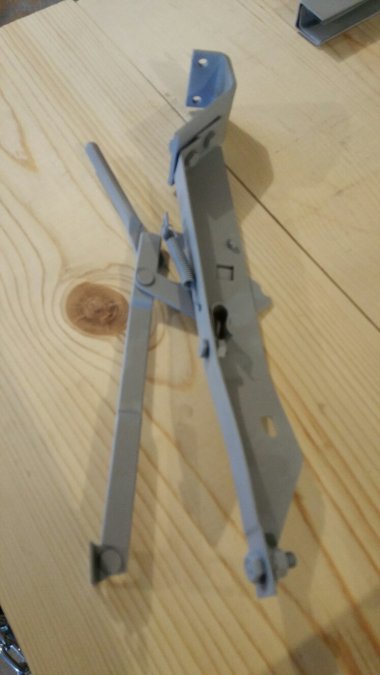
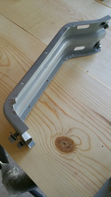
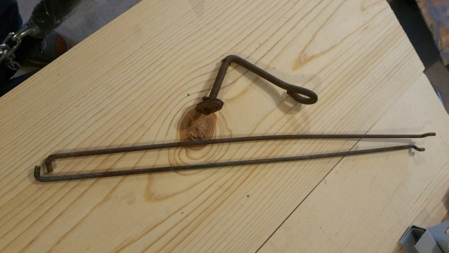
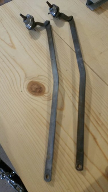
I'll probably leave the windshield wiper links and seat handle / rods go unpainted with most of the rest of the parts black. Since Don Bunn's book says that the seat riser and frame should be cab color, I'll probably paint the seat brackets and seat regulators cab color too but it seems unusual that Dodge would have painting those small parts to match the cab instead of just painting them all black like they did for the bed. I'll paint the door hinges, battery box, and fender brackets to match the cab. Bunn's book lists the splash shields as black so I'll do the support shields and extensions in black too.
-
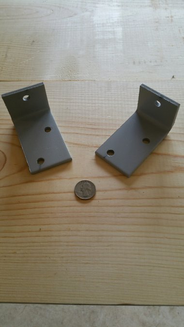
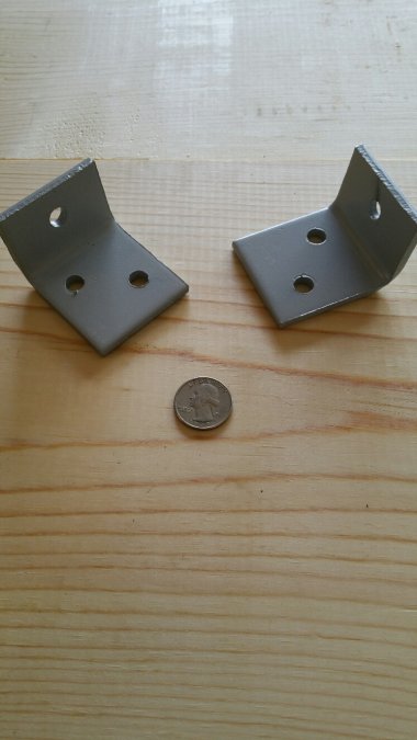
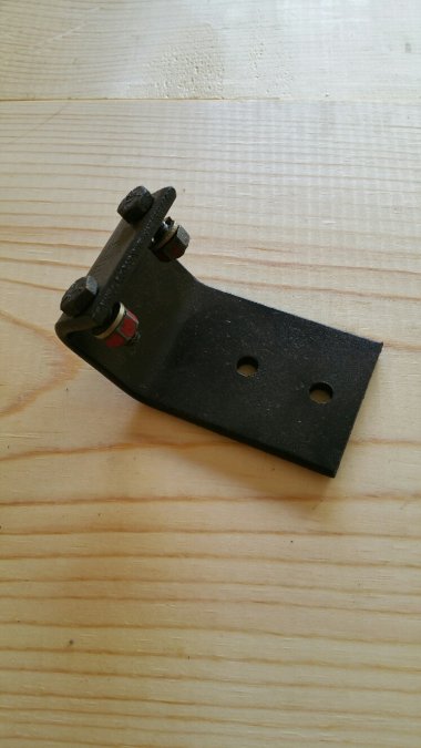
My B3B sheet metal painting began last week. Cab color will be dark green, bed black. But I also want to be mostly correct about the colors of the more hidden, smaller, and obscure parts. I think most of these parts should be black or unpainted, but I want to check with other Pilothouse owners about the colors they believe to be correct. Here's a list of the parts in question. If you are pretty sure of the color of a given part, please share your knowledge. (Don Bunn's book has a lot of good part color info on page 32, but most of the parts I listed below are not covered in Don's book as far as I can tell.) I posted photos of each part at the bottom of this list to make it easier to see which parts I'm talking about. Number Dodge Part Name Dodge Part Number Dodge "Part List" Page Number My Best Guess 1. Upper Door Hinges Cab Color 2. Lower Front Fender Brackets 12-05-15 12-1 Black 3. Upper Front Fender Brackets 12-06-3 12-1 Black 4. Support Shield 12-04-38 12-1 Black 5. Extension 12-04-36 12-2 Black 6. Catch 15-15-1 12-1 Black 7. Splashshield 12-04-4 12-1 Black According to Bunn 8. Cowl Lid Hinge 23-61-65 23-14 Black or Unpainted 9. Cowl Lid Brace 23-61-31 23-14 Black or Unpainted 10. Battery Box Black or Cab Color 11. Window Channels 23-09-50 33-12 Black 12. Seat Brackets (L-Shaped) none 23-14 Black or Cab Color 13. Seat Regulators 23-47-6 23-14 Black or Cab Color 14. Horn Bracket Cab Color According to Bunn 15. Steering Column Support Bracket Black According to Bunn 16. Seat Handle 23-47-55 23-14 Unpainted 17. Seat Rod 23-47-66 23-14 Unpainted 18. Windshield Wiper Links 23 -67-79 23-16 Unpainted 8. Cowl Lid Hinge 7. Splashshield 6. Catches 5. Extensions 4. Support Shields 3. Upper Fender Brackets 2. Lower Fender Brackets 1. Upper Door Hinges 9. Cowl Lid Brace 10. Battery Box 11. Window Channels 12. Seat Brackets - Front 12. Seat Brackets - Rear 13. Seat Regulators 14. Horn Bracket 15. Steering Column Support Bracket 16. and 17. Seat Handle and Rods 18. Windshield Wiper Links


-
jmoonier, You have a great attitude. I'm approaching my restoration with the same spirit of learning and adventure. I've never had to rebuild an engine either so I took a course at a local community college just so I could wear out the instructors with all kinds of basic questions. Whatever I turn my attention to on my '51, I learn something new - from welding to brake lines to engine work to paint. At the same time, I'm finding that just learning about the history of these Pilothouse trucks is fascinating. We don't see that many of them compared to Fords and Chevy's which makes them all the better! Glenn
-
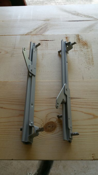
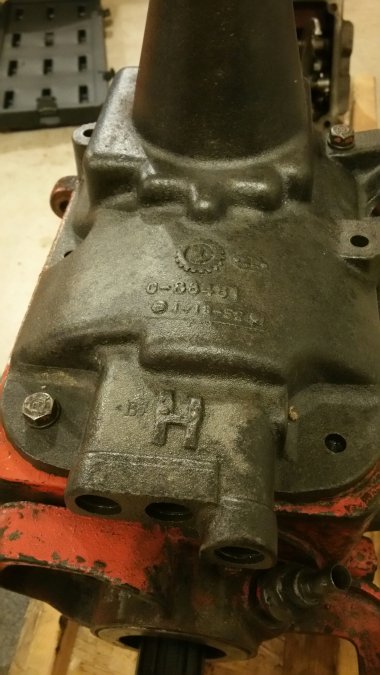
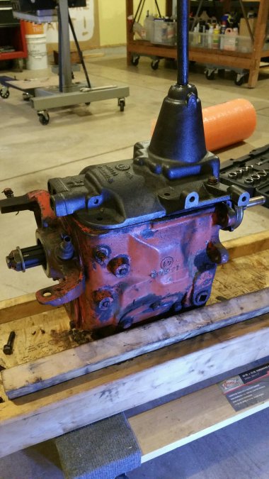
Jay, I had a 1950 B2B and I presently own a 1951 B3B. They both had exactly the same 4-speed transmission. Here's what both transmissions look like in case you decide to go with a four speed. I don't know if these trucks could be ordered with a 3-speed, but if it works and drives OK and you're happy, then why change? By the way, I'm getting ready to paint my '51. Did you use base/clear or single stage? I'm still trying to decide what to use.


-
The B-3 Series shop manual shows a picture of the dots on the crankshaft and cam pulleys right next to each other so I decided to follow the book's example. That put my #1 and #6 pistons at TDC. (#1 and #6 are companion cylinders.) From looking at the cam lobes, #6 is in firing position. (#1, which is not in firing position, is almost ready for the intake valve to open.) I installed the oil pump and distributor so that the rotor on my distributor is at 7 o'clock. So, when I install my plug wires I'll just run a wire from the 7 o'clock distributor post to the #6 plug. Then I'll install the remaining plug wires in accordance with the firing order. That should work. My B-3 shop manual doesn't seem to say anything about making sure that the rotor is in the 7 o'clock position. As long as the the rotor lines up with the wire going to the cylinder that is firing does it matter? It would be fun to know exactly how the Dodge factory ran the wires from which distributor post to which cylinder. I haven't seen a good photo of that yet. If anyone has that info, please share it.
