


Matt Wilson
-
Posts
641 -
Joined
-
Last visited
-
Days Won
2
Content Type
Links Directory
Profiles
Articles
Forums
Downloads
Store
Gallery
Blogs
Events
Everything posted by Matt Wilson
-
Deleted for accidental double-post.
-
Thanks to you all for the replies so far. You guys are giving me ideas for other ways to mount things, so that's good. I still really have a preference to have studs that will protrude far enough above the head nut that I can add things later without having to remove the nuts (or bolts if I end up using bolts) to put something underneath, but I may not be able to go that route. I may have to decide up front all the things that I'm going to want up there and mount them all under the nuts. I would just prefer the flexibility of doing it the other way. I called Milodon this afternoon and their studs have 1" of thread at each end, like ARP, but it seems that they are more expensive than ARP. Having said all the above, I do have a set of studs I bought from Vintage Power Wagons that would barely do what I want to do, but I'd have to use a somewhat thin nut for the head nut (27/64, which is 0.42" tall, so not as tall as the 0.5" tall nut that ARP and Milodon recommend), omit the flat washer under the nut, use an extra-thin nut to hold the accessory in place, and no lock washer under that accessory nut....and then I'd have a couple of threads protruding above it all. Also, the VPW studs don't have as much thread length available to go into the block (0.72" vs. 1" for the other brands). Can anyone tell me how tall the factory nuts are (when studs are used)? Another question: Are the studs supposed to be threaded all the way into the block until the shank is against the block? The reason I ask is because one of the ARP reps I spoke to said I should not do that and should instead leave the stud protruding about half to one full thread above the deck. He said that if I run it all the way down, I run the risk of pulling the threads out of the block when torquing the nuts. On the other hand, the Milodon website states the following. So who's correct?
-
Well, if it's not too much trouble, then that's fine, but if you can't find it easily, then maybe I can call Milodon and see if they can spec anything by size.
-
Do you happen to have the part number, or do you know if Milodon lists them by size? I called Pioneer and they only have them by application, and no listing by size, so that was a dead end for me.
-
Ok, I understand better now, thanks!
-
Thanks, Marty. I don't quite visualize every detail of your setup, but I get the basic idea, I think. I still think there's barely enough room for the head nut, a bracket and another nut and a possibly a washer under that second nut, when the upper threaded end of the stud is only 1".
-
For those of you running head studs, how do you manage to connect accessories (such as horn), throttle linkage, etc., on your studs? The reason I ask is because ARP studs (which is what most people seem to be using) have threaded sections that are only 1" long, according to two different ARP reps I've spoken to. That makes it difficult to install nuts for holding the head in place and then having enough thread length remaining above the nuts to install accessories and such. I think I might be able to find a combination of nut thickness, washer thickness, etc., so that I'll have enough thread to do this, but it'll be awfully close, and if the studs turn at all during nut installation, then it may mess up the whole spacing of everything. The biggest reason I really want to use studs is because I'm going to install dual carbs and having an array of studs will make it easier to figure out throttle linkage mounting arrangements after assembling the engine and installing in the vehicle. Also, one never knows when I might want to add an accessory at some point in the future, such as power steering or air conditioning....or who knows what. I suppose another question is whether the threaded sections of the ARP studs are actually a bit longer than 1". If they were just a little longer (even 1/16 or 1/8" ), then that would make a big difference. Probably wishful thinking, but if they were nominally 1" long, but in actuality a little longer, it would be helpful to know that. I wonder if someone can tell me if this is the case?
-
Just one piece of data here, for whatever it's worth. One factor in my decision to pull the 230 out of my Power Wagon (though a small factor compared to the metal shavings I discovered coming from the tappet bores, which I discussed on your other thread) was that the valve guides were worn. I had paid the machine shop to replace all guides, but I'm 99% certain they didn't, since I later found that there was 2 - 4 times the allowed valve-to-guide clearance per the manual in most or all of them. I had somehow overlooked this when assembling the engine. The valves were new, so I knew it was an issue with the guides. I'm pretty certain I've also read about other people with guide wear on these engines. My guides were completely unmodified, just FYI. The point of this is that guides in these engines do wear, despite there being no side loads and despite the low-rpm operation, etc., so cutting down the length may accelerate that. Having said all this, my engine ran well when I decided to pull it, but who knows how long it would have stayed that way. Cutting the guides may produce other issues, such as allowing oil to get sucked into the combustion chambers more easily. My combustion chambers were somewhat of an oily mess, so some of that may have been taking place. Though it's not 100% solid data for your decision, I think it's worth considering.
-
Thanks. I'll do a little more cleaning on it and have a better look to see if there's a way to push and turn it to release it or not. If not, then I'll just have to do like White Spyder suggested and soak the heck out of it and rinse it really well. I've got engine cleaning brushes in a variety of sizes, so I'll be running those up through the oil passages too.
-
As others have indicated, I think my filter setup is different from yours, but I may end up soaking it in solvent and thoroughly rinsing it, as you suggested, if I can't find a way to disassemble it.
-
The tappets I put in my 230 were probably new (NOS) at the time, and I think I can put my hands (and micrometer) on them when I get back in town at the end of this week. I'll try to remember to do that. I expect they will be somewhere in the range of 0.6235 - 0.6240, as that's what the manuals all state they should be for new parts. I can tell you by memory that all the unused oversize tappets I've measured (several dozen of them) were right in the range where they were supposed to be for new parts, and I seem to recall that most of them were at or very near the bottom of that range. So your measurements for your tappets (0.6235) sound just right for standard size tappets, although at the very bottom of the range. It sounds like they have very little wear.
-
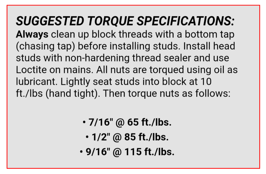
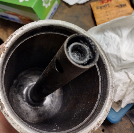
Does anyone know if the full-flow filter housing can be disassembled? This unit is new to me and pretty gunky, so I'd like to take it apart and clean it, if that's possible. In particular, I'd like to clean the spring-loaded valve in the tip of the stem, and it will be easier to give it a good clean if I can take it out of the stem. I tried sticking a screw driver sideways through the holes near the tip of the stem and tried to unscrew the stem, but it seems like it doesn't unscrew (not surprising) but I didn't try very hard for fear of messing up something. Any other way to take the valve and spring out? Thanks.
-
I ordered the valve guide driver in the photo below, many years ago, to drive out the guides in my 230 flathead six. Ordered it from Goodson, as you can see (part number GP-524-G). It worked just fine when used with a big freakin' hammer. I seem to recall having to smack it pretty hard, but it wasn't a big deal. I had my engine on a stand that supported it only at the back, and I was concerned about hammering so hard with the front of the engine unsupported, so I grabbed a 4x4 or 6x6 piece of wood that I had laying around and used that to prop the front end up. Worked well and I don't think it was expensive - something like $10 around 10 years ago.

-
Napa part numbers VG419 and VG420 are the guides, and Napa's website says their OD is 16.695 mm, which converts to 0.6573" for both part numbers. I have several used ones that came from the 251 that I'm coverting to a 265, and those measured between 0.6568 and 0.6570.
-
No problem. Hopefully there is some insight somewhere in there. As for the rings around those few tappets of yours, I don't know if I would worry about that. I think the barrel section of the tappet can tolerate some damage here and there, as long as it's relatively small in area compared to the overall size of the barrel, and as long as there is no raised material to cause damage to the bore. The condition of the bottom end where it contacts the cam lobe, and the diameter of the barrel (since that affects clearance within the bore) are the most critical things. Also, the condition of the adjuster screw, where it contacts the valve tip is important, meaning you don't want it be dished out from wear. I would get the tappet cam contact surface re-worked and have the adjuster tip refaced too. I'm sure there are shops out there who CAN and WILL do a good job on tappet bores, without needing special equipment. I've read about them, but they are apparently hard to find, even in the large metroplex of Dallas-Fort Worth, where I live. I think I could probably convince the one machinist who gave me encouragement to do the reaming myself to do it if I tried a little harder. I think he is just busy and it's a little bit of an unusual type of job for him, so he was hesitant. I may try to go to him again and see if he'll do it, but we'll see... I've never tried to buy the 0.001 oversized tappets, but I suppose they are out there. I found the 0.030" oversize tappets to be hard to find, but I found them at AMS Obsolete in Georgia. They were pricey, but I was grateful to find them. You might give them a try for the 0.001 parts. You could also try Vintage Power Wagons, Andy Bernbaum, Midwest Military in MN (John Bizal). One thing I should note that is that when I've bought replacement tappets, especially the oversize ones, several of them have had rust on them. In some cases, it was enough that they were unusable and unrepairable, so I called the supplier to get replacements, but they instead credited me for those, saying the rest of their stock were probably not any better. They were obviously not going to take the time to inspect them closely enough to find the ones that had no rust. Replacements I found elsewhere sometimes had some rust as well, even though I specifically asked for ones without rust. Some of the 0.030 oversized parts have some rust. If the rust is minimal in area and is confined to the barrel section, then I give it a little localized polishing and I don't worry about it any further, but if there's any at all on the cam contact surface, as is the case in several of the 0.030 oversize parts, then I won't use it as is. If it looks like it's just very, very shallow surface rust, then I might try giving it a slight polish (just a few swipes with some 320-grit paper as suggested by one long-time cam grinder). If the cam contact surface has anything deeper than that, then I consider it no good and I will send those tappets off for resurfacing. I could try to ask the supplier to replace them, but I have no confidence that what I would get would be any better, as it would require the supplier to remove ALL the cosmoline and examine each tappet VERY closely under some level of magnification to be sure there is absolutely NO rust. That's very tedious and if they miss even a small spot, I'll still have to do something about it, so it's just not worth it to them to take that kind of time. It's not ideal, but I don't think I can fault them for that. I just have to be ready to send those tappets off for refacing and I figure it's a part of dealing with the situation. Others may see it differently, but in my view, most suppliers are simply not going to take that kind of time, especially if there's a good chance they'll miss something anyway. I just started following your engine disassembly thread last night and I'll keep an eye on it periodically. I'll be interested to see how your tappet situation pans out. Good luck!
-
Full Flow Oil Filter Part Number and Applications
Matt Wilson replied to Matt Wilson's topic in P15-D24 Forum
Good to know about being MCH instead of MCL. The MCH 6103 has the return spring on the lever pivot, as you pointed out, and my Power Wagon starter also has a return spring on that pivot. However, your pivot mount is offset pretty far to one side, while mine is offset only a little and has the spring on the opposite side from where your starter's spring is located (see photo). The MCH 6106 does not have a spring and its lever pivot is centered between two lugs (a clevis) that are centered at the switch. I wonder why some starters were deemed to need a return spring and the others not, even in the same application. My foot pedal/button in the cab has a big return spring that the pedal travels through, so it seems like that would pull the lever back and make the pivot spring unnecessary. My starter lever splits into a clevis at the top, where the foot button attaches (see second photo). Both of the MCH levers don't end in a clevis. I wonder if the foot button has a clevis instead. Based on the amount of offset in the "dogleg" of the lever from my starter (2nd photo) vs. the MCH units, I think the lever from mine would need to be swapped onto yours. I wonder how difficult that would be. Does it look like the levers on your starters are easily removed? Or I could possibly make a lever if I had to. Thanks so much for the info.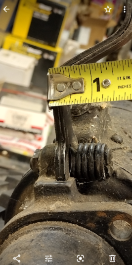

-
I'm going to try to go through my saga (which is ongoing) and see if that offers any direction for you. Here goes..... I had a 230 engine in my '49 Power Wagon. I rebuilt the 230 about 19 years ago. Tried to do everything as correctly as I possibly could, being very picky,referring to the manual for everything (actually three different manuals I had at the time and occasionally a fourth), getting stuff redone when it was not done correctly the first time, etc. That is, except for one area - the tappets and their bores. I measured the clearances the way Sniper's manual excerpt describes. In fact, I have a manual that shows the same procedure, except that its stated wear limit is 0.0015" clearance instead of 0.002" (the stated new part clearance is 0.0000 - 0.001", which is smaller than I expected, honestly, and obviously, you don't actually want zero clearance, but I guess they had to give a range). That manual is Army manual TM 9-1840A/TO 19-75B-15, which is for the Dodge M-37 (military truck, in case you're not familiar). It uses the same engine as my Power Wagon, with minor differences, and same engine as most any other light truck or passenger car. When I measured the clearances, they all came back significantly beyond the wear limit, with some being 3 - 4 times that. Being somewhat inexperienced, I didn't know what to do about this, and I was probably exhausted from the whole process of the rebuild, as there were many issues along the way (another story). I think I knew that oversize tappets were available (because that manual talks about this), but I seem to recall talking to several machine shops and they didn't have the tooling to oversize the bores, and I do recall very clearly that they all said this amount of clearance would be fine, saying this clearance is not that critical. So having gotten expert input, I went ahead with the situation as I just described. I reassembled the engine, installed it, and it ran well for several thousand miles (probably in the neighborhood of 8,000 miles, but it's hard to say for sure because the odometer didn't work - but it was my daily driver for over a year and I knew how many miles all my routes were, and my routine was pretty consistent). One day, I took the valve/tappet covers off to look in there and noticed four or five of the tappets had streams of oil full of metallic shavings flowing from the bores. Beautiful, glitter-filled oil, but very alarming. My mind immediately thought of the large clearances, but to this day, I don't really know if that's what caused the metal shavings or not. I also remembered an early valve adjustment session when I noticed that a few of the tappets weren't rotating, or at least not consistently like most of them. So I wondered if that could have contributed to the glittery oil. Mostly, I blamed the excessive clearances, but in any case, I couldn't continue to run the engine like that, so I pulled it with the intention of repairing it, but it sat mounted on my stand for several years while I licked my wounds and focused on other things happening in life and tried to get motivated again. Fast-forward several years and I finally had time and took interest in the truck again and decided I would install a 25" engine, then made up my mind it would be a 265. As I was planning that build, I swore that I would do whatever was needed to achieve proper tappet-to-bore clearances (along with everything else being correct). When I performed the clearance checks, most or all of them were beyond the 0.0015" wear limit stated in the manual I mentioned above. Several had 2 - 3 times the allowed wear limit clearance. I bought 0.008" oversize tappets, which are available from several sources, and took them and the block to a machinist to rework the bores so they would have 0.001" or slightly less clearance with the tappets. When I got them back, I found the clearances were now beyond wear limits compared to the 0.008" oversized tappets. The machinist had screwed up. Perhaps I should have taken everything back to the machinist and demand he make it right, but based on comments he made relating to other work I had done at the time, I had no confidence he would be willing to do that. Also, if he screwed this up this time, why should I expect him to get things right the next time. Instead, I began figuring out my next move. I considered having the tappets plated to take up the excess clearance, but there were issues with that approach. I also considered opening the bores to accommodate press-fit bushings that would then be honed to fit the oversized tappets, but that's when I found some 0.030" oversize tappets. I spoke to several machine shops and they all expressed a lack of interest or equipment for doing the job (a lot of them seem to think they need a specialized CNC setup with custom fixturing, like they use for their high-end racing V8 tappet bore work, but I'm not convinced that's what's needed if you can find someone who's willing to just take the time to set up their mill for this job). However, one shop gave me some guidance and some encouragement to do it myself (of course, it begs the question....why wouldn't he do it, if he's so confident I could do it?). Anyway, armed with that, I set out to gather the tooling I need to do the job myself. With the guidance I received from the machinist and from a local tooling shop, I bought a standard chucking reamer to open up the bores part-way and a custom piloted reamer to open them the remaining amount so that I would get right at 0.001" clearance. I have those tools now and will hopefully get to that job in the next several weeks. I'm nervous, because I'm not really set up to do that kind of work, but the machinist and the tool company thought I could do it. I do have my old 230 block that I plan to practice on first, so that should give me some foreknowledge of how it will go on my "real" engine (the 265). In the end, I may chicken out and try again to find a shop to do it for me using my reamers. So what is all of this telling you? You can take what you can glean from it, but I think one thing it says is that it might be easier said than done to find someone who is willing and is competent to do this kind of work. Some shops will advertise that they do this type of work, but when you talk to them, they'll say they can't do our engines because they only have fixturing for a limited range of engines. Honestly, I don't think special fixturing is required. If you lay the block upside-down on a milling machine and perhaps shim it as necessary to align the milling head with the tappet bores (you can't assume that the bores are exactly perpendicular to the block deck due to normal factory machining errors), I think you (your machinist) should be able to do this job. If the bores are not very far off, the mill could be used to make them perpendicular to the deck, although actually, the preference is probably to make them perpendicular to the camshaft bearing bores if that's possible. In any case, I doubt the bore alignment is off by enough to matter for most of us. The point of all this is that I think a machinist who cares and has a large enough milling machine can do a perfectly good job of oversizing the bores. i think my story also says that if your clearances are only slightly out of sorts (say right at the wear limit or a few ten-thousandths beyond), then maybe it's worth keeping things as they are, or perhaps finding some of the 0.001" oversize tappets that some manuals talk about. Those might be just enough to bring clearances right back where they should be, although be aware that your bores are no longer perfectly circular, so oversized tappets might be a little tight in the fore-and-aft direction, since that's the direction of least bore wear. A point for measuring bores is to consider using plug gages. I tried endlessly to use telescoping (snap) gages and outside micrometers, and I think I got fairly accurate answers, but when double-checking my measurements, I would occasionally get a number way out in left field. Those gages are tough to use. There are probably other measurement tools I could have bought, but even those sounded difficult to use. I finally discovered plug gages at McMaster-Carr, which come in 0.0005" increments. Those are best used for holes that are close to circular, like mine, and the more out of round they are, the larger the error. I bring it up only as a consideration. Another point is that I rarely hear anyone else talk about having issues with this area of the engine, and it seems that people frequently ignore these clearances during rebuilds, so unless you have truly excessive clearances, or damage to the bores or tappets, it may not be a big concern. A couple of my manuals even mention that tappets rarely need replacement since they are constantly bathed or sprayed with oil. Another piece of info...different repair manuals call out different clearance specs, so that adds to the confusion over what's acceptable. The M-37 manual I mentioned above calls for a new-part clearance of 0.0000 - 0.001 and a wear limit of 0.0015. Another manual (TM 9-808, which is a WWII Dodge 3/4-ton truck manual) calls for new-part clearance of 0.0000 - 0.0007 (yes, seven ten-thousandths), and a wear limit of 0.0025 in terms of tappet stem diameter wear, with no mention of bore wear. Another manual, D-12154, which covers Chrysler Six Cylinder Industrial Engines, calls for a new-part clearance of 0.0000 - 0.001 and wear limit clearance of 0.0015, like the first manual I mentioned. Then there is Sniper's manual that seems to indicate a wear limit of 0.002". Finally, you asked in a separate post about whether the tappets have a crown where they contact the cam. To my knowledge, all of the Chrysler/Dodge/Plymouth/DeSoto flathead six tappets do have a crown. It's not obvious to the naked eye, but if you hold a tappet up to a straight edge, or better yet, if you hold two of them with their cam contact faces against each other, you'll see that those faces do not sit flat on each other. If you re-use your existing tappets, you should get them resurfaced by a cam grinder. Many of them (probably most or all of them) offer this service. Hopefully this is of some help, even though it may be hard to decide what the takeways are. Let me know if you have questions.
-
Full Flow Oil Filter Part Number and Applications
Matt Wilson replied to Matt Wilson's topic in P15-D24 Forum
Ah, wow! I'll certainly be interested to hear what you find. Not sure if you mean that it will be for my info (another p/n to add to my list), or if you mean you would be willing to sell to me. Either way, it could be useful. I hadn't really started trying any other sources yet, including an ad on this site, but was going to pretty soon. When you look, please see if it's a high-mounted starter too. Thanks! -
Full Flow Oil Filter Part Number and Applications
Matt Wilson replied to Matt Wilson's topic in P15-D24 Forum
No worries, don't spend any more time. I appreciate all the help you've provided so far. I had thought about placing an ad here, but haven't done it yet. I did look on eBay. I'll look for wrecking yards in my area that have old cars, although I don't think there are many. The upside to finding one in a wrecking yard is that I could go measure the parts before purchasing. Of course, there are also old car parts suppliers, some of which are wrecking yards, and maybe I will, now that I have some part numbers to try. Maybe they'd even be willing to take measurements for me. -
Full Flow Oil Filter Part Number and Applications
Matt Wilson replied to Matt Wilson's topic in P15-D24 Forum
Yet another update... I called one of the very few places that advertises the 1821 and 1825 starters (Filter Products Corporation), and they told me the 1825 is not in stock and the only 1821 in their system is in Winnipeg, Canada. It's not worth it for me to pay the price of the 1821 ($250 plus tax and shipping all the way from Canada), especially when there's still some risk that it won't fit and I'd have to pay return shipping. So now I'm leaning toward making a spacer to mount under the filter base. I can continue to look around to see if these units turn up for sale by individuals, but the spacer may be the way to go in the meantime. If anyone thinks of any other options, please let me know. Thanks for all the help so far. -
Full Flow Oil Filter Part Number and Applications
Matt Wilson replied to Matt Wilson's topic in P15-D24 Forum
Do you happen to know the difference between the MCL-6106 that is on some of your vehicles and MCH-6106? It seems that the MCH-6106 (i.e., the 91-06-1821 Wilson equivalent) might be the only one I can get. Thanks again. -
Full Flow Oil Filter Part Number and Applications
Matt Wilson replied to Matt Wilson's topic in P15-D24 Forum
I called Wilson and they don't have any dimensions for these starters, although they were able to tell me that the 1821 is shorter than my current Power Wagon starter (MAW-4032), but not how much shorter. I somehow neglected to ask about the other two starters, but I can always call back if I need to. They also weren't able to tell me what the different OEM part number prefixes mean (MCH, MCL, MDG-MDF). They did say that moving the lever from my starter to theirs would not void the warranty, but opening up the motor would. I think I may need to swap levers, based on the photos of their starters that I found on their site, which they said were accurate photos. -
Full Flow Oil Filter Part Number and Applications
Matt Wilson replied to Matt Wilson's topic in P15-D24 Forum
Good info, thanks. I checked my flywheel and starter last night. Flywheel has 146 teeth, starter has 9. Flywheel diameter lines up with the figure you stated, too. The nose cone on my starter is 3", like yours. I found a post on our own p15-d24 website, https://p15-d24.com/topic/40719-6v-starter-teeth/#comment-432141 in which someone says the MCH-6106 can be purchased as starter part number 91-06-1821, from Wilson Electric (no relation to me), and their website just says it's an MCH type unit. Various sources, including O'Reilly, advertise them for around $300. That's for a 6V unit. Wilson's site says there is another unit that's the 12V equivalent, p/n 91-06-1825, which they say is an MDG-MDF type. Finally, there's one on the Wilson site with p/n 91-06-1822, which is listed as an MCL type that's supposed to be the 6V equivalent of the 1825 (not sure why it didn't just point back to the 1821 unit as being the 6V equivalent). I don't know the differences between all these "types," but I'll try calling Wilson to find out. I already called O'Reilly and they showed the 91-06-1821 (MCH type) as being available through special order only, but they didn't have a listing for the other two starters. They also don't have dimensions like they do for some other parts. I was hoping they would so I could verify the length and some other dimensions. When I call Wilson, hopefully they'll be able to give me some dimensions, but I'm not holding my breath. Going again to Wilson's site, I zoomed in on the photos of their starters and I verified for myself that the 1821 unit is indeed an MCH-6106. It says so on a sticker on the side of the starter. The 1822 unit is an MCL-6126, and the 1825 is an MDG-6003. -
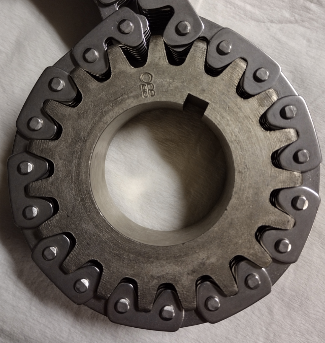
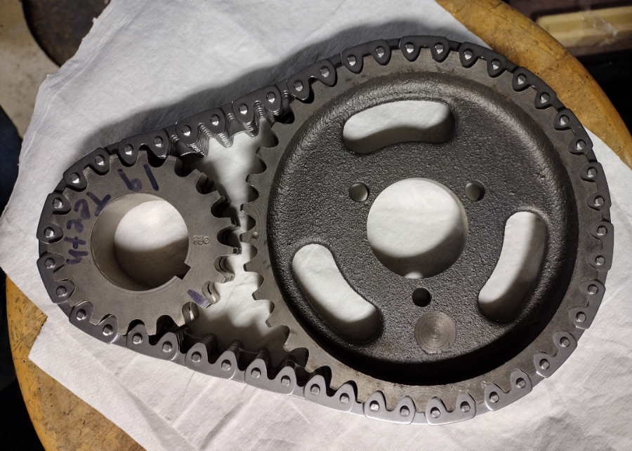
Update: I received a new cam sprocket and new crankshaft sprocket (NOS, actually) from Vintage Power Wagons, who had sold me the first set of parts 4-1/2 years ago. They arrived at no charge. Jens was the one who took my call, and he said they have occasionally seen NOS sprockets that must not have gone through final machining and don't fit right. I must have gotten some of those in the first go-around. I tried them out this evening, and the new camshaft sprocket fits the chain really well; the new crank sprocket, not so much, with visible gapping between the chain and the roots of the sprocket teeth (see first photo), although the two sprockets could actually fit within the chain and clear each other (unlike before), so that's an improvement. So I tried the previous crank sprocket on the chain again and it fits very well. Between the new cam sprocket and the first crank sprocket, it looks like I have a viable timing set (second photo). I guess I won't know completely for certain until I install the parts on the engine, but I have high confidence today things are right again. I asked Jens if Melling makes timing sprockets, and he said no, only the chain, so a completely matched set won't be possible, but I'm ok with that.
-
Full Flow Oil Filter Part Number and Applications
Matt Wilson replied to Matt Wilson's topic in P15-D24 Forum
I don't suppose you can tell me how many teeth are on the flywheels that mate with those shorter starters? Or how many teeth are on those starters, or maybe both? I can count the teeth on mine when I get home. I know the flathead flywheels and starters had at least a couple of different tooth counts over the years. A mismatch in that regard would throw a starter swap out of the running, unless I want to swap flywheels or ring gears (which I don't).

