


Matt Wilson
-
Posts
641 -
Joined
-
Last visited
-
Days Won
2
Content Type
Links Directory
Profiles
Articles
Forums
Downloads
Store
Gallery
Blogs
Events
Everything posted by Matt Wilson
-
Ok, that sounds great, and is reassuring. It was just something I noticed, so I thought I'd mention it.
-
I read through your entire set of posts this morning. I'm really enjoying seeing the progress, and there always something I can learn from reading about projects like this. Can't wait to hear how your engine runs once you get out started and dialed in. The brake and clutch pedals look as though they've been cut and welded back together, right at the elbow of each pedal. Am I seeing that correctly? If so, I hope the brake pedal welding was good. You obviously don't want that to let go during a hard panic stop. Not trying to alarm or criticize anyone in any way, but just bringing up my observation and a potential concern.
-
Sounds like the original poster got his situation addressed, but just for everyone's awareness, some ranges of year models used a chain and sprocket set that were 1/2" thick, while other year model ranges used 1" thick parts. I remember Vintage Power Wagons bringing this up to me when I ordered parts from them several years ago. And if I recall correctly, I believe the timing cover depth was also different to accommodate these different chain and sprocket thicknesses. VPW encouraged me to get the thicker parts, as they are more durable (makes sense), and that was fine for me, since that was what came off my engine to begin with.
-
Just so you're aware, many of the filter inserts/elements were cloth, rather than paper. So don't be surprised if you open up your filter housing and find an element that looks like it is encased in a sock.
-
I highly recommend thinking carefully about using a ridge reamer. I've had two experienced machinists from two different machine shops, 20 years apart, who told me not to use a ridge reamer, as those reamers will remove the only remaining unworn material that is square with the crankshaft, making it much more difficult to get the newly bored cylinders square to the crank. Also, it is difficult to avoid removing too much material, even if you watch closely and think you are stopping as soon as you have removed only the ridge. When I took one of my engines to one of those machinists, I was certain that I had been very careful and that the cylinders could be cleaned up by going no more than 0.020" oversize, but since I had used a ridge reamer, the machinst said he had to go 0.030" over. Not a huge deal, but I would rather have kept it to 0.020" in the interest of future rebuildability. And just as a matter of principal, I prefer not to waste material. I asked these machinists what to do if I need to remove the pistons and don't use a ridge reamer, and they both said I should have just pounded the pistons out, either through the top or through the bottom of the block. It would destroy them, but that's not a big deal, since they won't be reused anyway. The only downside is that I wouldn't have had any show pieces to hang on the wall.
-
Here's a photo of one of my bearing shells for a 25" engine (237/251/265 cid), with the oversize and other info stamped into the back. The characters are impression-stamped into the surface. There doesn't appear to be any raised material, but the characters are definitely stamped into the surface. I can catch them with my finger nails. These are new bearings (as of a few years ago), not NOS, that had Sealed Power on the boxes, and you can see F/m (I believe that's Federal Mogul) in the photo. I think Federal Mogul owns Sealed Power.

-
As was mentioned above, you'll need to figure out how to keep the sanding debris for getting into the oil passages, or figure how to get it out afterward. Maybe put a small piece of tape over the hole leading to the passage in each crankshaft journal, and sand around the tape.
-
As others have said, the Dodge/Chrysler/Plymouth/DeSoto flathead sixes have hardened exhaust valve seats from the factory, and they are very capable of handling modern, unleaded gas without any issue. They came that way starting in 1933 or 1934, and remained that way throughout all years that they were produced, which was well into the 1970's. So you don't need to worry about that.
-
Yes, I saw your post from the other day and I'm glad to be of help. I think nobody has talked about this because not very many rod bolts have cut threads. I think those went out in the early days, and it's probably one of those things that most people don't pay much attention to or know about. That's a good idea to ask about offset reaming. Good luck with getting your rods and bolts to play well together!
-
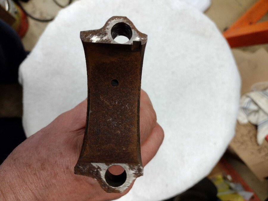
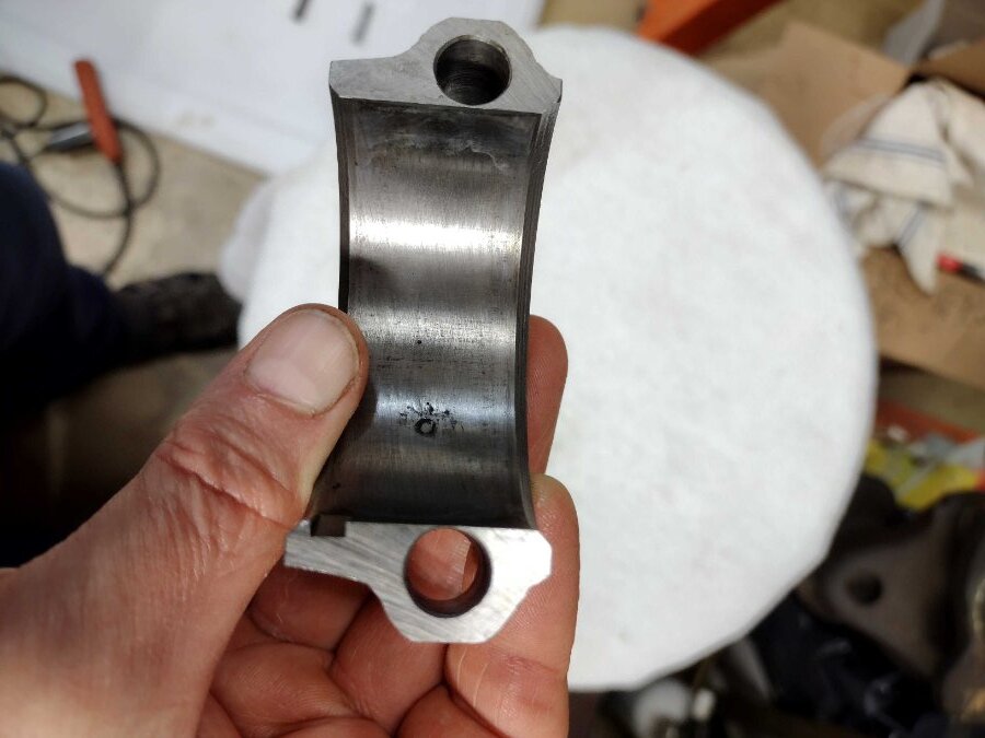
I dug out some rods and bolts and took some measurements this evening. The first photo shows a few rod bolts lined up side-by-side, with some dimensions and commentary for each one. You can see that the threaded section outer diameters don't differ greatly from bolt to bolt, and not as much as the bolts in your photo. The threaded section of the original 230 rod bolt (3rd from left) has an OD that is not consistent. It seems to be largest at the end of the bolt, then gets a little smaller heading toward the shank, and then gets larger again as we continue approaching the shank. I take that to mean that the bolt has been "necked down" due to yielding of the bolt in that region. Best not to use a bolt in that condition. You can see that my assessment of that bolt is that it has cut threads, whereas the other three appear to have rolled threads, since the threaded sections are larger in diameter than the adjacent shank section in each bolt. The next few photos show a couple of 230 rods and caps, focusing on the thickness of the wall between the bolt hole and the bearing saddle. One of these rods is an old rusty one that is not usable and has been hanging in my garage as wall art. The original-style bolt in my first photo was taken from this rod. I measured the thickness of that wall and then sanded away the rust from the bearing saddle (bolt hole wasn't rusty) and the measurement didn't change (reads about 0.015"). As you can see in the end view of that same rod, the wall at the opposite hole is a little thicker (I think it was about 0.030"). I also measured the cap from another 230 rod that has been preserved in a plastic bag with some oil (see photo). It shows about 0.006" wall thickness, which seems extremely thin, but this cap and its rod were running just fine in an engine I rebuilt over 20 years ago. I disassembled that engine for other reasons about 9 - 10 years ago. This cap and its rod were in service with the ARP bolt shown in the first photo. As long as there is no burr or other raised metal to interfere with the fit of the bearing within the rod, I suppose there won't be any issue with such a thin wall. I also measured the wall thickness of a 251 rod (not pictured) and it was about 0.012" at one hole (opposite hole's wall was thicker). Again, this is a rod that had been run that way, and I believe it was factory-original. Hopefully this is of some help. Let me know if you want more photos or measurements.


-
Here's a possibility. I wonder if the Dodge rod bolts have threads that are cut, while the Pontiac rod bolts have rolled threads. Rolled threads are formed by dies that displace (smash) the material into the shape of threads, without removing any material. This results in threads that have larger outside diameter than the adjacent shank section of the bolt. On the other hand, cut threads are just that - they are made by cutting material away to achieve the thread shape, so the threaded section diameter will not be any larger than the diameter of the adjacent shank. It's kind of hard to tell from your photo, but it looks like that might be the situation. If so, then accordingly, the Dodge rod might be made with smaller bolt holes to snugly fit its cut-thread bolts, but the Pontiac bolts, with their rolled threads are too large to fit. I have a couple of Dodge 230 flathead rods at home, along with their bolts, and I can tell you that the threads in those bolts have the appearance of being cut, which surprised me, since I have seen other Dodge flatheads that have the appearance of having rolled threads. I have no reason to think that those are not the original bolts, and perhaps they were early rods that used cut-thread bolts. I could take some measurements and photos of those rods and bolts some time in the next few days and we can see if they match the dimensions of your bolts. We can also see how thin my other rods are (the ones that used rolled-thread bolts) in the wall between the bolt holes and the bearing saddles. I remember them being pretty thin. We might find that you have room to ream out the bolt holes in your rods to accommodate the slightly larger Pontiac bolts, or some aftermarket bolts, such as those from ARP. From the strength and durability (fatigue) standpoint, the bolts containing rolled threads are very much preferred. I believe virtually every manufacturer uses those types of rod bolts nowadays and have for many, many decades. I remember seeing early rod bolts from other engine makes that used cut-thread bolts, but I think most everyone moved away from that type of design long ago.
-
Thanks, Jim! That's helpful.
-
Hi Jim, I see that you used Crower custom bushings for the connecting rods (small end) and 0.866 diameter wrist pins. Do you know the OD of the installed bushings? That would be the same as the ID of the rods. I'm looking to determine the wall thickness of the bushings after they were installed and honed to fit the pins. Are these bushings made completely of bronze, or are they steel-backed, as some bushings I've seen? Thanks.
-
Thanks, guys, I appreciate the inputs. The machine shop did not use a torque plate. One was not readily available at the time, and I didn't see it as necessary. As for digging too deep, I would agree if I was running OEM-style pistons and rings, but I will be running modern forged pistons and modern low-tension rings. The first person who told me that my rings would not tolerate my misshapen cylinders was Freewheeling Tony Smith. He works with these engines an awful lot (machine work, assembly, etc.), including the incorporation of upgrades to use modern parts like I'm doing. He really seems to know his stuff and has an excellent reputation in the Dodge/Chrysler flathead community. Since my last post, I also received word from someone who knows a Total Seal tech rep, and he conveyed my situation to him. The rep said the same thing - that the rings are not forgiving of this type of situation, and he recommended I immediately get the bores straightened. Of course, that will require I get new, larger pistons and rings. Sigh.... If I want to use modern rings, it seems that the old standard of several thousandths of taper or out of round being acceptable is no longer applicable. I've also read some things to indicate that torque plates are recommended (some say necessary) for low-tension rings. I don't know if that's really 100% true or not, but in any case, since I will be re-doing this aspect of the engine, I asked Freewheeling Tony if he has a torque plate for this engine. He said he doesn't, but would enjoy fabricating one and would rent it to me. I plan to go that route. With all the effort and money I've put into the rest of this engine, I figure I'll go the whole nine yards on this part of it too. It will be a couple of months or so before he has time to make it. That will work out ok, because it will be a couple of months before new pistons would arrive anyway.
-
You're right, I am leaning in a direction and yes, I've talked to 4 people. I question whether the two from JE Pistons were "experts," as one is a salesman (although he seems to be knowledgeable) and the other one is in tech support but changed his answer for no apparent reason, and neither person could give me a taper spec (seems like that would be basic available info). The other two I spoke to are machinists, but again, one gave me one answer and the other gave me the opposite answer. The one who directed me to re-do it all with new pistons, rings and overboring was the only guy to give me some technical reasons that sounded pretty solid. The others literally just said "it'll be fine" or "I wouldn't use them as is." I'm thinking that, as painful as it is (financially), I should lean toward the side of caution by buying new pistons, rings and having the cylinders bored more oversize so they will (hopefully) be straight and round. At this point, as you alluded to, I am kind of looking for confirmation that this is the right decision so that my wounds won't hurt as badly as I'm licking them. On the other hand, if someone has some really good reasons that I don't need to go that route, I'm still open to listening.
-
I'm running some custom-made forged pistons by JE Pistons. The bores are about 3.482", which is nearly 0.045" oversize from the original bore size for this 251 block that I'm using to build a 265.
-
Following up on this topic to describe the progress (or regress, as the case may be). Sorry - another long post.... I took my block back to the machine shop to remove the cylinder rust that I had caused. He honed all the cylinders, removing 0.0005 (half-thousandth) from most and closer to 0.001" from #6. He and I discussed using Line2Line piston skirt coating to take up the excess clearance. He highly recommended it as a durable long-lasting coating, which matches what I've read too (good for the life of the engine). Ok, no problem. I can deal with that. But I have a dial bore gage, so I decided to take my own cylinder measurements when I got home. I found that all six bores have a "bulge" near the top, as seen in the image below. This "bulge" makes the diameter about 0.0006 - 0.0007" larger than the rest of the bore over a distance of about 2" vertically. Below the bulge, the diameter drops back down, almost to it's value at the top (but not quite). I called the machinist and he acknowledged the presence of the bulge and said that it has to do with the diamond hone equipment he uses not being great for opening up the bores by very small amounts. His boring/honing machine is brand-new as of last year and did a fabulous job on my cylinders when I brought him my new pistons at that time. The taper and out-of-round were no more than 0.0002" total variation, but now opening up the cylinders by such small amounts to clean up the rust was not a job the machine is suited for. In any case, he said he only measured 0.0005" in the bulge, not 0.0007" that I was getting and that it would be fine. I'm confident in my measurements. I'm using a set of thin modern rings with thicknesses of 1.5 mm top, 1.5 mm 2nd, 4 mm oil (0.058", 0.058", 0.157"). It's a little tough to find specs on thin rings, but what I can find indicates only small amounts of taper are acceptable, ranging from 0.0002 - 0.0008". These are for recent-model Fords, VWs and Chevy LS engines. And that allowable taper is over the entire cylinder length, whereas the bulge in mine are over only 2" length, so probably a worse situation. In the old days, with thick high-tension rings, taper of 0.010" or even 0.020" was acceptable. I called the ring manufacturer, JE Pistons, and talked to two people - one said the rings would be fine, and the other first said they would be fine, but then inexplicably made a 180, saying he wouldn't run them in my "bulged" cylinders. Neither one could give me a taper spec. Finally, I spoke with someone familiar to some of us, who is respected and does lots of work on these engines, including upgrades to use modern pistons and rings, and he said the bulge was too large for modern rings, especially considering the short distance over which the bulge takes place. He said the lower tension won't follow the diameter variation, leading to poor ring sealing and shorter life. If I decide I can't use the cylinders as they are, then my only option is to buy new larger pistons and have the cylinders bored to a larger oversize. I think I'm inclined to do that, based on the info I've gotten so far, but I wanted to ask you guys and gals for your input before I make such a big (expensive) decision. Keep in mind that I'm rebuilding this engine for longevity, as I intend to drive it and put miles on it. Thanks for your input.

-
I've read about this pump seizing issue for a couple of years now, or more. I've read about enough instances that I see it as an ongoing or recurring manufacturing problem. There are probably hundreds, or maybe even thousands of these pumps that get sold each year, and I suspect most of them don't have an issue (although I don't know this for sure), but there are enough that do have issues that the problem would seem to warrant more attention by Melling. But what I understand is that Melling almost invariably claims that it's caused by the installer failing to follow the directions that require submerging the pump in oil and spinning the shaft until all air bubbles are eliminated. The trouble with that argument is, there are a lot of folks who say they followed the procedure carefully and to a "T" and thoroughly removed all bubbles and the pump still seized. Upon disassembly, people are finding that the shaft has seized to the housing. The exact culprit is uncertain, but it thought to be either too little clearance between the shaft and housing or a shaft that is not as straight as it should be, or maybe there's still some remaining air pocket that's trapped around the shaft, or maybe a burr at the little oil hole in the housing that feeds the shaft. One guy on the Facebook Flathead 6 group, Ken Holmes, rebuilds these engines exclusively (for customers), and he employs a run-in procedure that involves submerging every pump in oil for 24 hours and then using his milling machine to spin the pump shaft for a period of time, with the pump still fully submerged. Most pumps have not been an issue for him, but even he has had one that seized up during this procedure. As a result of all this, I plan to do like a couple of you guys and reuse the pump out of my previous engine, which has only has around 7000 - 8000 miles, instead of the new Melling pump I bought.
-
Car and engine look great! And wow, 102K miles and still running well. I like hearing those kinds of stories. Any significant work done to the engine since new (or since last rebuild)? Anything special about the engine that has made it last that long? I know some of these flathead sizes can go that many miles or more, but I also hear about a lot that don't.
-
The brass coolant distribution tube I bought off eBay a few years ago was advertised as NOS. If it came with any factory packaging, I don't have it any longer, and I don't see any factory markings on the tube itself, but it certainly looks like it's been sitting on a shelf for 70 years, and I don't know of any aftermarket manufacturers who have made them out of brass. So I think it is almost certainly an OEM piece, and if there was any issue with galvanic corrosion, Chrysler corporation would not have used or sold such pieces. Every time I've read about anyone who has experience with brass tubes, they indicate that the brass ones don't rust, even after many decades in an engine block. Definitely cannot say that about the steel ones. Same goes for the brass vs. steel core plugs (freeze plugs), so I bought some of those as well and will use them whenever I get around to completing my flathead engine build.
-
Borescope - interesting find
Matt Wilson replied to Matt Wilson's topic in Mopar Flathead Truck Forum
I agree. It's really interesting and helpful to be able to see in there. -
Many aftermarket bearings have been made that way, but it's not correct. It will restrict oil flow to the bearing. You'll need to take a file or Dremel tool with appropriate attachment and open up the hole in the bearing to match the oblong shape of the hole in the engine block.
-
I bought a new Offy for my 230, over 20 years ago, for under $200 and never used it. I still have it, new in the box, with linkage and everything. I guess I'll sell it one of these days, as I have no plans for the 230. Instead, I'm building up a 265.
-
Interesting thought..... I haven't assembled the pickup yet, so that's something for me to think about and look at. Maybe there's another way for me to put some space between the new screen and the cover. Food for thought. Thanks!
-
Looks like an interesting project. It will be cool to see the updates. Also, I should mention they I'm shocked at the price of the Offy manifold. I had to look them up for myself, to verify the price you stated. My memory (which could be faulty) says they were being sold for around $200 just 5 - 6 years ago. Or maybe it was closer to $300, but either way, that was much less than the current pricing. I definitely remember a time when they sold for under $200, although that may have been longer ago - say 15+ years ago(?).

