


Racer-X-
-
Posts
124 -
Joined
-
Last visited
-
Days Won
1
Recent Profile Visitors
965 profile views


-
IIRC, the gallery here lets you upload (slightly)larger pics. Plus you can organize them and post several pics, with a link/sample image in your post. But I've had to resize pics smaller to post them here, even in the galleries.
-
Whatever pump you go with, be sure when you wire it that you include a fuel pump relay or switch that cuts the pump off when the engine stops rotating. Your life may depend on it. I had a friend who had a street "beater" car that had been modified where the fuel pump ran whenever the key was on. He got into a moderate collision in that car and spent almost a year in the hospital with severe burns because the fuel pump kept running after the fuel line broke and was spraying fuel on his exhaust pipes. Other than the burns, he suffered a broken leg and a mild concussion from the impact. That's how I wire a 5 pin relay for a fuel pump. The purple wire provides power to the pump when the starter is actually cranking. This is for priming purposes to get the thing running. The gray (or pink) wire barely shows, but is on with the key in the "run" position to power the relay coil, and the oil pressure switch provides ground to the coil when there is oil pressure. When the engine stops, the oil pressure drops away and the pump stops running.

-
I haven't seen their kit before. They use a GM caliper that's often very badly misused. It's hard to tell from the picture, but on this one, there's at least a chance that the result is reasonably safe, although not exactly what that caliper needs to work as GM designed it to work. At least there's a caliper stop plate shown. The test for GM brakes with this caliper or similar GM calipers with the slider pins is this: Place a big C clamp over the outer pad and the back of the caliper. Tighten it down to "apply" the pads to the rotor. Try to turn the rotor to verify that you've got it stopped and locked down with the brake pads. Now pull out the slider pins and try to turn the rotor. If it turns further with the slider pins removed than it does with the slider pins installed, the kit is absolutely unsafe to use. It's using the slider guide pins to apply the braking force. Those pins aren't designed for braking force loads, they are only there to retain the caliper when the brakes aren't applied. If the caliper doesn't move with the pads clamped to the rotor and the guide pins removed, then it's at least somewhat safe. In all GM applications, the tab that stops the forward motion of the caliper is centered between the pads over the center of the rotor vents. That's so that stopping the vehicle doesn't put a twisting force on the caliper and it's mounting system. That's definitely not the case on this kit, but it's possible that at least it isn't abusing the pins to stop the car like a lot of other kits.
-
 @JBNeal I look forward to seeing your write up on this. Does it matter if the 6V supply to these motors is positive ground or negative ground? This is going in a 12V Negative ground system, using a "buck converter" which shares ground (and therefore shares ground polarity) between the 12V input and the 6V output.
 -
New master cylinder from Rock Auto? - Sleeved instead
Racer-X- replied to motoMark's topic in P15-D24 Forum
I have bought master cylinders (several, for different modern cars) from RockAuto.com and got exactly what was advertised at a great price. The "name brands" like AC Delco and Raybestos were always genuine parts from the named source, never counterfeits. The only issues I've ever had with RockAuto were with "private label" parts on "wholesale closeout" deals. Those are a total crap shoot. About a third of the time, I get just about what they claim it is (or equal quality at least), about half the time, it's misidentified and crap. And the remaining times it's been misidentified, but when I did identify it, it was better than advertised, sometimes a lot better than advertised. For the stuff that was crap, I contacted them through the refund/return process on their web site and submitted pics and often pdfs of printed emails from the company they claimed made it which explained why this wasn't made by them, and I got a refund. Usually I got to keep the part because they didn't think it was worth the shipping to get it back, but it went in my scrap metal bin. If I have time and I feel lucky, I'll still buy some of that "private label, wholesale closeout" stuff, but if I need it soon, I'll stick with the known name brands. If I need it now, there's Napa and the other national change FLAPS, but that costs extra, and often it costs a lot extra, even when you factor in shipping from RA. -
OK. You got me there and I had to look it up. Because I actually know you are correct about most (not all) starter motors. There are several types of DC Motors. Permanent magnet DC motors reverse direction when you reverse the polarity of the power supplied to them. Electromagnetic DC motors use field coils for the magnetic field and can be connected internally a few different ways. Starter motors are typically of this type, and are "series wound." Series wound DC motors always rotate in the same direction, no matter the polarity. The direction can only be changed by changing the polarity of one set of windings, rewiring the motor internally. Typically, the armature coils are reversed to reverse one of these motors, if that's necessary. Series wound DC motors have the highest starting torque and are excellent for starter motors, so that's probably what the starter motor is on yours, and it'll spin the same direction with either positive ground or negative ground. For heater fans and wipers and other applications, both permanent magnet types and electromagnet type motors are used, depending on the application and the choice of the manufacturer. It seems that electromagnetic types do not change direction if you change the polarity at the main power feed. You change the armature polarity to reverse all of those types, and some will also reverse if you change the polarity of the field coils. If you reverse both (switching the main power leads), they operate in the same designed direction. Also, I learned that reversing the direction of a DC motor that's designed to spin only in one direction can cause excessive wear of the brushes. Motors that are designed to be reversed have the brushes beveled on both ends, so that they operate smoothly in both directions. Motors designed for one specific direction have the brushes beveled on one side only, and will have excessive friction and wear out quickly if they are operated in the "wrong" direction. TIL much. Reference links: https://electronics.stackexchange.com/questions/159509/why-motor-continues-to-rotate-in-same-direction-even-after-changing-the-polarity https://www.prorichmotor.com/how-to-change-the-direction-of-a-dc-motor/
-
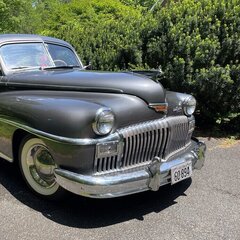
Dash questions, and cowl vent question. Elvis, 1947 DeSoto Custom Sedan
Racer-X- replied to Racer-X-'s topic in P15-D24 Forum
Special tanks to @SteveR who posted this link on another thread about this car. http://www.route66hotrodhigh.com/TechSheets/pdf/Desoto1946-48.pdf The cowl vent parts are shown in a diagram on the 2nd page. Woohoo! -
That's an awesome link. It answered my question yesterday about the cowl vent as well, with a diagram and part numbers for the parts on page 2 of that PDF. And it answered an upcoming question, at least partially, with the alignment specifications and the diagram on the last page showing the front suspension parts. And it does show the wiper wiring in the wiring diagram on page 8 of that PDF. Which makes me feel like "that guy," the one who always asks for more and is never satisfied. Because it doesn't show a diagram or part numbers or any of that for the wiper mechanism. But I've bookmarked that and saved a copy. DC motors reverse direction if you reverse polarity. So it's likely running backwards. And "park" functions vary in complexity and design, but none of them like to run backwards. There's usually a lever that triggers a switch to stop the thing in the "parked" position, at least for ones where the wipers are exposed when parked and park within the normal range of motion while operating. Often running those backwards will bend or damage, possibly even break the piece that triggers the switch. The ones that "retract" to park are even more complicated and usually self destruct if you try to run them backwards. Thanks for the link to Newport. I'll keep that in mind. The contract for this one has an "inclement weather" cancellation clause, so the wipers are more me trying to get them working, less about the car's weekend jobs. Although it would be nice if it didn't have to cancel for light rain, or if it wasn't parked where it is if there's unexpected rain. I'll talk to the owner about it and see if working 12V wipers are worth that to him.
-
I need to get the wipers working. With the drivetrain swap (GM LM7/4L60E), the wiring in the car now is all 12V negative ground. I understand the car was originally 6V, positive ground. So there's going to be a conversion issue. Were these wipers simple on/off. Or I guess it was two speeds, I'm told, Off/Slow/Slower. Did they have a "park" feature that returned them to a fixed position when you shut them off? Or did they just stop wherever you cut the switch off? Will they tolerate the motor running backwards? This is an important question. I have a 6V "buck converter" with 20A capacity for this. I was planning to use that to step the voltage down. Now that I'm looking at it, it's wired with the ground for both the input and output circuits wired together. Those wires (both black) are definitely connected inside the converter. That means that it would be much easier and safer to wire it for 6V, negative ground, even if that results in the motor running backwards, as long as that doesn't destroy anything. If the system is just "on/off", it may be fine. If there's any "park' feature in it, I suspect I'm going to have problems. It would also be handy if there was a diagram of how the wiper motor is supposed to be mounted. Ours is hanging loose, rattling around, with a very loose bolt on it. Here are pics, with notes about what I see as issues in these pics. ^ You can see the loose bolt in this picture. It's at an odd angle through that bracket. Also, I'm guessing that the two slotted screws across from each other with the motor shaft bearing cover in the center, are the two power feeds. Is this correct? How does that work? Power to one is "slower" and power to both of them makes it run "slow" (the faster speed). Or is only one screw terminal powered in each speed? Another pic. This one is a slightly different angle, same end as above. And this: That's a view of the wiper transmission mechanism. I think the really old cloth covered wires may go to the wiper motor? This is a different angle on the loose bolt. I'll try to get better pics tomorrow, but it's tough getting the camera/phone up in there to take better pics.
-
Dash questions, and cowl vent question. Elvis, 1947 DeSoto Custom Sedan
Racer-X- replied to Racer-X-'s topic in P15-D24 Forum
Correct. We have no radio now. Not attached to getting an "original," but wondering if any modern "look alikes" are available for these cars to put in that space. Currently we have two toggle switches which don't seem to do anything, and the headlight switch is up there in the middle of that area, but could be moved. -
Dash questions, and cowl vent question. Elvis, 1947 DeSoto Custom Sedan
Racer-X- replied to Racer-X-'s topic in P15-D24 Forum
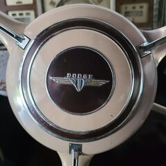
And is that a vertical radio on the left side, with two knobs at the bottom? -
Dash questions, and cowl vent question. Elvis, 1947 DeSoto Custom Sedan
Racer-X- replied to Racer-X-'s topic in P15-D24 Forum
There's definitely a very old electric motor up under the dash. I've got some poor pics of it and I was going to post a separate thread about that. So the switch is where our switch is? Top center, just behind the center post in the windshield. And it is a two speed system. Off, Slower and Slowerer. Got it. -
Dash questions, and cowl vent question. Elvis, 1947 DeSoto Custom Sedan
Racer-X- replied to Racer-X-'s topic in P15-D24 Forum
Awesome, I knew I could count on this forum for answers. @Sam Buchanan, the knob is definitely missing, but that curved beam looking piece is present. @DonaldSmith, is the wiper switch actually up top where we currently have it? I've been wanting to move some stuff around, and your list gives me the "correct" locations for the headlight switch. I may put a start button and more correct key switch in. Our ignition switch and key are currently in the column, and it's a horrible design. Some aftermarket chrome thing from Summit or Speedway. It's a tilt column, which is nice because the wheel is so high unless you tilt it down. But the idiots who designed it used a non-tilt GM switch on the tilt column, and the switch binds with the column tilted down and it tears up the switch. I've had to replace it twice already. -
First question, how "stock" is our dash. Sorry for the glare. There are two switches on the left of the vertical grate section, and one button above that. I'm not sure if they are wired to anything, or what those positions were originally for. The switches are modern, with LED indicators in the tips of the toggle levers. I'm also not sure about the textured looking piece below that curves up at the ends. The right side is a cigarette lighter (not sure if it's wired). The left side has a modern looking Chrome "power" switch with the "standby power" icon is wired to a power antenna in the left rear that isn't currently working, and we don't have a radio in this car yet anyway. Then across the center of that textured area there are 6 additional holes. The left one is round and larger. The rest are squares. Where these original? What were they for? Any pictures or diagrams of "orginal" dash boards would be greatly appreciated. Next question. How do you open the cowl vent. Thats this vent between the hood and the windshield: I somewhat suspect that it's supposed to be connected somehow to a knob of some kind in the center of the flat top of the dash, right behind the windshield. We currently have a windshield wiper switch there which doesn't look "stock" and really doesn't look good at all, and isn't currently connected anyway. I would really like to get that vent working and opening if I could. The windshield wipers are the subject of another thread that I'll be posting soon.
-
Well, spring cleaning first, then spring painting, then installing the newly painted springs with the CalTracks traction bars. This will be kind of a "project build" thread. We're at the point now of installing the CalTracks bars on Elvis, and I need to recondition the rear leaf springs for that. I pulled the right side leaf spring pack off, removed the grease cover and found a big mess there. Also, I've got new shackle bushings, but I didn't have the right bushings for the front spring eyes where they mount to the frame. Thanks to @Sniperhere who got me the part numbers for those. That was discussed over on this thread: None of the local parts stores had them in stock. So I called my nearby DeSoto Parts department, AMS NOS over in Fairmount Georgia. Anthony there had some aftermarket equivalent to the 306448 bushings in stock. So I headed over there to pick them up. As I'm walking in to see Anthony there and get the new bushings, I literally tripped over a pair of leaf springs that looked oddly similar. I asked about them. They were aftermarket springs for the 1949-1952 models of Chrysler cars, and they were virtually identical to what I had. I actually had the original spring with me, and we compared. All dimensions matched. These were designed with round plastic slip pads, and not for grease covers. They were slightly rusty (surface rust), but looked in good shape. The bushings were a bit dry rotted. They didn't look over 20 years old. Dayton 78-425. The paper labels were still on them and still readable. So, I negotiated a price for the used ones (new ones of that part number are still available, BTW), and ended up getting bushings and two new spring packs. Those are rated at 850 pounds each. I'm considering adding 1 upper leaf (not the eye leaf) from the original spring pack for a bit more support and stiffness. One complaint with Elvis is that the rear sags with 3 passengers in the back seat, and luggage in the trunk. Here's my parts and supplies laid out.
