grea235
Members-
Posts
76 -
Joined
-
Last visited
-
Days Won
1
Everything posted by grea235
-
For gears in the front, I used ebay. For OD parts, I used vanpeltsales.com for a 12v solenoid and the big 4inch snap ring. They list parts as Ford, but some fit the plymouths. A couple days ago I called and ordered a balk ring/gear. They are used, but he said they are cleaned, inspected and tightened. I'm pulling my R10 soon to replace the balk ring so we'll see. For $45, I'll take the risk on condition and fit.
-
MORE Hints from the Model Garage (Popular Science, Nov '53)
grea235 replied to Bob Riding's topic in P15-D24 Forum
What a coincidence. I'm currently putting an overdrive together and swapping in a better brake band. When I tighten the lower guide bolt/screw, the band twists forward and drags. It looks like there's too much of a gap betwen the band and the mount. I was going to weld in a shim, but I think I will try a bend over shim like it shows. Thank you very much for posting this!! -
This is on the agenda for me this weekend. I appreciate the insights and options you've all presented. The clarification on the residual valve dissassembly was really helpful. In addition, I'm replacing the rear brake hose and lines.
-
Thank you. It's on the list!
-
Thank you! I will absolutely check that once I get the hub turned down. I believe I have all the parts and the correct attitude. I'm going to check the master cylinder for the residual valve and since I have to drain it anyway, I'm plumbing in the in-line 2/10 valves. I should be starting on it next weekend.
-
This is what's in the 'kit': PLY G30 brackets (2) 9/16 x 3” HHCS (2) 9/16 x 2-1/2” HHCS (2) 9/16 x 1-3/4” HHCS (6) 9/16 hex nuts (6) 9/16 lock washers (2) Metric Banjo bolts (2) Cotter pins (2) Hose locks Everything else has to be purchased separately.
-
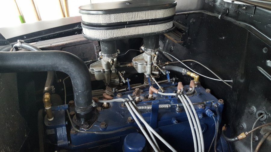
Thanks, I appreciate the info. I've seen them, downloaded and reviewed them. My plan is to go with the wiring in my service manual for now. My only concern with putting the kickdown switch on the throttle linkage is the reality of the operation. I'm running dual carbs, headers and a rebuilt motor. It has quite a punch when I stab the throttle, so to 'kick it down' to actuate the switch may be interesting. I don't have any hills so I will infrequently need to kick it down. We'll see though. The war plan is only good until the first engagement. I want to initially run it locked out to ops check the normal mode, then add in the od wiring and od mode. I can't wait to get it in there.
-
I saw the hubs. I'm passing on them for now. I'm going to go with my own hubs and not stud them unless I absolutely have to. I assumed that they had to get studded for clearance, but apparently not. I can trim down the hub flange. I have the economy DGE G30 coming. I asked for the install guide and they emailed it to me. Ordered all Raybestos off of Rock auto. 179 for everything including shipping. Don't need the dust caps. Calipers are rebuilds and the picture shows pins as well. We'll see. If it helps anyone, this is what they listed for the DGE G30: Part Application NAPA Wagner Raybestos Rotor 1993-96 Ford Probe front 4886318 BD125274 96318(R) Caliper, LH 1979-85 Cad. Eldo front SE4680 TQM25048 RC5248 Caliper, RH 1979-85 Cad. Eldo front SE4679 TQM25049 RC5247 Brake Hose (15”)* 1979 Seville front 36845 F98912 BH36845 Brake Hose (17”)* 1979-82 El Dorado front 36959/36960 F98914/98914 BH36959/3696 Brake pads 1983-92 S10 4WD TS7070AM MX154 EHT154 Dust cap 1983-2010 Ranger 2WD NAPA 735142 Dorman 618-503
-
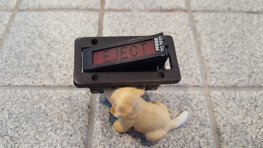
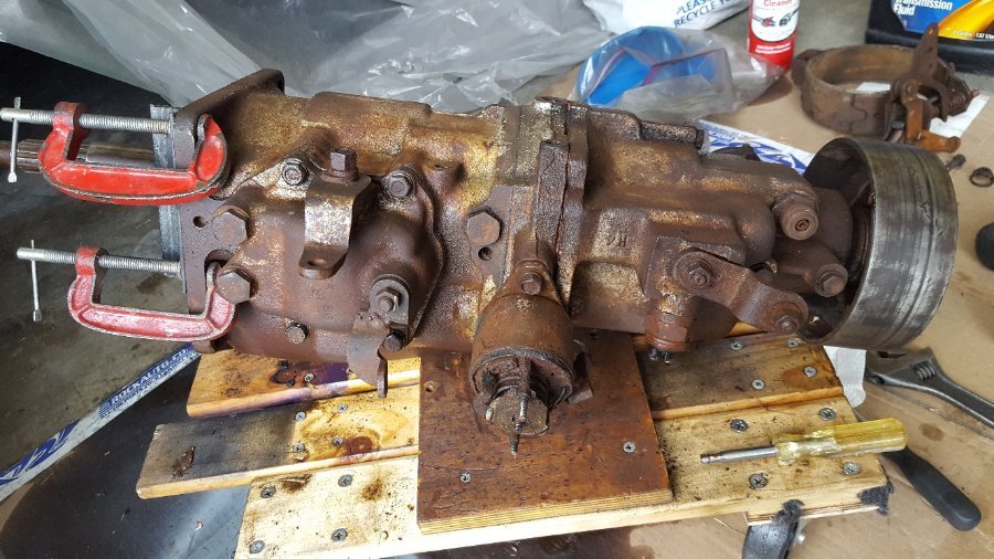
My overdrive is all back together. I appreciate all the posts in the forum. They were a big help. Put in a few new gears in the front and new rear bearing and seal and gaskets. I was able to get a 12v solenoid from Van Pelts right when he got a bunch in. Filled it with fluid and no leaks. I can run through the gears and the pawl is working correctly. I'm waiting till after a car show in August before I put it in. I'm working out the wiring diagram for it. I want an indicator light to tell me when the solenoid is getting power, so I am going to put in an EJECT light that I 'liberated' from benchstock when I worked on F-4 Phantoms along time ago. I'll put on a bracket by the overdrive cable.
-
Makes sense. I will do that. Thank you both!
-
So with these studs, you just drilled out the threads with 1/2 and pressed them in? Just confirming. I ordered the econ kit and the only thing I'm pondering is the stud situation.
-
It took me a bit to get it apart, reading is fundemental. One of the cage gears was stuck, so I gingerly got it unstuck. I verified that the pawl and squirrel cage, I mean sun gear, are working properly. I do need to replace the clutch, low\first and second gears because the rust ate into them just a little too much and for the price and availablity, it's cheaper to replace them now and not after I get it in. The front end gears look really good. I have regular kickdown switch ordered and a used studebaker governer coming in. Hopefully I can get the governer I have working with a studebaker cap. I could have McGyver'd something for the kickdown switch but for the price of a regular switch it wasn't worth it. All my parts are coming in so I am on the overdrive path. Thank you for all your help. Everyone is happy here including my Dolph Lawgrens.
-
Unfortunately, there's no free wheel to it at all, except in neutral, so it looks like I'll neec to split it apart. First though, I'm going to see if a boroscope in the fill plug will reveak anything. Thanks for the help!
-
That's what I thought about the shift levers. I will do that test, thank you!
-
Thank you very much for the info and leads, I sincerely appreciate it. I have the short wheel base, so I will be seeing my driveshaft shop again. I just had a u-joint one built, so I have the original and the new to work with. I saw posts about the speedo gear and will do that and the brake extension, that part should be easy peasy.
-
I've been wanting an overdrive for my 52 Concord for awhile. Finally got one. No kickdown switch or relay or lockout cable. The governor needs a new cap because the sliding plate is rusted in half and unfortunately the 6V solenoid is froze up. I would have to change it anyway because I'm running 12v. I was hoping it would be good and I could sell it to defray the cost of a 12v one. It has also has welded gear selector lever which I assume it in an earlier year car. When I pull mine out, I'll swap the lever out. The plug in the front is being held in because the plug isn't set in correctly. I don't see much wrong from looking inside the fill\drain plugs and lever case. I know that isn't not a complete analysis but I really don't want to split it apart if I don't have to. It had fluid in both front and back, a little brown, but at least no water. I gave $350 for it which I didn't think was too bad given their availability in WA and it was local so no shipping. I've read up on the electrical operation with the governer, solenoid, kickdown and relay operation and I think I can get it operational the way it's suppose to be. It will be a little pricey, but I it will be worth it. The 3 speed part shifts fine, but I have a question about the pawl operation. In neutral, the input and output shafts spin fine. When I put it in 2nd or 3rd, it works fine as in I can turn the input shaft and the output turns. With it in 2nd or 3rd, I can manually engage the pawl with my super sketchy solenoid shaft thingy. The pawl locks in ok, 3/4 inch or so, but it then locks the input shaft to the output shaft and neither spin. Is that normal? I've seen some posts eluding to that and I've got the manual but it doesn't really mention it. I would just like to verify that because it would be painful to get it and and find out something is wrong. Does the input shaft need to be spinning for the rear part to engage and work the overdrive? If that's the case, is there a way to bench test that? Any info would help and be appreciated!
-
-
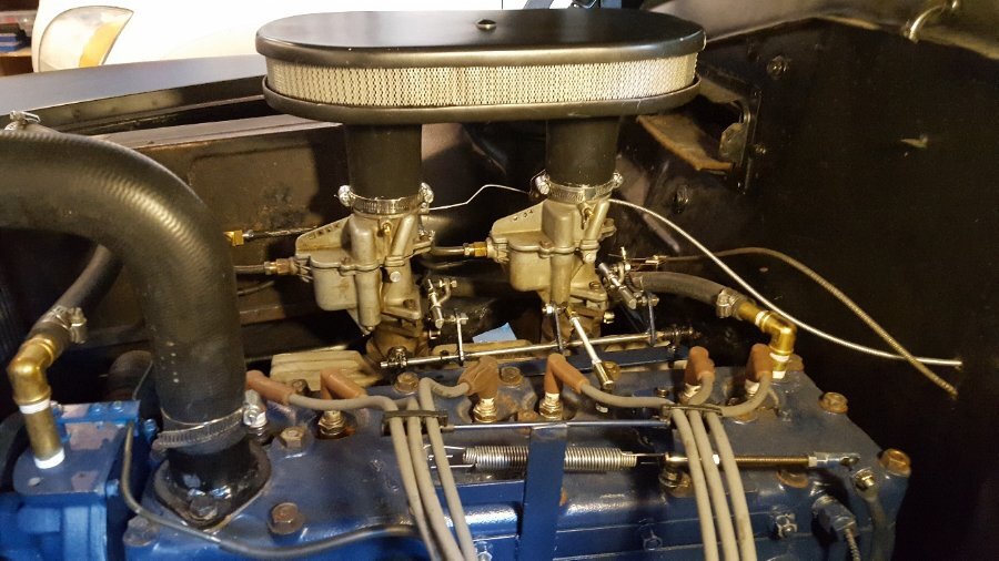
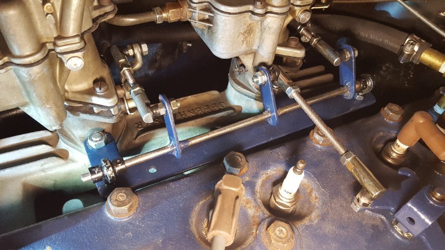
I went over the carb base with tabs welded to flat bar stock so that that the linkage could be removed independently. Used heims and connectors from Ace hardware. I welded the levers to a steel rod. Works well.
-
Thank you very much. That helps a lot.
-
I'm looking for some help on the clutch pedal lift springs on a 1952 Plymouth Concord. While I was diagnosing some clutch shudder, I noticed that my clutch rod between the torque tube and clutch pedal linkage is missing the two clutch pedal rod lift springs. I borrowed the pic below from a member's, post. I hope that was ok. I have a service manual, a motors manual and a old guide book, but they don't really describe the purpose of them. I assume by the name that they help lift the pedal. Is that all they do? If they are missing can they induce any kind of chatter? If I don't replace them is there a risk of the rod holes galling out and causing problems? The only part number that came up in a search on this site or anywhere is a Chrysler number of 1329-486. I don't have a part number book. If someone could verify the part number, I would be eternally grateful. I looked on oldmoparparts, dpmotorparts, obertsmotorparts , moparmall to no avail. If I can't locate some, I will have to bend some up myself or locate used ones. Any help would be appreciated.
-
Thank you for the link! I really appreciate it! I need to replace my exhaust next. The PO used straight pipes and did 45 degree cuts to make curves and it leaks in most of the joints.
-
My 1952 Concord 218 has a split exhaust and its got Allied Blue Streaks on it. Pipes go over the axle and a little past the rear bumper. It's really quiet at idle and low rpm. I don't know what the equivalent muffler is today.
-
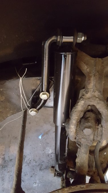
I did this early last year. I didn't have to bend the mounts, but they came close to the upper arm. I put a plate on the outside and a plate with nuts welded on, on the inside. The sting was to help locate the inside plate. Prior to this it boated in turns even with the factory sway bar. The new shock mounts really helped a lot.
-
On my 52 218 out of a Concord, it goes all the way through. I had to seal the threads on it.


