Bmartin
-
Posts
305 -
Joined
-
Last visited
-
Days Won
1
Content Type
Links Directory
Profiles
Articles
Forums
Downloads
Store
Gallery
Blogs
Events
Everything posted by Bmartin
-
Interesting thought. I can see the lines pressed into the copper from the fitting. Not sure if that is any indication of softness. I've been using the washers that came with the calipers. Let me look that up.
-
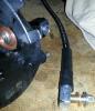
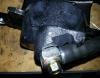
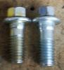
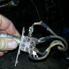
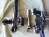
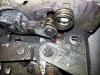
I've been working with Charlie on an issue with the disc brake kit leaking. The soft line is leaking where it attaches to the caliper. I thought I would post up and see if anyone has had similar issues. So far I have replaced the calipers (they seemed to be leaking from the bleeder threads as well and one caliper was sticking). I bought the Chevy application banjo bolts which were a bit shorter to make sure I was not bottoming out. And I've replaced the copper washers with new ones. Both soft lines will not seal against the calipers. I've attached a couple pictures to show what I'm working with. Let me know if you have any ideas. I keep hoping I'm doing something real obvious and I'm just missing it. Difference in Banjo Bolts
-
When you guys cut the coils are you starting at the end of the flat coil (top)and going once round from there or are you cutting the other end that is all round coil(bottom)? I am surprised you get 2" of drop from cutting the top, the bottom makes for sense for 1 coil = 2". But I've been wrong before.
-
Thanks guys, I guess I should have been more clear. I switched to a dual master and 3/16 brake line as part of my disc conversion. The 5/16 input had a hard line with a bad flare, kind of flat. It bent the flare in the block. It sealed to the previous hardline, but nothing else. Since I went dual master, I only needed one of the fittings on the back side. So I have been trying to seal up the 5/16" input. I pulled the plug out and it was wrong, but the threads still looked good. So I put the 1/4" NPT plug in and we'll see what happens. I was looking for other options with a similar layout so I would not have to redo my brand new brake lines to match one of the others with ports in different planes. If this does not work, I'll be shelling out for a NOS one.
-
This is what I have in my car. http://www.ebay.com/itm/1936-1937-1938-1939-1940-1941-Dodge-Plymouth-Chrysler-Brake-T-Switch-MoPaR-/111429804765?pt=Vintage_Car_Truck_Parts_Accessories&hash=item19f1bbe2dd&vxp=mtr#ht_1954wt_1105 The issue with the T's are that they are laid out differently, at least one port is in the verticale plane (When installed in the car). So its difficult to get the existing hard lines to line up. Rich, that is the same one. I was hoping to find a different application that I could use and not 'steal' a stock piece from someone staying original. Plus they are pretty pricey. Its just odd that every other block I've found kicks at least one of the ports up or down. Perhaps another stock one is the easiest choice.
-
I redid all the hard lines during my disc brake conversion and used the stock distribution block. Turns out the 5/16" input flare was flattened by a bad line flare. So it would not seal to any adapters or plugs. I drilled and tapped it out to 1/4" NPT, my buddy was helping me and grabbed a plug and threaded it in, problem is, I don't think it was 1/4" NPT. That was still in the package. So its still leaking. I only need three ports, so I was wondering if anyone has found a block that is similar to the stock one. I don't want to have to redo the hardlines, but most blocks I've seen have the outputs going up and down, not horizontal like the stock one. It does not need to match the stock one, but needs horizontal ports. 3/16" preferred. So far, I have not found anything. Another option is to find someone to braze the hole closed. Anyone with experience in brazing, can this be done well enough to hold pressure? I've seen some used stock ones on Ebay now and then. But they go for $100 and up. So its not my first choice, especially when I'm not a stock braking system. Let me know if you have found anything. Thanks.
-
Nice looking ride, I'd drive it as is. What disc brakes did you use for the front?
-
I need one of these as well. Please post the contact info for the vendor, or PM if that is your preference. Thanks.
-
Thanks for the info. Looks like something along these lines might work. http://www.oreillyauto.com/site/c/detail/CTI0/85433/N0215.oap?ck=Search_N0215_-1_-1&pt=N0215&ppt=C0189 I'll take some measurements of the O.D. of the original and try to match it. Thanks!
-
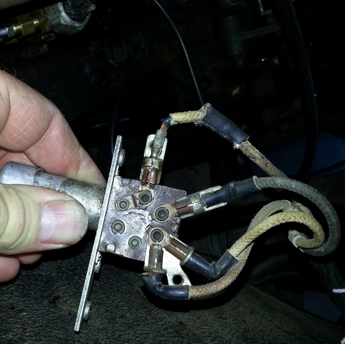
Does anyone have any info on the connections on the back of the headlight footswitch? Are they a crimp type connection? Can I get new ones somewhere and replace the ones on the wire? Mine popped out on a couple of terminals and I can't get them to crimp back in. I tried soldering, but with it in the car, its hard to clean it up and get the solder to flow and stick. For now, the extra solder on the wire side is holding one of them in, makes a tighter fit. I attached a pic below. Maybe I need a different crimp tool, I've go a Kline cutter/crimper, but the crimper is behind the cutting edge. The edge gets in the way when i try to crimp them. Sorry if this has been covered, could not find it using the search.
-
I mocked up the shocks tonight using Charlies mount and a 555003. The bumpstops hit first at full bump and the I only lost about 1/2" of droop. A spacer on the top bump stop would take care of that if required. So I'm guessing the angle of the shock and how it pivots makes the straight measurement a little off. Plus the compressed height of the 555003 was closer to 9.5", they were spec'd somewhere around 10.5". These look to be the same as the 33033's but heavier duty.
-
To piggy back on this thread, when everyone did their shock relocation, did they set it up for full travel - bump stop to bump stop? I'm trying to decide if I need full droop. I can only see needing that in rair occasions when I make a mistake. Since I won't be seeing full droop often, I believe the shock can handle the load on those rare occasions. I definitely do not want the shock to bottom at full bump, that will destoy it quick and that is what is more likely to be experienced with a lowered car. Right now, I need a minimum of 6" of travel for full bump to droop and I'd like to have a 1/2" of wiggle room. The 33033's are 4.5, the 555003's are ~4. 555004's and 5752's are about 5.
-
Rich, just let me say thanks for letting me borrow the miller brake gauge, and especially for all the help you provided. Personally, I don't think you charge enough. The cost of the loan should be the replacement cost. Looking at prices on the bay, you should charge more. That way if something happens, its quickly replaced. Just like at your local parts store, why should it be any different for you? The shipping costs are just the price for doing the loan over long distance. Please keep it up.
-
Very cool. Old tools are almost as much fun as the old cars. I've already got everything back in and installed. Now its time to install the disk brakes.
-
Thanks Rich, but I did not have to do anything with the rear bushings. I ended up measuring from the inside lip of the threaded insert of the LCA. I measured how far it was in from the edge and then marked on the outside and used that for measuring. I got D and E to match up, C is a little difficult to measure since you need to establish a straight line down to the other end of the LCA.
-
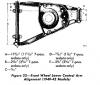
I am reassembling my lower control arms with the steering knuckle support. I need to set the proper alignment of the steering knuckle support with the lower control arm. I am using the diagram below. For measurements D and E, what is your measurement point on the lower control arm? It would seem to indicate the middle of the arm end, but makes more sense to me that you should measure from the inner surface of the control arm. On the steering knuckle support, would you measure from the unfinished casting edge or the edge of the milled nut surface? Also, anyone have a suggestion on the tolerances allowed on these measurements?
-
Thanks Don! That covers it, shim on bottom.
-
I'm getting ready to reassemble everything and I forgot to note the orientation of the king pin bearing. I believe the side that is smaller and fits inside the larger bearing case is the side that faces down. I also believe this is the side with the shim on it. AB did not include an exploded view in their kit and there isn't one in the service manual. Disassembled pic:
-
Found this in a manual online: INSTALLATION OF STEERING KNUCKLES AND BUSHINGS. 1936-42-Install the upper bushing or bearing from top of the steering knuckle as shown in figures 14 and 15, with the trade mark on the bearing at the top. Install the lower bushing and ream bushings to . 7960 to .7975 inch. After assembling the steering knuckle to axle center or support, install the oil seals with the convex side toward the pivot pin. Peening over or staking of the oil seal is unnecessary. On 1939-42 models, select shim ( 46, figs. 23, 24 and 26) to give .003 to .005 inch clearance between steering knuckle support and steering knuckle. http://www.pwchryslerclub.org/PlymouthManual_OCR.pdf
-
Reworking the floor plan is acceptable and I kind of expected that. It would be a good project, I need to learn to work sheet metal. I am most scared of the shift linkage. It seems that even if you are a little off, then you would not get proper shift action - and that is one thing that really affects the driving experience. Perhaps moving to a cable shift linkage affords more leeway. Anyone know if this has been done before or am I charting new territory?
-
It turned out that I did have to remove the spindle and upright as an assembly. I first dropped the rear of the lower control arm by removing the 4 frame bolts and dropped out the spring. Then I removed the front lower control arm bolt and the eccentric bolt at the top of the upright. Pretty easy. The drift pin was mushroomed pretty bad so I took the dremel and cleaned up the edges as best I could. Then I applied a lot of heat to the assembly, enough for grease to flow back out of the drift pin from the flat area. I used an impact hammer to drive it out. Then I let it cool. The other side came out with two hits of a BFH and a brass punch, still on the car. Also, I could not find brass punches at Harbor Freight, or any other normal tool place (HD, Lowes, Sears). Oreilly had them. I think its a tool more specific to cars, so start at auto parts stores in their specialty tool area.
-
I have a 1940 Plymouth Busi Coupe with the factory 201 and 3 speed manual. I am planning on replacing that with a 265 and an overdrive transmission. I know that I will have to move the radiator forward and I am comfortable with that. I will also be swapping to twelve volts with the swap. The catch to this is that I would like to go with a Fluid Drive OD. I want the fluid drive for cruising, right now I wear out my leg in 20 minutes. I know that will require me to move my rear crossmember back and I believe that is doable. The two unknowns I have are the transmission linkage and the starter. Most would just convert to a starter with a solenoid, but I really like the foot pedal start and want to keep it. Will the starter be in the same location as before so that I could just have my current starter switched to 12 volts and run it or will there be both pedal and starter alignment issues? As for the shift linkage, I currently have the linkage type, not the cable type. Will the linkage line up or be shifted back along with the crossmember? Will I need to use one from a different vehicle or even make one from scatch? I had a preliminary discussion with George Asche and hope to have him do the build for me. Any other significant issues I am missing? If you know of any similar build threads to look at, that would be very helpful.
-
So I'm trying to drive out my king pins while on the car. seems like I'm having similar issues. One side stuck out and I could see the flat cut into it. The other side is recessed and looks round (no flat). I'm hammering on the side that sticks out and trying to drive it towards the recessed side. The thing isn't budging and its starting to mushroom the end. I go back and read my manual more carefully and I should be using a brass drift instead of a punch, so there is one issue. Harbor Freight run tomorrow. Is it normal to have to remove the upright as an assembly and work on it outside the car? That seems to be the next step.
-
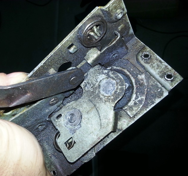
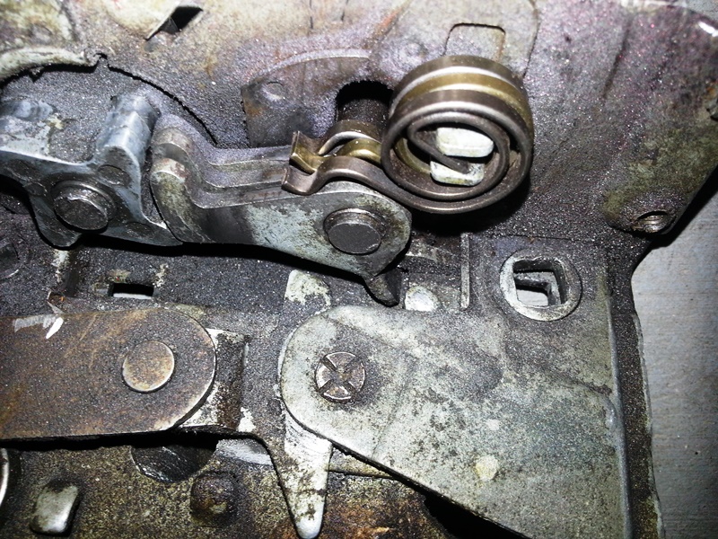
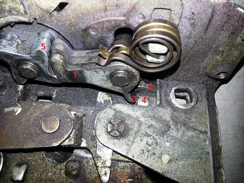
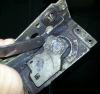
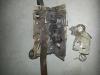
I took apart the latch tonight. I used a dremel to grind down the tow post on the inside of the latch cover. I ground them just flat with the cover so as to leave a little meat to weld to later. Here is a pic with the cover off and one of the springs removed. And here is closeup. To replace the springs, remove each spring and each 'leg' in succession. Then reassemble (leg then spring) in the reverse order. Unfortunately, my original issue still remains after replacing the springs. The latch does not release the star wheel to free spin (open door) until the last millimeter of handle travel. Below is a labeled pic of the latch. I'm going to call the part labeled '1' the leg. The legs keep the star wheel (5) from moving freely so it will latch to the striker on the door jam and hold the door closed. To free up the star wheel the legs must be rotated towards the top of this pic so that they do not contact the stars of the wheel. Both the inside and outside latch have a tab (2 & 4 respectively), that push a tab on the outermost leg (3). The rotates all three legs out of the way of the star wheel towards the top of the picture. My issue is that I must turn either handle to its most extreme, for the start wheel to release. Its almost as if the tabs (2 & 4) have either bent or worn down. I don't think the leg tab (3) is bent since it would be hard to reassemble if it were more to the right of the pic. But I could have it all backwards so if you have some input let me know.

-
Thanks for the input guys. I think I will try and identify some replacement latches first so I have a backup in case I screw it up too badly. My thought process is that I was going to try and find a pin i can use and match it with a snap ring. It would be great to keep it serviceable. We'll see what I can dig up or if my buddies lathe can do something that small.