maok
-
Posts
666 -
Joined
-
Last visited
-
Days Won
1
Content Type
Links Directory
Profiles
Articles
Forums
Downloads
Store
Gallery
Blogs
Events
Classifieds
Everything posted by maok
-
Almost done now. There is always a hiccup but this one didn't test my character.
-
Yes, it does open to the sump. I agree, most likely that is what has happen. I had never worried about it because the shape of that pipe look very factory correct and never crossed my mind. I will have a closer look but I don't think mine has any restriction.
-
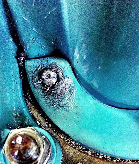
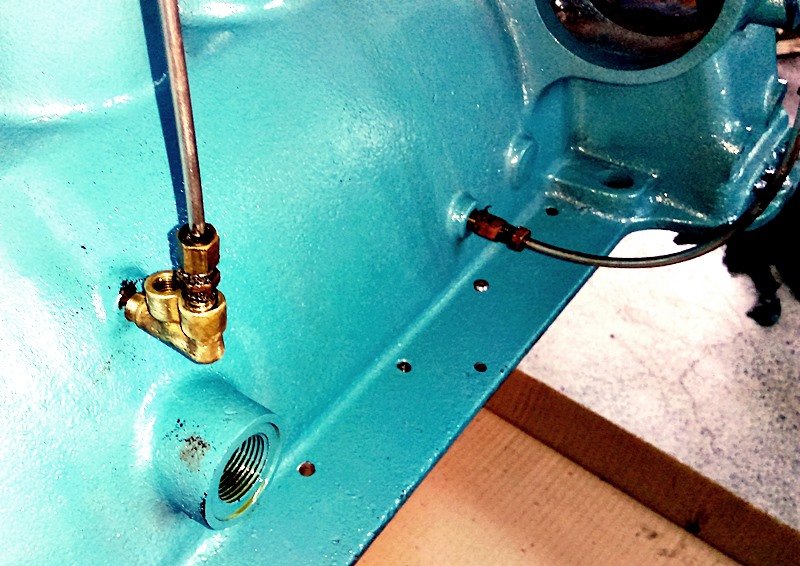
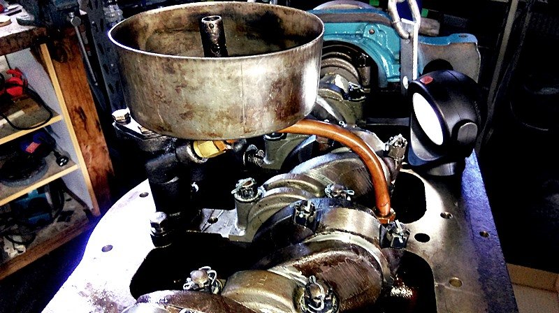
The 'red' coloured fitting is a brass fitting on the end of that ONE metal line Andy...lol Sorry, I should have posted this pic.
-
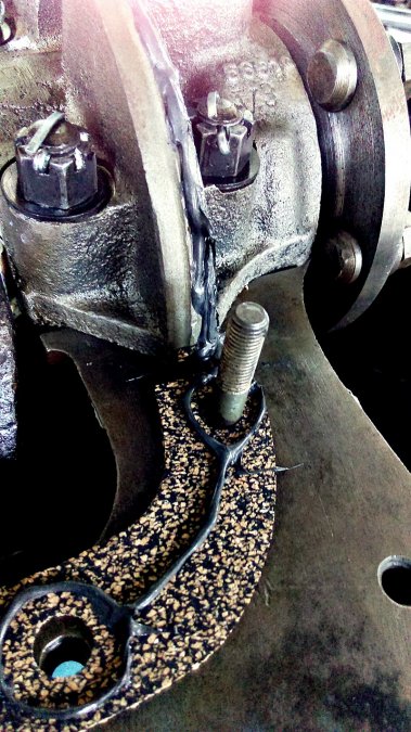
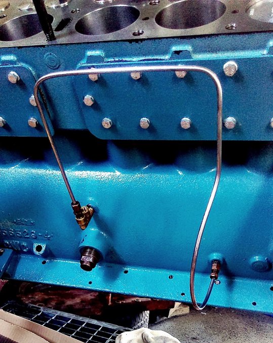
Hi Andy, yes, the large threaded hole is the oil pressure relief valve. The metal line coming out of the 2 outlet brass fitting goes to the other brass fitting that you see lower in the block, which is the sump inlet, ie the outlet of the oil filter would go here.. The metal line is one continuous line, its shaped to go around the starter motor.
-
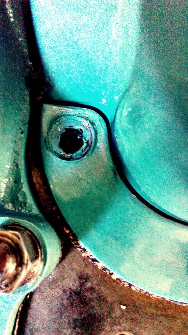
This the outlet for the oil pressure gauge (without the line) and the oil filter, my car didn't have a filter fitted, so the this line has been diverted to the sump inlet. Surely this is not correct, this would relieve the oil pressure in the main gallery?
-
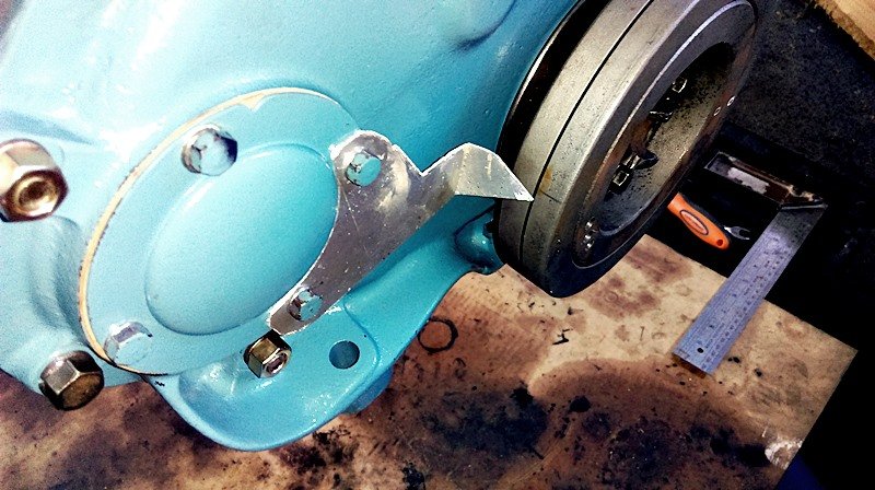
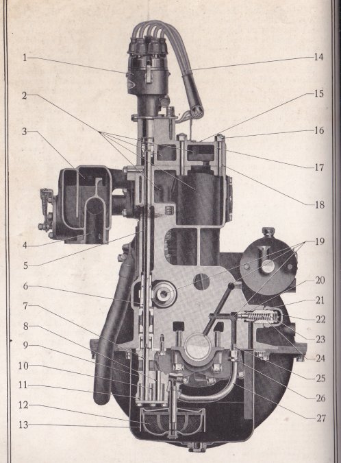
Installed the oil pump today. Packed some Vaseline into it and made sure the slot for the distributor was align correctly at TDC. The slot needs to be parallel to the engine line when #1 piston is at TDC on the firing stroke. This aligns the distributor rotor at about 2pm on the cap which is the #1 spark plug. Looking at the cutaway diagram in the manual, it looks like priming the oil galleries with oil wont much of an issue. Middle pointer of #19 is the outlet for the oil pressure gauge and oil filter tubes, if I pour oil down here it should reach most of the galleries including the oil pump outlet tube. That's my theory anyway. Also made a dodgy TDC marker.
-
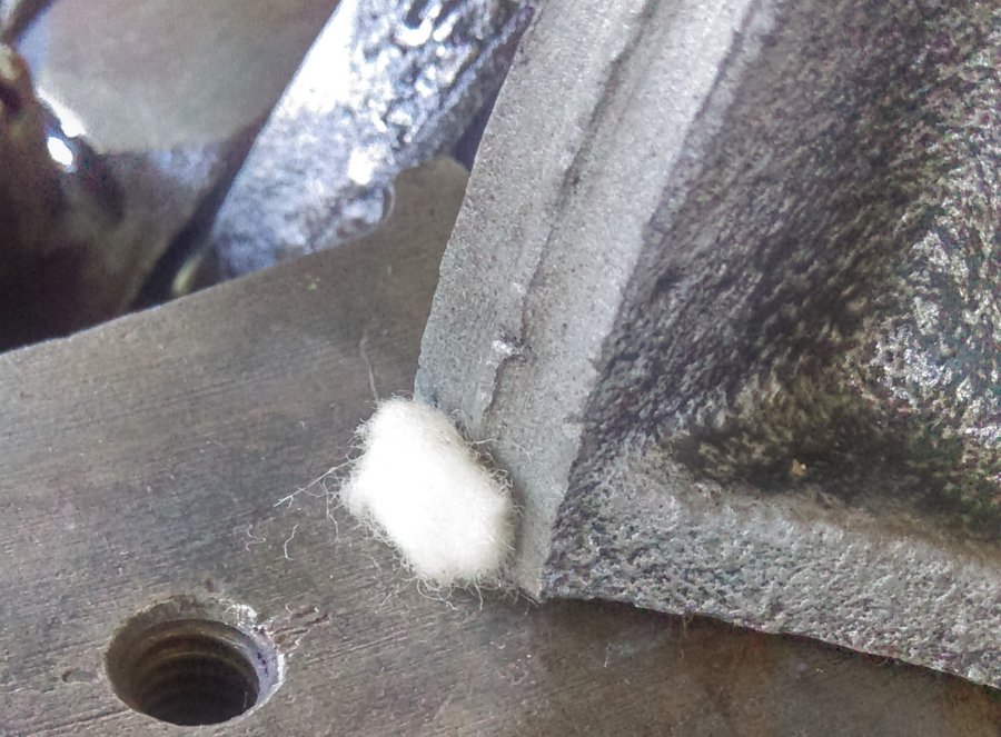
Made the decision on the rear crank cap seal, cork with high temp RTV. This area will need more RTV when I install the sump.

-
Yesterday I did a test with a spare rod bolt and nut, threads started giving way at about 45ftlb so I am sticking with the 30-35ftlb.
-
I have torqued it to 55ft lb with some threadlocker and it also has a star washer. I am having second thoughts about the rod stud nuts at about 30-35ft lb. They are only a 3/8" stud though.
-
No, I was referring to the camshaft bolt, but obviously the later model flatheads don't have a camshaft bolt, hence the reason why I couldn't find a spec for it on the www. Number 3 in the diagram below.
-
Anyone have the torque specs for the camshaft bolt for later model mopar flathead 6's?
-
Its just left over rubberized cork sheet that you can buy from any auto store. I used it to make a sump gasket previously.
-
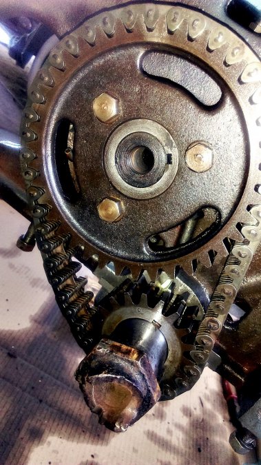
And the new timing chain installed. You can just make out the dots lining up on both the gears. NOTE: For future reference the above timing chain and gear set is from a 1929 series 65 Chrysler, not a series 62
-
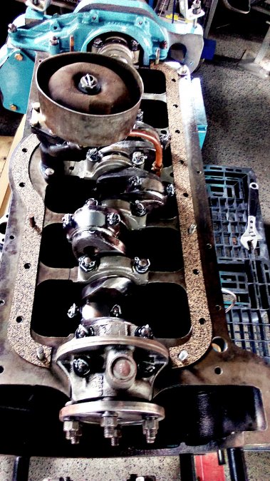
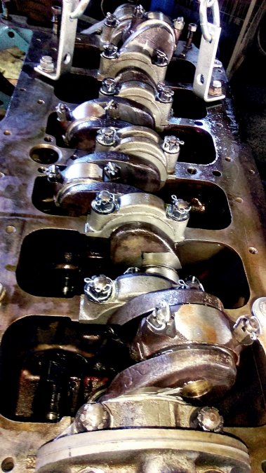
More progress today. Torqued down all the main crank caps (except the rear) and conrod caps, and inserted the split pins. Mains 50ft lb +/- 2. Conrod caps between 30 -35 ft lb. Still need to make a decision on the rear main cap seal. Felt or cork???

-
Only when I'm the passenger.
-
We're on the 'right' side of the car mate...?
-
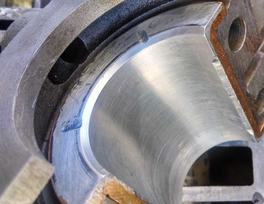
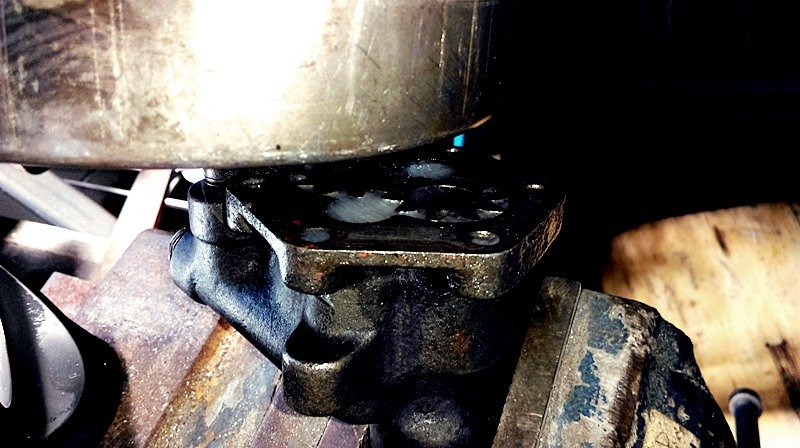
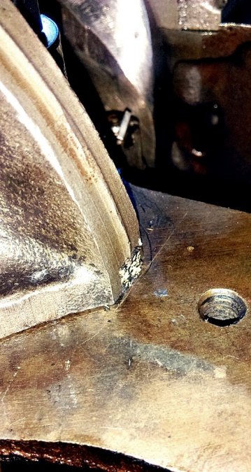
Nope, just an oil catcher integrated into the rear main cap
-
Thanks again chrysler1941, I believe the '28 Plymouth is a 4 cylinder and completely different engine design. The Cadillac pdf is helpful.
-
No need to be sorry mate, I don't even know if its suppose to be felt. Both the engines had felt in there. Cork makes more sense though.
-
Thanks DJ, I will shoot them an email.
-
Doh! Felt was in it when I pull it apart. Now I'm confused, again.
-
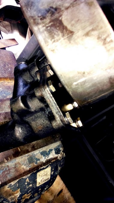
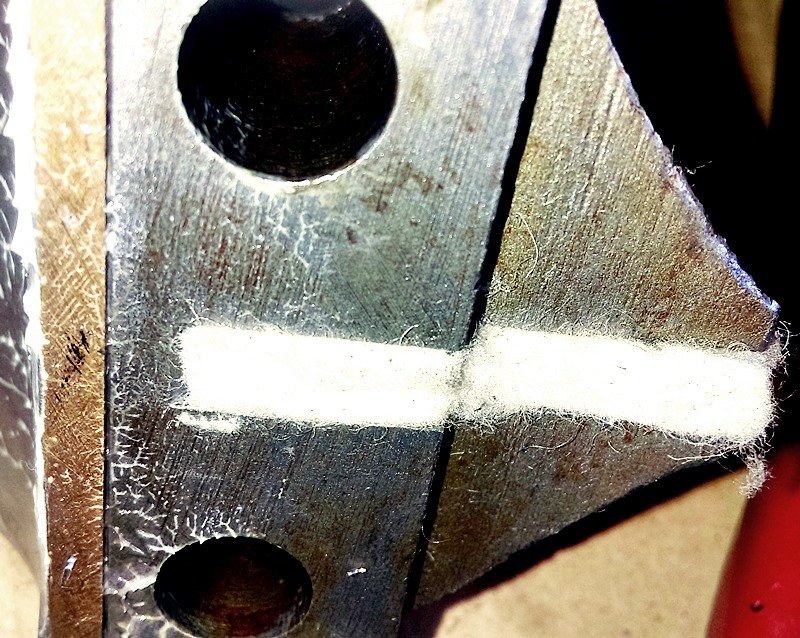
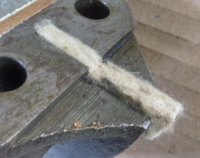
Hey guys, I'm reaching out hoping for someone with experience on how to install these felts;

-
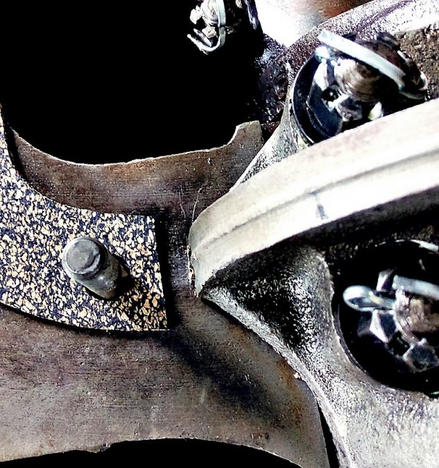
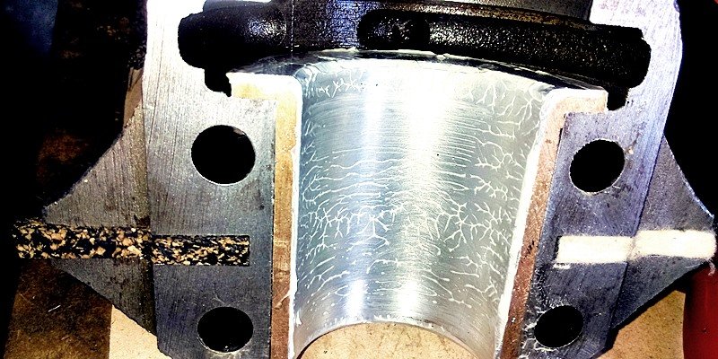
These pics may paint the picture a little clearer Andy; As you can see there is an oil catcher behind the rear main crank journal. The felts are installed in the main cap on the side between the stud holes. The catch in the main cap returns the oil back into the sump. Good idea about starting another thread.

-
Hey mate, thanks for t he reply. The felts are the crank seal, there is no rope seal around the crank like later flathead 6s. But a good idea about using neoprene strip. I had the idea of injecting silicon while the main cap was torqued down via the gap where the felts is poking out, obviously without the felt in there. I am sure the felt is there to stop oil getting past the main cap but I don't understand why its not in front of where the gasket for the oil sump seals. The ridge on the cap is for the oil sump gasket to seal on.
-
Anyone???