clarkoh
-
Posts
20 -
Joined
-
Last visited
Content Type
Links Directory
Profiles
Articles
Forums
Downloads
Store
Gallery
Blogs
Events
Everything posted by clarkoh
-
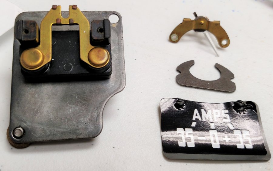
Great stuff. Thanks for the responses. Opened it up for pictures. The brass horseshoe piece conducts the current. The steel piece that looks like a crab is a permanent magnet, which is isolated from the current carrying piece. The brass piece with the meter movement has a small coil on the movement, which is influenced by the current passing by in the horseshoe piece. Simple, not too accurate, but will provide a slightly larger clue than an idiot light. Once it is bolted together, the permanent magnet holds the meter to its zero point, until the flow of current creates deflection. I just have to be careful not to exceed the current carrying capacity of the little piece of brass! Just have to determine which of the battery powered leads to intercept to show charge vs. discharge.
-
1942 Dodge "Job Rated" 218 Bearing Knocking
clarkoh replied to Tubeviper's topic in Mopar Flathead Truck Forum
Might try a can of STP to cushion the rattle? Just my 2 cents. Or some "high test" or some octane booster to allow more timing? -
Thanks. Perfect explanation. I am guessing that it has a shunt inside, through which most of the current flows, minus a small percentage for the meter movement. I looked across the ammeter terminals with my Fluke meter and it appears to be a short circuit, which makes sense. I get the same 0.3 ohm reading as I get putting the meter leads together. Now I am not sure if I can install a shunt in the B+ lead and expect the voltage drop across the shunt to show up as enough to show a deflection in the ammeter?? Anyone ever make this work? In theory, I need to wire the ammeter in the main feed to the ignition switch, fuse box/ charging lead and that would use the circuit as originally intended. But, I am reluctant to create a single point of failure. Unless I wire a panic/bypass switch across it, just in case.
-
Thanks. Good information.
-
Thanks. Sounds like a plan. What wire is routed through the ammeter to allow direct readings?
-
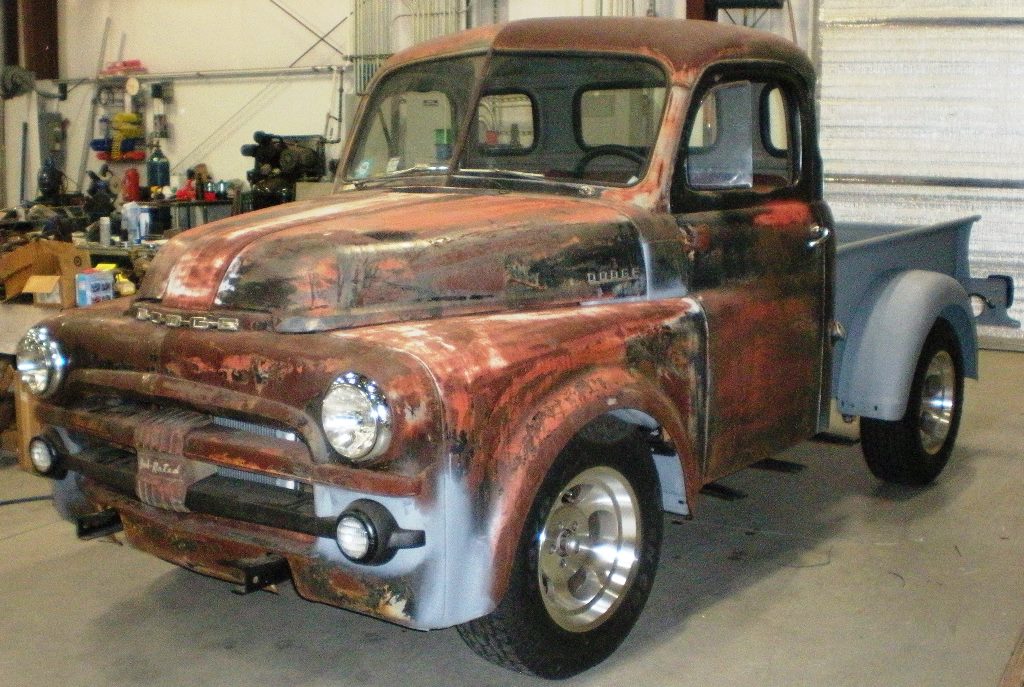
I am in the process of a modern upgrade on a 1948 B pickup. It is now sitting on a shortened 2000 Ram frame and has the Ram driveline and a 4 cylinder Cummins. My question relates to reusing the stock Ammeter. I had the gauge cluster rebuilt and would like to use those gauges on the truck. The water and oil are mechanical, no problem. Is there a way to use the ammeter to register charging/ discharging? I am not using any of the original wiring. How did it know what was happening with the generator/battery ? Is there a shunt somewhere in the old truck wiring? Or did current pass through the meter to indicate direction and amplitude? A schematic of that section of the wiring would be of great assistance. Thanks.
-
Can't figure it out myself. Reaching out for help
clarkoh replied to tom'sB2B's topic in Mopar Flathead Truck Forum
Compression and vacuum are a great place to start. If the carbon is an issue, we used to slowly feed a couple cups of water into the carb while revving the engine slightly. I understood the steam generated helps the carbon pass through the tailpipe. A couple other possibilities might be a warn camshaft lobe or maybe it needs some more timing. A broken valve spring is possible causing a valve to not shut properly? Good luck. -
Wood floor delete from box ideas
clarkoh replied to NiftyFifty's topic in Mopar Flathead Truck Forum
I did a customers 51 with regular plywood, sprayed with bedliner material and added the steel strips on top. Not the greatest looking, but functional and pretty much water proofed. Used 3/4 exterior glued. 3/4" is the trick to keep the crossmembers and the tailgate in the correct plane so the running boards and fender all come out close. -
A guy told me about a mobile blasting outfit, that does a similar set up, on your site. Somewhere around the Charlotte NC area. He introduces some phosphoric acid in the water used to do the wet blasting, which leaves the bare metal ready for primer and prevents any immediate rerusting of the blasted metal. I will have to investigate further. Has anyone heard of this process?? The price this guy paid was very reasonable, too!
-
If all of the components are confirmed good, the advance for the distributor could be the trouble. The vacuum from the engine is used to add more timing through a small diaphram on the side of the distributor. This allows starting with minimal timing, and the vacuum adds timing, once it is running. There are also some centrifical advance pieces that shift the points and rotor once the engine makes some rpm. With it running, watch the timing marks with a timing light. As the engine comes up in rpm, the timing marks should move to show more advance. This will confirm whether the timing advance is actually working.
-
I tried it on 12v. Blows a 20 amp fuse in about 10-15 seconds. Sounds like crap. Kind of high pitched screechy buzzing sound. lol I will get a wire wound resistor around 1 ohm and try it. The coils on either horn read about .7- 1.3 ohms. Thanks for the advise. When I get my truck together, some nice train horns should get the slow riders out of the way!
-
I have 2 horns from Pilothouses, one is 1948, the other is 1951. Similar but different. Both are 6Volt. Will they work on 12 volts?? Can I put a resistor inline to drop the voltage? Also, there are 2 little set screws with locking nuts, can they be used to "tune" the horns?? Thanks Customers truck is ready to ship. Someone else is doing the body work. I got it running and road worthy. Has a 360 from a 1974 truck w/ grannie gear 4 speed, now.

-
Attaching bedside to bed angle strips
clarkoh replied to gtech636p's topic in Mopar Flathead Truck Forum
I just did the steel strips on a customer's 51. Used the spot weld drill tool to remove old. Ground the surface to remove the rust and remains of the old spot welds. Sand blasted and weld-through primer. Punched 1/4" holes at 6" intervals in new strips and plug welded them with a mig. I was careful to clamp the strips on both sides of each hole and skipped around to keep warpage to a minimum. Only signs on the outside of the bed was a very slight penetration. Easily ground away and DA sanded and primed. I am going to use SS on my 48. I plan to punch the holes and use SS filler rod and a tig to weld it. Then mask it off when the bed gets painted. -
I am in the process of finishing a 51. The owner had Fatman Fabrications install a Mustang II front end and a 10 bolt GM rear end. The widths are perfect. Using an 8 x 17" wheel with the backspace at 4" (dead center) the 245 LT 65 17's have about 1 inch of clearance to the sides of the bed and fill the rear wheel openings nicely. We might use a 1/4- 1/2 inch spacer, but might not be needed. The front fenders have a little more width and accommodate the same wheel and tire nicely. Fatman uses an 11" rotor with the large single piston GM caliper. The rotors are drilled for 4 3/4" bolt circle and match the Chevy rear axels. The other way is to use a frame from an S-10 or possibly a Dakota frame? I have seen a few on S-10 frames that worked out very nicely. I am doing things the hard way on my 48.. Using a 2000 Ram 2500 chassis with a Dana 80 R.E. Its too wide, with the stock 8 lug wheels. Inside the rear fenders measure about 70". The outside of the tires are at about 76". I may end up with a set of the flairs from the 1-ton truck for the front fenders and a narrowed R.E.? Or a wheel with a big positive offset? The Ram chassis allows the use of the full sized diesel running gear mated to a 4BT Cummins. NV4500 5 speed with OD should work well with the diesel at highway speeds. Allot depends on if you want to put 'er down in the weeds or go with normal ground clearance.
-
Some of the additives in the newer stuff have to do with the use of aluminum in modern day systems. Aluminum being more chemically reactive than iron or brass, there were issues with it corroding away. We first ran into issues with the Corvettes. They were one of the first cars to use aluminum in their radiators. Now about every car or truck uses it. I recently installed a 360 v8 in a customers 51 Pilot House. It was a junk yard engine and had been sitting for some time. One of the freeze plugs was punctured on each side, I assume by the wrecking yard to make sure it did not freeze. Since the others were not in great shape and the engine was on the floor, we decided to change all of them to brass. I could not believe the sediment that came out. Literally piles of rust, white crusty particles and what appeared to be core sand?. We ended up using a shop vacuum to suck out the junk while scraping with a wire through the freeze plug holes. I bet this junk accounted for a couple pints of coolant volume lost. And the water pump leaked as soon as it got coolant in it. That was before we ever fired the engine. It seems OK for now, but will need a few flushings to get it really cleaned and then it should probably have annual flushing. In my opinion. the hot tank and possibly the use of some acid to remove the scale is the only real way to clean the block and head(s) with water jackets out properly.
-

From the album: Clark's 48 pickup
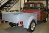
This chassis has around 200,000 miles on it. The only signs of rust are where it was rubbed on. Factory black paint is pretty much intact. The rear section is actually 1 1/2" narrower than the 48. It will fit nicely, oince a new set of body supports are welded on. -

From the album: Clark's 48 pickup
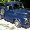
2000 Ram Chassis. Will be shortened 15 inches to match the 48 wbase. All of the pale model Dodge components, including the transmission and Dana 80 will be used. The engine will be a P pump equipped 4BT Cummins. -

From the album: Clark's 48 pickup
48 picked up at an auction. Short, high side bed. The chassis will be replaced with a 2000 Dodge Ram chassis, e/w 4BT cummins and NV4500 transmission. Going for 40 MPG.