-
Posts
66 -
Joined
-
Last visited
-
Days Won
6
65bcoda last won the day on July 6 2024
65bcoda had the most liked content!
Reputation
65 ExcellentProfile Information
-
Gender
Male
-
Location
The glorious state of FL
-
My Project Cars
1965 Barracuda
1949 Chrysler Windsor Coupe
Contact Methods
-
Biography
Male
-
Occupation
Field Operations Manager for FAA support contracts
Converted
-
Location
Florida
-
Interests
Airboating, vintage autos
Recent Profile Visitors
953 profile views
-
Been a little busy here of late helping the wife with storm clean up but finally got to do a bit of work on the Chrysler. Body rust thru repair on the driver's side under the rocker trim, have an identical area on the passenger side to complete as well. Only about an inch will be exposed above the rocker trim. Wire wheeled what I could and applied Ospho as I could get to underneath before covering back up.
-
I have to agree with both Los_Control and Eneto-55 on both of their suggestions, both are doable, I by far am not a fabricator with a full-fledged shop at my disposal but with common tools and patience you can work wonders by gaining the experience. When i first started my '65 Barracuda project I bought a Hobart flux core welder from TSC and my first project was building lower quatres from scratch as replacements were not available neither a good donor car. Just saying some patience and persistence and you can have an acceptable product.
-
Either acquire a piece from a donor car or fabricate your own piece..............only choices I know .
-
Looking at your photo with the top off..........has me scratching my head........LOL
-
Well, not what I expected to get done today but at least it was something............ Fully intended to crawl underneath and get to work on prepping the bottom of the pans for primer but instead opened up the "Jewlery Box" and worked on a project that I have envisioned since originally starting this build. I have a triple dash gauge cluster out of maybe a 64-65 Pontiac Grand Prix / Bonneville / Catalina not sure exactly but found it in a box of trinkets at a swap meet, always figured I could work it into a build. As well as the factory console tach I think from a 1963 Olds StarFire......maybe...anyway I think they go well with the theme of the build. As I need to rebuild the padded dash anyways, I figure to incorporate the triple gauge into the padded dash (Oil, Water & Fuel) and build a similar mount for the Tach under the dash in front of the floor shifter. I fully intend to try to get all the original dash cluster operational.........but who knows..... Still need to cope the ends of the mount to accept the curved dash frame and configure a mounting system that is easily removable, but it will be up flush with the windshield garnish when done. Not 100% sold yet on the rounded end, I was trying to "flow" with the gauge surround, may just chop it off square like I done for the end that butts up to the dash cluster.
-
??? the Ospho was applied about 3-4 -5 months ago on fairly fresh sheet metal with no protection but the Ospho…it converts surface rust to an inert state. A little bit of scotch bright and it is good to prime after proper surface prep /cleaning. i have sand blasted frames and applied Ospho and sat outside for 8 months… properly prep and prime / paint… no issues 10 years later. not sure where you are looking but the only scale in the photos are in the trans tunnel (white powder) A true believer in the product
-
Good afternoon fellas, I got around to cleaning the OSPHO scale off of the treated interior floor pans and the modified firewall, applied the first coat of primer and seam seal to all the joints. Not really looking forward to getting underneath and doing the same to the underside of the floor pans and tunnel but I suppose someone needs to do so eventually......... the wife seems not to be very interested in helping with it no matter what I offer her. Completed framing out the access panel in drivers' floor for future steering gear box removal if needed, just going to wait to fab the panel itself once the body is back on the frame and the gearbox bolted in place to ensure proper panel opening location. Either way I have some fun time allotted this coming weekend to see what else I can get done, still have a small bit of rust thru to attend to on the body....fitting up of brake / clutch pedals....we will see what transpires.
-
-
Well once again found some time to plumb in some 3/8 fuel line from the tank location to the engine bay, 5/16 brake line from the rear forward, front brake line back to firewall (almost). Built a couple brackets here & there for things such as the brake residual valves, E-brake cable mounts etc. Looking forward to getting back to work on the body to finish a few items on the floor / tunnel / access panels as needed before setting the body back on the frame. Still need to do something with the rear housing vent line yet.
-
Another Front Shock Relocation Thread / '49 Chrysler Windsor
65bcoda replied to 65bcoda's topic in P15-D24 Forum
Your welcome................. I tried to straighten out, but I think it may have something to do with the orientation of the phone ?!? -
Another Front Shock Relocation Thread / '49 Chrysler Windsor
65bcoda replied to 65bcoda's topic in P15-D24 Forum
-
Another Front Shock Relocation Thread / '49 Chrysler Windsor
65bcoda posted a topic in P15-D24 Forum
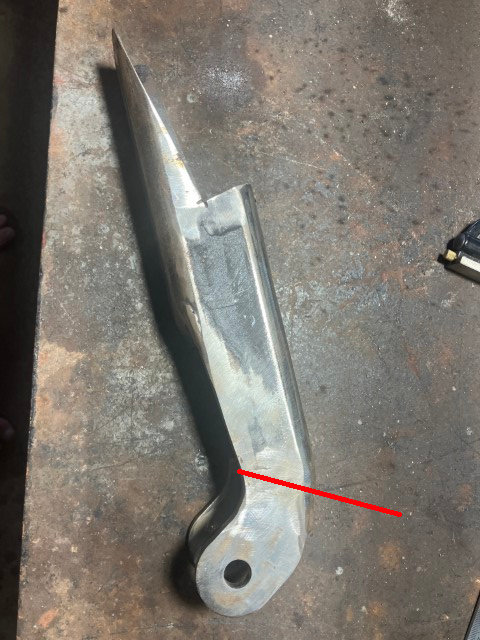
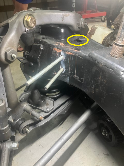
I recently tried my hand at the front shock relocation on the ’49 Chrysler Windsor. After looking into what everyone else has done and tried I originally was going to go the F-1 shock mount route. I ordered a set and once in hand I really was not very impressed with how they needed to be mounted and having the mount pins opposing each other. They are now officially shelf-stock for a possible future project. I checked the full range of movement of the control arms and decided on a 15” +/- ride height for the mid travel point of the shock. The Monroe OEspectrum 37121 shock with a collapsed length of 11.75” and an extended length of 18.38” fit the bill for 3+ movement from the afore mentioned shock ride height of 15”. These 37121 shocks have the ½” bushing on top and the required 5/8” sleeved bushing on the bottom. Of course this shock information is just reference only as each case is different in design and implementation and this is what worked for me. I had some Ruff Stuff specialties angled shock mounts from a previous project and some sections of 2” Reese hitch tubes to work with, so to the sketch pad I went. · The Ruff Stuff Specialties angled shock mounts were made for attachment to a tube so I cleaned the ends up flat. · Cut the 2” tube to a 20 degree angle, from the heel of the angle I sectioned one face of the tube and drove in at an angle and welded to add rigidity to the tube. ( Dotted line) · 5 ½” was determined to be the number from the toe of the 20 degree angle to the top of the frame notch to work with the 15” shock ride height. · The shock mount and tube were both beveled and welding was performed with a root pass before having two final passes and welded inside as well. · Due to the curvature of the frame in the area where the mount needs to be located the amount of material taken out front to back of the bottom notch was “sneaked up on” by trial and error, grind, test fit, grind, test fit until the desired profile was achieved. Laid the completed shock tower on the second and traced the profile to have a mirror image. · Added a piece of flat stock to the back of the notch to sandwich up against the front side of the frame. · Added a seat plate at the top of the notch to rest on top of the frame. · Again, due to the curvature and compound angles involved thru drilling the holes in the correct location and at the correct angle needed some thought before committing, the holes were slightly oversized to accommodate for any deviation in hole placement. · A set of captured nuts welded to flat stock was utilized to secure in place with 3/8 grade 8 hardware. Slipped thru the triangular opening in the box frame (Yellow circle), took some fishing around with a welding rod with a small hook bend to get the captured nuts in place, but it is do-able, I personally would not attempt it with the front sheet metal on tho…………at that point I would just have to rely on a nice smooth smokey downhill burn with the mig………… · Once the captured nuts were in place I utilized some All-thread to thread into them then slipped the shock mount over the All-thread, removed the top All-thread and inserted the bolt then done same for bottom. Turned out that once the hardware was tightened it created some down force on the seat plate that positively locates the shock tower in place. · Added a couple strategically placed tack welds at bottom of mount and at the seat on top of the frame just as additional insurance even though the mounts were solid. The shock has the needed clearance thru-out its travel range, the snubber bumpers are engaged at least ¾” before the shock bottoms out and the best thing of all is the wife helped me thru the process with minimal hurt feeling or getting too angry with me………….. which does not happen very often. I hope this info may help another in the future as I certainly gain much info from this forum myself. -
Thank you sir…. just having fun… I have seen reference to BB builds in these cars but no where that someone documented the build. Most folks go with the rack / pinion but I figured out to keep the stock front suspension and steering is to simply move the firewall back. Again just having fun…
-
Dave…. Your assumptions are close.. The pan hard bar is 28” eye to eye and the shock stoke is 6.75” I expect minimal side to side travel as expected for use…I did fabricate the frame mount to accept an additional 3” drop to keep the pan hard level if I so desire to lower… if I bag it in the future there will be a watts link installed behind the axel and demo the pan hard bar. Sniper.. I normally agree with your outlook on things as you are very grounded with your advice but the purpose of this build is just to be a fun cruiser and the way I have the suspension set up with the instant center of gravity factored in when the fun pedal goes down the rear will stay at a static height and plant the rubber for a nice smokey burn….1st thru 2nd and hook in 3rd.. let off slightly and chirp into 4th….. (For the most part these parallel 4-link kits come with 24” link bars.. after doing the math I requested 34 “ bars to put me in the sweet zone) At least that’s the plan…lol i am confident nothing is coming apart. Once the body gets set back onto the frame if I don’t have at least 3/8” clear to the rear fenders then I guess it will be time to widen the fenders an 1”


.png.0412cd3315422ed328b2706d8ca28fb9.png)
.png.1ee00060542525273d96b6c0794775dc.png)
.png.470c67750938b7dc5b36c965bb9012a5.png)
.png.e909bdb055b124c267e2b13f938790de.png)
.png.8ca0342809952b79dc9bd162b75c1008.png)
.png.ecfadf80a3d72fbb74b1592f271a86f9.png)
