-
Posts
124 -
Joined
-
Last visited
-
Days Won
1
Content Type
Links Directory
Profiles
Articles
Forums
Downloads
Store
Gallery
Blogs
Events
Everything posted by Racer-X-
-
I've done independent carbs before on different engines. One carb per cylinder. That works, although it can get a little weird with tuning because of the pulsed nature of the draw through the carbs. You generally need a carb that seems bigger than optimal because your CFM all happens in pulses that are only 25% of the time. I've actually made the intake pipe set and done all the fabrication and set up on this for some 4 cylinder engines. If you want to do 3 carbs on flat head 6 cylinder, you're either going to need to have a common plenum design, or you're going to have to get the carbs to be on opposite cylinders in the firing order. Cylinders 1 and 6 would share a single carb. Cylinders 2 and 5 would share a carb, and cylinders 3 and 4 would share a carb on this particular engine. It can be done, and if you're careful (and really OCD), you can even set it up with equal length pipes to the intake ports. Usually for this, the carbs end up side by side, with the one for the end cylinders closest to the engine, and the one for the two center cylinders furthest from the engines. I haven't done anything with a 6 cylinder and this type of setup, but I have worked with this setup with another different 4 cylinder engine using two single carbs. You still have some pulsed vacuum, and your carbs still need to be bigger than the raw numbers would indicate, because the carbs are flowing only 50% of the time.
-
TIL OK, so it's possible that I have original parts for this. That just seems so weird. The numbers I can almost make out in the pix I have of the left arm looked to me like "11312" on one line, and below that "1216". For the top number, "11812" is also very possible, which is close to the number you have for the part number (missing a couple "1" digits). This car has been a huge learning experience for me, and I've been working on it now for only about 3 weeks. An engineer friend and the best expert I know on metallurgy looked at this and said it was a classic "tension overload" failure. The part was pulled so hard it broke at the weakest point. The tension load to cause that type of failure varies with the cross sectional area of the part (the square of the diameter for a round section part), and at 14mm major diameter on the threads, this part was just too small for the load. So it was a very poor choice of parts for the outer tie rod, and insufficient strength (from the part being too thin) in the outer half of the "coupler" piece, which was machined to match the poorly chosen outer tie rod. On the original part that failed, there is a radius where the hex section is turned down to the round threaded part. I should've take a pic of the other side of the fracture. One part of the fracture was right at the very end of the threading, and the engineer said that was most likely where the fracture started. The end of the threading didn't cause the fracture, the fracture was because of the overload. But once the overload is applied, the break has to start somewhere, and usually it starts at the weakest point, which on this piece was the start of the threading on the narrower end of the part. Bolts almost always have rolled threads. Honestly, I'm not entirely sure about mass produced suspension parts like tie rod ends. The shape of the assembly for those doesn't always make rolled threads the easiest option. The part that failed was part of a kit made by a fabrication shop in NC, and I'm pretty sure the threads on that piece were cut. I'm not sure if they were lathe cut, or if the piece was lathe cut to round and then the threads cut with a thread cutting die. The end of the threads on the other side, and on the other piece look more like poorly finished lathe cut threads than a cutting die. My replacement part has lathe cut male threads, and the final thread of the male section has the cut tapered very gently over almost a full turn. There will always be a stress raiser at the end of the threading, but the method used is the way to minimize that stress. Also, the replacement part has a much larger radius where the thing starts widening to the hex section, and that widening section is cut at 45° to the axis of the part, rather than being cut sharply to a 90° angle. I'm hoping we'll have my engineer friend do a full analysis on this to certify that the part is safe in this application, and that we should never have this type of failure again. For most of you, this is a hobby, but for me, with this car, this is actually a business. Not just me working on it as a professional mechanic, but the car itself is also a business asset with its own revenue stream and it's own risk profile/liability profile. A failure like this can't happen again. I've been chastised a bit that it happened this time, although I still haven't done a complete inspection of this car yet. I've been chasing "fires" and other safety critical issues. Many thanks to everyone who has responded on this thread and for all of the helpful advice I've gotten here.
-
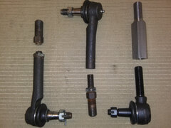
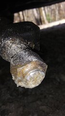
I found the kit to be a little "underwhelming" as well when I saw the installation on Elvis, the 1947 DeSoto I've been working on. On Elvis, the taper on the outer tie rod ends looks small for the steering arms. I'm not sure if that happens on every car this kit fits, but ours, the nut goes so far down the threads that the cotter pin doesn't engage the castle nut, and the nut is free to turn and loosen, although it shouldn't come off because the cotter pin is at least blocking it from coming entirely off. I had reservations about this kit from seeing that. Then, our driver hit a pot hole at about 20-25mph, and this happened: Here's a close up of the failed coupler from the kit: We were lucky. The failure happened at relative low speed. The only damage, other than the failed coupler was a bent wheel. It also happened a couple hundred yards from the trailer he was about to load the car onto, so there wasn't even a towing issue involved. He did regret not buying the optional winch on his trailer, and we're looking at adding a winch to it now. Back to Elvis, I have already installed more correct outer tie rods, and I had a local machine shop turn out a pair of new adjusters/couplers for the tie rods. This pic shows the old ones (both the failed one and the one that hasn't failed yet), beside the new outer tie rod ends and the new adjusters. If anyone else wants to do this upgrade to their setup, David Carlisi at Linkage Solutions in Cumming Georgia made our new adjusters. They weren't cheap. He'll do a pair of them in 303 Stainless (that's what we got) for $380. A pair in 1018 mild steel will be $330 or $340 he said. The cost of a failure at highway speed could be much higher, and could include injuries. As I said, we were very lucky this happened at only 20-25mph on our car. The outer tie rod ends are Napa part number ES60R (Made in China, but available quickly). If you want higher quality parts, RockAuto has Delphi TA5398 or Moog ES158R listed for these applications. I think the Moog and Delphi ones use a larger castle nut and aren't stepped down on that end. When our Napa outer ends wear, we'll likely go to the Moog part for the replacement. Oh, and you'll also need Jam nuts for the outer tie rod shaft. SpeedwayMotors had them in stainless steel for $4.99 each. That's where we're getting ours. They're on the way and should be here Monday. Here's a gallery with more pix of the failed parts and a few pics of our new upgraded replacement parts.
-
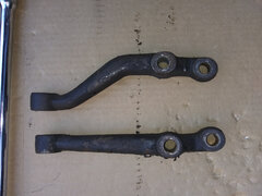
I had a very busy day yesterday. It started with picking up some parts from the machine shop to repair the damage shown in the (original) opening post on this thread. Here's one quick picture showing the failed parts (left), the parts from the other side of the car, from the "Rack and Pinion conversion kit" that haven't failed (yet), and the parts I'm installing to replace the failed parts and the parts on the side that hasn't failed yet. I've added an album of images for this. There are more pix at Moving on to today's mystery, it's the steering arms. I'm also adding this to the opening post and changing the title on this to reflect my new questions. Steering arms. WTH happened here? Here are the steering arms removed from this car: The one on top was installed on the right side, the one on the bottom was on the left side. More pix are in a gallery here: This looks like a repair that might've been done while the car was in Cuba. They did have a tendency to use whatever parts they had available to get their cars back on the road. I seriously doubt the factory put one outer tie rod end on top of the steering arm (left side) and one below (right side). There are part numbers on both arms. You might be able to make out the numbers on the straight (left side) one in the pix. The next time I go back to work on this one, I'm bringing paper and charcoal pencil to try to "lift" the numbers in a readable form. My biggest question is, what steering arms should be on this car? What were the originals? And with the rack and pinion conversion, are there shorter arms available for alternate applications that will bolt on and work better. The car owner has already asked, "Can your guy at Linkage Solutions make us some matching new arms? Maybe even some that are shorter, to make the turning circle smaller?" and I think the answer to that is probably, "$ure he can." I'll have to call him Monday. OTOH, if there's something available that will work and is from a vehicle in the same weight range, I'd rather use that.
-
From the album: Elvis's mystery steering arms
These are the two steering arms show from the bottom side. The one on top of the pic is from the right side of the car, the one on the bottom of the pic is from the left side of the car. -
From the album: Elvis's mystery steering arms
Side view of the two steering arms. The top one was installed on the right front. The bottom one was installed on the left front. I'm not sure which is correct for the 1947 DeSoto Custom Sedan, and I'm actually thinking that both of these are supposed to be right side steering arms, and the one installed on the left was just flipped over. -
From the album: Elvis's mystery steering arms
This pic shows the left side steering arm. This one looks very wrong. It's straight (not the biggest issue), and the taper is such that the outer tie rod end must be installed with the joint on top, the castle nut on the bottom. I really don't like the geometry and clearance with this setup. It really looks to me like this is another right side arm that's been installed on the left side of the car. Possibly this was a "repair" done when the car was in Cuba, using the only part they had available to them. -
From the album: Elvis's mystery steering arms
This is the steering arm on the right front wheel of the car. This one has an upward "s" bend in it, and the tie rod end sits below the arm, with the castle nut on top. -
From the album: Elvis's Tie Rod Failure
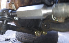
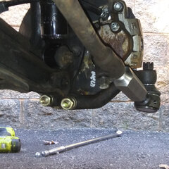
Well, more like "test fitted." I'm still waiting on the jam nuts to arrive. -
From the album: Elvis's Tie Rod Failure
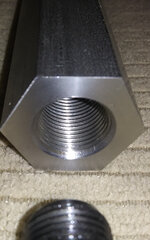
Closeup of the outer end of our new parts. This shows the female 11/16-18 threads which match the new larger outer tie rod end we installing. Our new adjusters/couplers were made for us by Linkage Solutions in Cumming Georgia. -

New part from Linkage Solutions machine shop, Cumming GA
Racer-X- posted a gallery image in Mechanical
From the album: Elvis's Tie Rod Failure
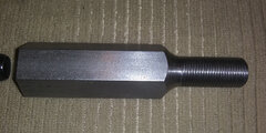
This is the new part. The male threads are M22x1.5 left hand threads and match the inner tie rod ends from the GM rack used by the kit. The outer hex section is 1-1/8" on the hex (uses that wrench size), and is drilled and tapped for 11/16-18 right hand threads to match the new outer tie rod ends that are appropriate for the 1947 DeSoto Custom Sedan (and many other early Mopar cars). -
From the album: Elvis's Tie Rod Failure
This is the original part from the conversion kit. The top section in this pic is the M14 section that matches the outer tie rod. This is the end of the part that failed when our driver hit a big pot hole. Clearly that section isn't adequate for the forces present in the steering on our heavier cars. -
From the album: Elvis's Tie Rod Failure
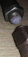
Close up of the point of failure on the "tie rod coupler" from the rack and pinion conversion kit. My metallurgy experts say this looks like a tension overload failure. The part was literally pulled apart from the forces when the tire hit a big pot hole. -
From the album: Elvis's Tie Rod Failure
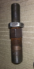
On the left, a broken tie rod couple and outer tie rod from a "Rack and Pinion swap kit" that "is designed to work with 1930s to '50s Mopar applications ... In the center are the unbroken parts used by that "conversion kit, the outer tie rod is for a Ford Explorer (yikes!), and the coupler is "custom made" from the kit. At the right are the replacement parts I'm installing after the failure. The outer tie rod is correct(ish) for a 1947 DeSoto Custom Sedan, and the coupler/adjuster piece I had made at a local (to me) machine shop. -
Is there an online source for those numbers? I've been looking (in truth, not very hard yet) for that info for our 1947 DeSoto Custom Sedan. Awesome thread. I'll probably post over on that one as it seems like the kit discussed there (including this post from back in March) is what was installed in this car. It looks like we'll pay more for the stronger tie rod adjusters/couplers than the entire kit originally sold for. There was an email from the machine shop when I signed in this morning. Looks like he worked late last night on this "rush job," and he has the new parts ready to pick up already. That's also awesome! Makes me a bit sorry I asked for a reprieve on getting Elvis on the road by this evening, and blamed it on last week's driver. I might've been able to make it. Welll, maybe not really. I just checked and the jam nuts for the new tie rods are still on schedule for delivery by USPS mail tomorrow (Saturday) or Monday.
-
I'm really not sure that's an option on this one. This car has a long history of "work arounds" and modifications. It lived most of its life in Cuba. There's definitely some Cuban repairs evident on it, with parts substitutions and "home made" parts used in some repairs. Then it was brought to the USA and spent some time in a Cuban owned custom shop in Miami. There it got a beautiful (looking) interior, a LS1 swap (allegedly from a Corvette, which might be true, but the engine itself has some significant modifications), a 4L60E transmission, new 12V electrical system, Air Conditioning, this rack and pinion conversion and some other stuff. The best thing I can say about the work done in Miami is those guys really knew their stuff with Upholstery and interior trim. That part looks beautiful. The wiring looks like it was done by an Upholstery and Interior craftsman. The fuel system and engine wiring looks like it was done by an Upholstery and Interior craftsman. At some point either the shop in Miami, or the owner who took this car there (the story isn't really clear) ran out of money and/or talent and sold this incomplete "project car" off. It was bought by some folks in North Georgia. They had a couple of mechanics working on the thing. One is no longer available, out on I believe 10 years leave of absence, unless that gets shortened for good behavior. The other guy was a personal friend of the owner's who I refer to as "Bubba's brakes and mufflers." He did the brakes and exhaust, and it would've been better and much easier if I started with nothing than it is repairing and redoing his work. The brakes are another huge mess on this one, worthy of their own thread. It's an unusual situation. The interior must be kept immaculate. The only interior mod possibly on the horizon is rear seat air conditioning. Rear seat passenger comfort and luxury are top priority. Safety and reliability are also very high priorities. "Restoration" to original specs isn't even on the list of necessities or even the "nice to have" list. Driver comfort and driver information is low priority. Some of the gauges don't work, but according to the owner, none of his "antiques" have working speedometers or fuel gauges, so that's to be looked at only when everything else is done. As for the steering, I don't have the original steering unit. I don't have the center idler arm. I don't have any of the original steering stuff. The engine mounts and the exhaust headers are filling a lot of the space where the stock steering gear was originally located. Even if I could source something that would work, it probably wouldn't fit in the car now. The "conversion" rack barely fits in there with the exhaust. It only clears the exhaust header collector by about a quarter inch. Right now, I've been talking with Turn One Steering up in Saginaw about the rack, the pump, and the fact that we'll be adding a hydroboost power brake booster to the system, along with a new (different) master cylinder. The folks I've been talking to there seem to think the rack we have will be adequate, although it may need to go to them for a rebuild and some modifications. I'm actually picking up another rack core to send them for that. We're almost certain to need an upgraded pump. The question on that is whether something from an application like a Chevy Express Van (which had hydroboost brakes and power steering and when fully loaded down was closer to the weight of this car), or if we'll need one of their modified "high performance" units. Enough rant. @Bryan, that looks like a pretty good setup on that Dakota. I do agree with you about using new (ish) parts, and keeping the entire fluid circuit fresh and clean. The current rack in ours looks like an untouched junkyard unit. The power steering pump (and all the belt driven accessories on this thing) look like they came from some Chevy truck, again, they look mostly like junkyard pulls. I'm definitely going with new or rebuilt units for all of that over the winter when we upgrade the brakes. And I'll keep this thing a lot cleaner when putting it back together. And @Andydodge, your setup looks really good. It looks like you have a very well sorted old school "resto-mod" there that's built well and has already lived and driven long enough to be an antique in its own right. I can only hope that I can build something that will last as long as yours has.
-
From the album: Elvis's Tie Rod Failure
-
From the album: Elvis's Tie Rod Failure
-
From the album: Elvis's Tie Rod Failure
-
I just found this today. I wish I had known sooner. I'm pretty sure I can't get away this weekend.
-
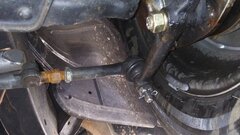
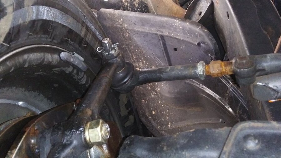
Here's a pic of the side that didn't fail (yet). Also noteworthy in this pic, the tie rod end is attached to the steering arm with the nut on the bottom and the joint on top. The right side had the joint under the arm with the nut on top. I think this side is installed "upside down" at the outer end. And, yes, that's brake fluid on the inside of the wheel. That leak at the caliper is being addressed as well. This one also has a very poorly made and poorly installed "disk brake conversion" as well. More on that once we get the steering sorted out and safe.
-
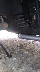
UPDATE: 11-20-2021 Yesterday, I went to work on this car, to test fit and check the new outer tie rod ends and tie rod adjusters/couplers. That's when I found this: Steering arms. WTH happened here? Here are the steering arms after I removed them from this car: The one on top was installed on the right side, the one on the bottom was on the left side. More pix are in a gallery here: This looks like a repair that might've been done while the car was in Cuba. They did have a tendency to use whatever parts they had available to get their cars back on the road. I seriously doubt the factory put one outer tie rod end on top of the steering arm (left side) and one below (right side). There are part numbers on both arms. You might be able to make out the numbers on the straight (left side) one in the pix. The next time I go back to work on this one, I'm bringing paper and charcoal pencil to try to "lift" the numbers in a readable form. My biggest question is, what steering arms should be on this car? What were the originals? And with the rack and pinion conversion, are there shorter arms available for alternate applications that will bolt on and work better. The car owner has already asked, "Can your guy at Linkage Solutions make us some matching new arms? Maybe even some that are shorter, to make the turning circle smaller?" and I think the answer to that is probably, "$ure he can." I'll have to call him Monday. OTOH, if there's something available that will work and is from a vehicle in the same weight range, I'd rather use that. From before: Elvis, my latest project, is a 1947 DeSoto Custom Sedan with numerous mods (notably including a LS1 engine, 4L60E transmission). One of the mods done by the previous owner/builder was a "rack and pinion conversion." They bought a "kit" that included mounts for a 1990+/- a few years GM rack (J body and N body applications), and some couplers/adjusters to attach the inner tie rods from that rack to outer tie rods for a 2004-2005 Ford Explorer. Looking at the car while resolving other pressing issues (especially in the braking system, more on that in another post soon), I really didn't like the looks of the outer tie rods. The taper is too small for the steering arm on the DeSoto suspension/steering, and the castle nut was tightened so far down the thing that the cotter pin didn't engage the slots in the top of the castle nut at all. The cotter pin would've prevented the nut from backing off entirely (unless the cotter pin broke), but it wasn't preventing the nut from turning. The threaded adjuster rod also looked small for this application. The inner male threaded part was M22x1.5 (with left-hand threading), and looked strong enough. The outer part was M14x1.0 I think, definitely M14. Well, the car was ready to drive, and drove last Saturday evening. The driver hit a pothole, and the threaded tie rod adjuster rod snapped (failed, fractured, separated) on the narrow (14mm) end. We were very lucky, the only damage to the car was a slightly bent wheel and the broken tie rod adjuster piece. Has anyone else used a rack-and-pinion conversion similar to this one? Is there a better alternative out there? Right now, the failed part, and the unbroken example from the other side are at a good machine shop, and the estimate is $350+ to make two new tie rod adjusters that match the GM rack inner tie rods, but use the original/stock outer tie rod ends with 11/16-18 male threads on the outer tie rod end. The design is significantly beefier. He's proposing 1-1/8" hex stock, turned down and threaded M22x1.5 left hand male threads on the inner end, and drilled and tapped on the outer end for 11/16-18 right hand female threads to use with a right hand male threaded original tie rod. We're strongly leaning toward doing this as the car has to drive again next weekend. I'm looking for any other ideas, and also kind of curious if anyone else is using the Ford Explorer outer tie rod ends and would be interested in upgrading to the larger ones we're considering before they experience the same failure. Here's a pic of the failed part. It looks like there's a 3M limit for pix, so I'll have to post more pix as replies.


