


Mertz
-
Posts
399 -
Joined
-
Last visited
Content Type
Links Directory
Profiles
Articles
Forums
Downloads
Store
Gallery
Blogs
Events
Everything posted by Mertz
-
Good point I did hear that type of noise when I turned the engine off. It lasted quite a while but didn’t find the source. All new wires and it starts and runs fine.
-
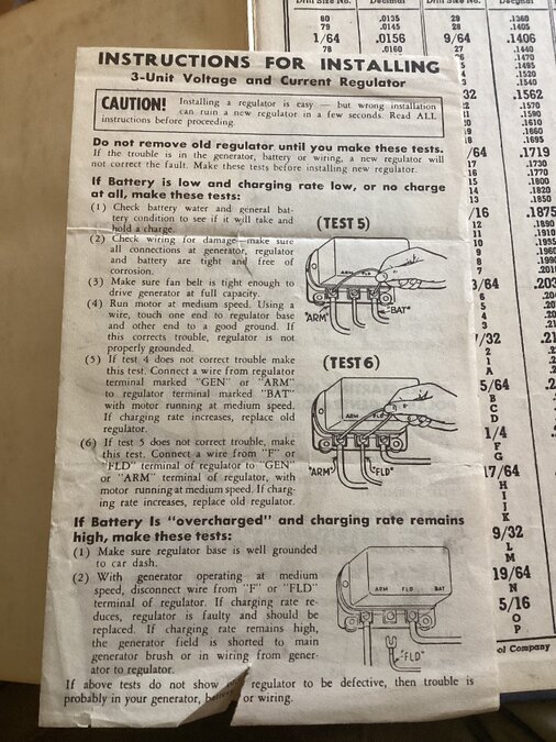
I took the cover off the voltage regulator and didn’t see any movement in the contacts and the generator got very hot. There was a steady magnetic pull on all coils. The volt meter went crazy with only one lead connected to bat and gen. I believe the fault is in the regulator. Is this supposed to be an autolite regulator? What should the amperage be? I can get a VRR-4003A on line. Would that work? What is the correct unit for my truck?
-
I found these instructions for a new voltage regulator tucked in my motors manual which seems to contradict the removal of the field from the regulator.
-
1940 Plymouth PT105. I have a manual but obviously not as complete as yours. I’ve been trying to get a good picture and will submit when I get one. I’ll check Rockauto.
-
Tests showed no charge at high idle for both tests. Can you send page 84 to test the VR? It is a new 6v unit but might not be the right one. I was just ready about test my VR and it appears the body of the VR needs to be grounded. Mine is attached to a board mounted to the firewall because the bolt pattern of the regulator didn’t match the holes in the firewall. I’ll try grounding it. Grounded it and it slowed down a little but still going over 20v. Flashing on all settings on two different meters.
-
I’ll do these tests and let you know. Did the same thing on AC setting. I did polarize at the regulator to make sure it was polarized. If I had a battery in my Studebaker I would see if it does the same thing when running.
-
That terminal was already off when I got the truck. The wiring diagram I have doesn’t show the terminals as they actually are on the switch. It shows 4 and only three used. Pretty hard to tell the color after 84 years. The loose wire is, as I stated, the one at the top of the picture in the link that was posted in this thread.
-
I sprayed electrical cleaner in mine but it didn’t help. I have one lug that has come off. It is the one furthest to the top in the picture in the link. Does anyone know what that feeds? I assume it’s the running lights because everything else is working and I used the running lights for my turn signals so they are not connected to the switch anyway. Also I can’t get the connection loose. I’m afraid if I try to remove the wires on my switch I will break something.
-
Yes the location is the other issue. I’m not sure how to find it for the exact location.
-
Good point about the AC setting. Battery is good but I will try other meters I have.
-
I checked the terminals on the battery, 2 terminals on the generator, battery to both other terminals on the voltage regulator. I thought maybe it was the voltage regulator kicking on and off but am not sure. Since there is no over voltage at the lights I thought that might be the issue. It was blinking very fast and hard to read.
-
It reads perfectly with the engine off. I’ve been using it for a couple of weeks now on other issues like checking wire connections with the ohm meter and checking voltage to gauges. I will try another meter that is brand new.
-
I checked the voltage on my battery and it reads 6.39v. I’ve been playing with various electrical issues so I slow charged the battery overnight. I decided to checked the voltage while the engine is running. The amp meter is centered at idle and moves quite a bit to charge when accelerating. Generator rebuilt with new bearing and brushes. New voltage regulator. When set to 20v on the volt meter I was getting a flashing 19 so I moved it up one notch and same reading. Moved it up to 1000v got the same flashing reading. Checked the voltage at the generator and voltage regulator and got the same thing. Put the engine on high idle and turned on the headlights hoping they would not burn out. They didn’t and were just as bright when I turned off the engine. Is this just the voltage regulator working, turning on and off the charge?
-
Thanks for the input. I know what you are saying is absolutely correct and I may still get the correct sender. The sender I have is a 73-10 ohm. It’s the TAN-ORG unit. They knew exactly how to install it on my gauge with the same instructions as DCM so it has been done before. I told Tanks Inc what gauge I have. The only thing my repair manual has concerning the fuel gauge is on the wiring diagram. I don’t like the overall result but it is working. If I had easy access to the sender I would change it in a heartbeat.
-
This is 73-10 ohm universal sending unit. It is working although very slowly. I got a reading of between 1/8 and 1/4 which according to Tanks Inc is a bought right for the 51 ohms reading I got from the sending unit. It got to about 1/4 then dropped back down to 1/8. if I had to pull the tank I would have definitely cut a hole for access. Cutting it with the tank in place is a little too risky for me. I would be using a hole saw and the pilot drill would hit the tank. I did find a correct sending unit on eBay sold by Andy B for a very good price but since it’s working I opted not to by it. Again. Thanks everyone for your help.
-
Talked to Tanks Inc and they told me to ground the sensor at the ground wire then hook up the sensor to one of the other wires. One should provide a reading. It did but it was hard to see much movement since it went just to empty with 1/4 tank of fuel. I guess it’s working but I’ll add more gas and see if I get a better reading. I might have not installed the sending unit just right. Thanks all for the help.
-
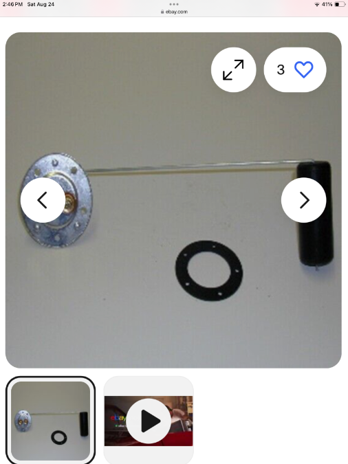
I have mud on my face. I assumed that the sending unit bolt pattern was the same as the inspection cover plate pattern. It actually does have five holes. The sending unit is still wrong and I sent the supplier a picture of mine plus a diagram from a motors manual on how the sender works and how it is wired. They say their unit will work for my year truck but they don’t say only if it has the right gauge.
-
I tried it but it didn’t work. That terminal is already a ground and grounded to the tank. I was hoping. I’ll let you know what supplier has to say. It is clearly not the correct tank or sending unit.
-
I have written the company and will see what they do. I can live with the adapter. I hope that they will provide both the adapter and the correct sending unit. I recently installed the bed on the truck so tank removal will be a little more difficult.
-
When I bought the unit it said it was correct for my truck. I probably should have done more research to make sure it would fit. The tank fits fine. I did tell the supplier that this forum said it was the wrong sending unit but they insisted it was correct for my truck. I will try to get some help from them but I’m not confident it will work. I will see if I can gat the adapter and new sending unit. Thanks everyone for the help on this. It’s a great forum and I could not have done what I have on the truck without you. Hopefully on the road soon.
-
I understand that thermal gauges are unusual. Here is what I bought.

-
All those sending units are 5 holes and my tank is 6 holes. Yes this is apparently a thermal unit. Will a later gauge fit in my dashboard? Maybe I can hide a working unit in the glove box and keep the old one for originality. I was sold a tank and sending unit specific for my truck.
-
My sending unit doesn’t look like the OEM unit. It has an adjustment for a deep tank and shallow tank. First pic is the unit I bought with the supposed correct sending unit. The unit I bought with the tank has 6 screws while the OEM has 5 screws

-
I did run a jumper from the mounting screw on the sender to a good ground. Mine has two wires from the sender but 3 on the gauge one being power from the ignition switch which I confirmed with the wiring diagram. This gauge apparently is a two sided gauge with one side counter acting the other side.
-
Checked the ground at the sending unit and it’s good. Added a jumper from ground to the sending unit and tested again. Good ground. Grounded the sending unit terminal and the gauge goes to full. Grounded the ground terminal on the gauge to the battery. Power to the gauge. There was one point where it didn’t go completely to full but and fluctuated near full.