-
Posts
892 -
Joined
-
Last visited
-
Days Won
2
Content Type
Links Directory
Profiles
Articles
Forums
Downloads
Store
Gallery
Blogs
Events
Everything posted by harmony
-
.thumb.jpg.d599d4c13e08899474e0348bd9baed3b.jpg)
New question regarding firing up my 251 on the run engine stand.
harmony replied to harmony's topic in P15-D24 Forum
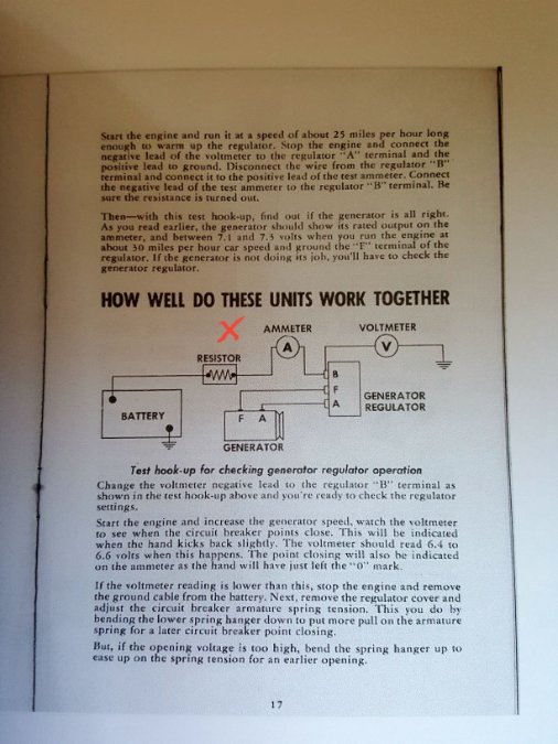
I have a half a dozen of those gizmos I think. I get tired of trying to find the one I lost in my shop so I go buy another. Then one day I seem to spot 4 of them, by tripping over them. Then the next day I can't find one, so I go buy another one,,,, and on and on it goes. I was thinking about your suggestion, when I came across the illustration in the "service reference book" that I mentioned before, that shows the resistor ( see x in the illustration). The volt meter is wired in after the ammeter at the B terminal on the regulator. At that point I was thinking, "why not use a multimeter? Then the whole idea slipped my mind until you just mentioned it. Getting old is such a fun journey,,, hahahaha! -
.thumb.jpg.d599d4c13e08899474e0348bd9baed3b.jpg)
New question regarding firing up my 251 on the run engine stand.
harmony replied to harmony's topic in P15-D24 Forum
I'm not sure if I did this right Sniper. But here is that film clip. It's mentioned around the 15:30 mark. -
.thumb.jpg.d599d4c13e08899474e0348bd9baed3b.jpg)
New question regarding firing up my 251 on the run engine stand.
harmony replied to harmony's topic in P15-D24 Forum
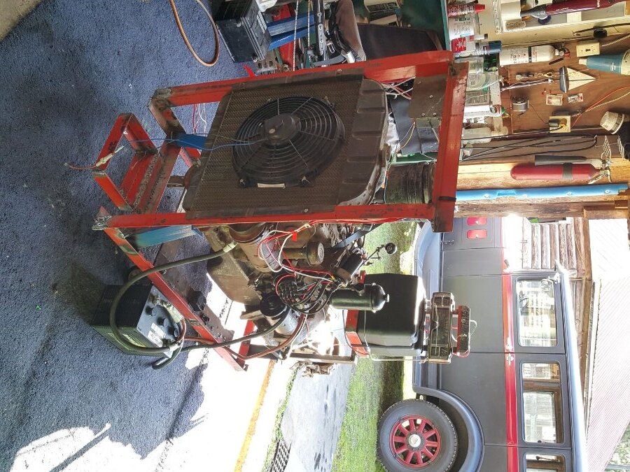
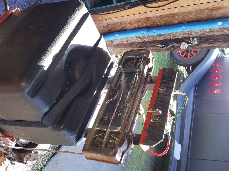
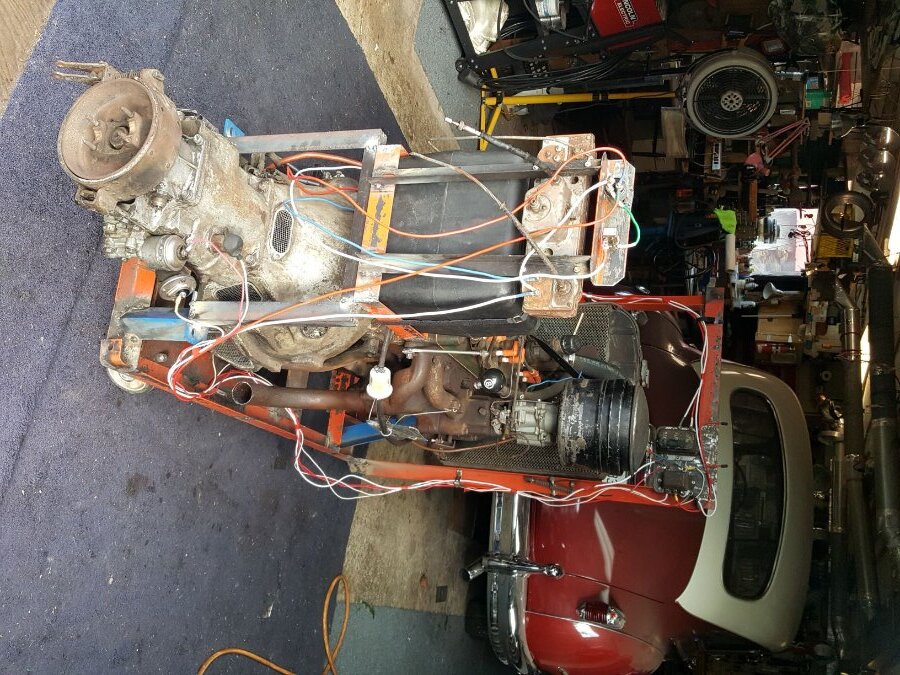
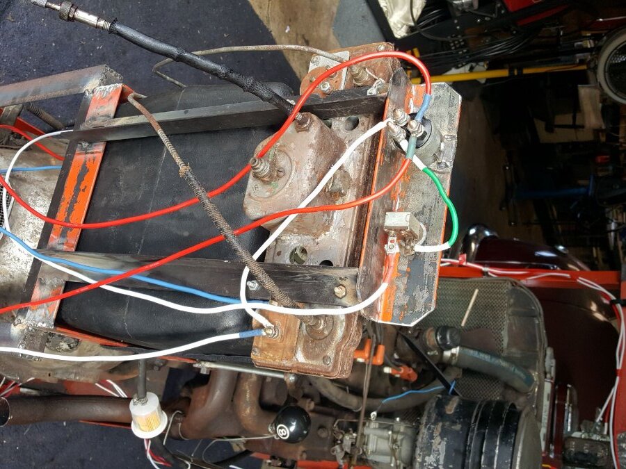
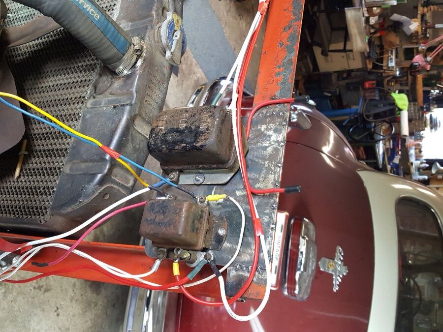
D35 Torpedo: That's exactly what I was thinking. If all the accessories (so to say) are turned off, then it's basically the same set up as I have. greg g & Sam Buchanan. I agree, I've always felt more comfortable looking down at the instruments and seeing a volt meter as opposed to an ammeter. However,,,, This '46 was equipped with an ammeter. I don't happen to have a volt meter kicking around the shop. Plus I've wired in the original instrument panel, which makes economic sense to me. As I've mentioned before I'm pretty thick headed when it comes to auto electrics so I don't really see the difference between what I've set up and the way it was when the engine, fluid drive and transmission were operating in the car, except for a bunch of body steel surrounding what I have here. But when "Master Tech" said the ammeter would basically blow up without a load on it, I got confused, which is why I've enquired here. I've added a few pictures of my set up,,,,, and yes,,,,, the wiring will be tidied up in a loom once I'm finished. Yes,,,,, I've only got a few different wire colours, but I didn't want to spend about $120 plus, just so I could have a rainbow of colours. Instead, I used different colours of heat shrink on the #10 wire ends that I did have, to tell them apart. Yes,,,,, the battery is on the floor and not in the battery box that I built for it. That's because I borrowed it from my '48 Chrysler. I'll buy a designated battery for it once I getting it running. Yes,,,,, I have two battery leads for the negative side of the battery. That's because I didn't have enough 0/0 cable to run both positive and negative. But I did have a couple of long 12 volt cables (4/0) so I just doubled up on the negative side of the battery. Finally, yes,,,,, if this project is a success, I'll give the framework a coat of paint so it's all one colour. Once again, as in the past, I'm sorry for giving everyone a stiff neck, but I'm not about to keep altering the dimensions of regularly shot, run of the mill pictures taken from my run of the mill phone, just so they won't show up laying on their side on this forum, which seems to happen more often than not, at least for me. -
I've sorted out most of my issues thanks to you guys. I've got my 251 with fluid drive all wired up and everything sort of checks out. I can hit the start button and the engine turns over and I have spark to the plugs. I've also polarized the regulator. Basically all I have to do is add some fuel. I've filled the cooling system and no leaks there. But I'm trying to cross all my "T's" and dot all my "I's" and make sure I've got it right. I was re-watching an old "Master-Tech film clip "1948 Volume 1-6 Volts Amps and Ohms". Something was said in that film clip caught my attention. Remember I'm just running the essentials on this run engine stand. Well a little more than essentials because I want to test all the circuits. So I've wired in the Regulator, Trans Relay, Governor switch, Trans Solenoid switch and the Interrupter switch. But normally, as in the complete wiring diagram, coming off the Ammeter you have a wire going to the cigar lighter, and another wire going to the light switch. Also on the ignition switch on the one post you have a wire going to the back up light, turn signal flasher, horn relay, and the fuel gauge. So that's a total of 6 wires that I'm not running, because I don't have any of those items. So in the Master-Tech film clip they say when doing a test "An ammeter has very little resistance, so if you connect it so it carries the full battery current itself without any resistance, it will burn out instantly". To add to that though, I was reading the "Service Reference Book" Vol 1 No.7 " reference to the Generator Regulator", and on page 17 there is an illustration of a test being performed and it shows a resistor on one side of the ammeter. " So my question is, since I'm not running any accessories (those 6 wires), do I need to protect the ammeter with a resistor?
-
That's an interesting point that I never considered, about the draw. There is actually an inline fuse on the load wire of the fan now with a 25 amp fuse in it. It came that way when I stumbled across the fan a years ago The information decal on the fan is not readable anymore so I'm not sure what it is rated at. With what you just said, maybe perhaps I should go with a 110V fan set up. The plastic electric 12 volt fan sort of looks out of place attached to the radiator of a flathead engine anyways.
-
In my second paragraph, I've mentioned the wiring coming off the ignition switch in the wiring diagram. Which is in the service manual, which is well used as the dirty pages will indicate. There is no mention in the manual as to the actual ignition switch, and no mention of which post is which on that switch. The posts do form a pattern of a triangle when illustrated, that "could" match the orientation of the actual switch. When operating the key and using a multi-meter, I do get continuity that supports the flow of current to indicate that the wires would be going to the switch such as I indicated in the first paragraph. I'm hoping to get confirmation on that ( i.e. my thoughts on bypassing the fuel gauge) as well as learn what RAD and GA mean, which is not mentioned in the service manual.
-
My mistake for say "Just reversing wiring so to say" I was just trying to emphasize that the wires on the fan were going to the opposite battery posts. I'm not reversing the fan leads. That would make the fan a puller, not a pusher. The load wire (positive)on the fan, is going to the ground post of the battery. The ground wire on the fan is going to the load side of the battery where all the components of the electrical system are getting their power from. Will that confuse the fan motor? As in start to smoke. Or will it confuse one of the electrical components on the engine causing it to smoke? The fan is plastic and it's attached to the radiator with plastic snap ties. So it's not finding ground through the engine. Only through the battery. If that is any consolation. I was kind of surprised at how fast the fan actually goes when hooked up to a 6 volt battery. Another alternative would be that the engine run stand likely to be within the length of a 100 ft. extension cord away from 110 AC volt outlet, whenever I'm running the engine. Or I do have a relatively quiet Honda 2000 generator. So I could set up a floor model 110 volt fan in front of the radiator.
-
My objective is to wire it completely as it would be as if it was in a car, and check all the circuits and make sure it's all functional. I haven't quite figured out how I'll operate the fluid drive and shift the gears, just yet. Not many people besides the post war Mopar enthusiasts are familiar with the process of all the functions of all the components that make up the entire package that makes the car go down the road. I think that Chrysler post war technology is pretty complex for its time, the way the Governor, Transmission Solenoid, and Interrupter Switch perform their duties in conjunction with the Trans Relay, and how the electrical side of the Carburetor plays a part in all that. I also have my 1930 Hudson flathead straight eight engine and transmission, that I intend to do the same to. The run engine stand is built for that and I'm just keeping an eye open for a reasonably priced vintage radiator for it. That engine was rebuilt in 2004, but hasn't been fired up since then, so that should be an interesting project once I'm done playing with this 251. The car club that I'm a member of is trying to encourage me to have them both up and running and on display at our annual car show this August. I guess I'd better line up a couple mufflers as well.
-
Well in a sense they do, according to my electrically brain dead mind. They share the battery. Just reversed wiring so to say.
-
Haha! The next project is already waiting for me. I have also built another run engine stand for my 1930 Hudson straight 8, patiently waiting for me, to see if I can get it running. I just need a radiator for it. Plus do all the wiring. Won't that be fun. !!
-
How do you mean "isolated" Sniper?
-
I'm about to wire in the ignition switch for my run engine stand. (1946 Chrysler) I have the original start button and ignition switch. One side of the start button will go to the small post on the starter solenoid. (The post right above the battery lead terminal) That much I know. I'll mention the other side of the start button switch at the end. The ignition switch has 3 posts. ( one long and 2 shorter ones) The tall one has two markings beside it. RAD & GA. One short post has COIL marked beside it and the other short one has AM marked beside it. I suspect a wire will go from the AM post on the ignition switch to the Ammeter, right? I also suspect a wire will go from the negative side of the coil to the ignition switch post marked COIL. Right? So this leaves the long post. I'm just wiring up the engine, and fluid drive, nothing else. So that included the generator, starter solenoid, regulator, trans relay, governor, interrupter switch, solenoid (on transmission), kickdown and anti-stall on the carb. According to the wiring diagram, coming off that long post on the ignition switch is a wire going to back up light (Doesn't apply). A wire going to the turn signal assembly (doesn't apply). A wire going to the horn relay ( doesn't apply). A wire going to the fuel gauge ( doesn't apply). However when I follow the other wire coming off the start button ( as opposed to the wire I mentioned at the beginning) it goes to the fuel gauge and then back to the ignition switch. In the diagram it looks like it's going to the long post. Since I'm not connecting the fuel gauge to a tank, should I run the wire from the start button directly to the long post on the ignition switch? I'm using the entire stock gauge cluster on my run engine stand, so I could run wires through the fuel gauge if necessary, but it's not connected to a sender unit, since I'm not using a conventional gas tank, so it seems unnecessary to me. Btw, what does RAD & GA mean?
-
Certainly easy, you're right. I just don't have a spare 12 volt battery, and I built the mobile ( on wheels) engine stand to accommodate only one battery.
-
The case of the fan is all plastic. I have it fastened to the radiator through the core with plastic zap-straps. Yes two wires coming off the fan motor.
-
I've built a run engine stand for my spare 251 flathead. I had one of those plastic radiator fans kicking around, so I thought why not add more air flow, so I mounted it on the outside of the fan since it is a pusher fan. But it's 12 volt and I'm running a 6 volt battery. No big deal, it still operates, just turns a little slower. However, as you all know my engine is positive ground. The fan is negative ground. If I reverse the wires on the fan ( positive to ground) it runs in reverse and turns it into a puller fan. Defeating the purpose. Ok, so here's my stupid question of the day. What will happen if I run the fan, negative to ground, while everything else is positive to ground? Will there be an explosion or a melt down? If so, is there a way around this?
-
.thumb.jpg.d599d4c13e08899474e0348bd9baed3b.jpg)
1946 Chrysler starter questions, more help needed please!!
harmony replied to harmony's topic in P15-D24 Forum
I got the solenoid cover back on and the starter mounted in place. Since I don't have a wealth of knowledge on wiring, I'm going to wire everything on the run engine stand as it would be on the car. I added up all the wiring and it comes to 53 feet. I'm thinking maybe #14 would be big enough. Or should I be going to #12 for some of it? -
.thumb.jpg.d599d4c13e08899474e0348bd9baed3b.jpg)
1946 Chrysler starter questions, more help needed please!!
harmony replied to harmony's topic in P15-D24 Forum
Thanks for that reminder about that square stud on the end of the plunger being able to be adjusted. I remember reading about that in the manual. Yes I did get those small side brackets hammered back into original shape. I'm just going to stick with the allan machine screws that were being used. I'm doubting I'll be taking it to Pebble Beach to be judged anytime soon. Thanks for that illustration. -
.thumb.jpg.d599d4c13e08899474e0348bd9baed3b.jpg)
1946 Chrysler starter questions, more help needed please!!
harmony replied to harmony's topic in P15-D24 Forum
Looks like it does need to go to ground when doing a bench test. But only then. But the manual doesn't mention that. -
.thumb.jpg.d599d4c13e08899474e0348bd9baed3b.jpg)
1946 Chrysler starter questions, more help needed please!!
harmony replied to harmony's topic in P15-D24 Forum
I guess I'll just install it and see what happens -
.thumb.jpg.d599d4c13e08899474e0348bd9baed3b.jpg)
1946 Chrysler starter questions, more help needed please!!
harmony replied to harmony's topic in P15-D24 Forum
Ohhh ok. -
.thumb.jpg.d599d4c13e08899474e0348bd9baed3b.jpg)
1946 Chrysler starter questions, more help needed please!!
harmony replied to harmony's topic in P15-D24 Forum
I'm confused. Because the wiring on my daily driver '48 is the same. I have one wire going from that small post that I just grounded, to the A post on the generator. No ground wire. From what you just said, I'm reading that it's ok for me to permanently leave a wire going from that small post to both ground and the A terminal on the generator? -
.thumb.jpg.d599d4c13e08899474e0348bd9baed3b.jpg)
1946 Chrysler starter questions, more help needed please!!
harmony replied to harmony's topic in P15-D24 Forum
After reading the manual again. It says that after performing that test you gave me, the problem is in the generator or ground circuit. Since the generator isn't connected, that leaves the ground circuit. I have The starter well grounded to the battery. As well as from the large solenoid ground post to the large starter post. I'm not sure where to check next. I guess I'll just start disassembling the solenoid and clean everything looking for anything odd. Then reassemble it. -
.thumb.jpg.d599d4c13e08899474e0348bd9baed3b.jpg)
1946 Chrysler starter questions, more help needed please!!
harmony replied to harmony's topic in P15-D24 Forum
I just tried what you suggested by grounding out the other small post directly to the battery. Then I pulled the trigger on the remote starter gizmo and the starter spins fine. So from what you said, it sounds like my coil is ok. But what should that be telling me as to what the issue is? According to my wiring diagram, when the starter is installed a wire goes from that small post to the A terminal on the generator. -
.thumb.jpg.d599d4c13e08899474e0348bd9baed3b.jpg)
1946 Chrysler starter questions, more help needed please!!
harmony replied to harmony's topic in P15-D24 Forum
Thanks, I'll try that tomorrow, I'm assuming it won't matter which terminal goes to positive or negative? So even though I have continuity at both wire ends of that coil, that sounds like it doesn't necessarily mean that the coil is good? If it proves to be bad, can I repair it, or does it have to be replaced? Oh, btw, when I apply 6 volts to those two terminals, does it matter if I'm connected with the battery leads as they are now? Or do I disconnect them before I apply power to the small terminals? -
.thumb.jpg.d599d4c13e08899474e0348bd9baed3b.jpg)
1946 Chrysler starter questions, more help needed please!!
harmony replied to harmony's topic in P15-D24 Forum
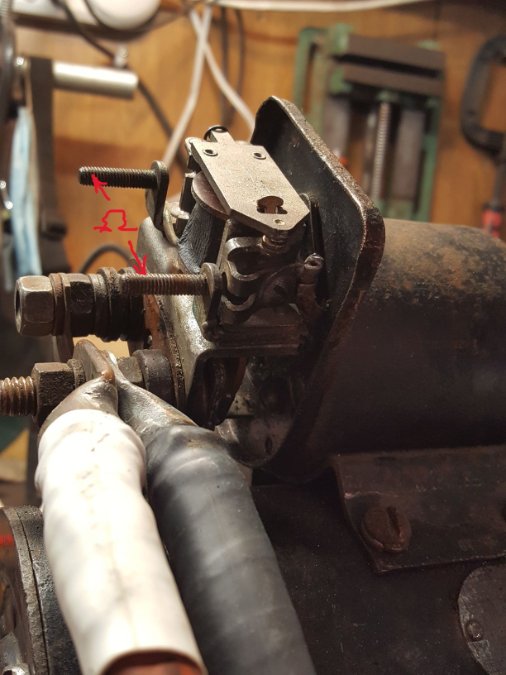
To answer MarcDeSoto's question, yes the starter works. It took several hours of almost rebuilding it. It was shorting out in multiple places and smoking like a hot rod doing a burnout. It also was turning over at a speed like it was -40F. But I'm thinking that might have been because I just grabbed a pair of 12V battery leads I had kicking around. So after beefing up the size of the cables, and cleaning the commutator, and resoldering a few sketchy wires, I've got it turning over to beat the band now. However,,,,,, As I've mentioned numerous times I'm dumb as a stick with electricity. So I can't figure out what I'm overlooking here. I've checked continuity in several places. So I have continuity between the two small posts, so that should tell me that my coil winding is good on the solenoid. The points were about 33th. Manual calls for 25-30 so I set them at 25 hoping that was the issue,,, nope. If I jump between the battery terminal on the solenoid to the small terminal, normally it would activate the solenoid and spin the motor. Nothing happens when I do that. I've used one of those remote start gadgets. ( It's in good working order and with the button depressed once the clips are attached from the large post to the small post, I have continuity there) I've even tried using a screwdriver to jump too. Not even a glimmer of a spark. But when I manually close the points with a screwdriver. The starter is off to the races. It spins really fast and quiet. I'm trying to comprehend the manual and I'm wonder if it has something to do with " Adjusting pinion clearance" I'm hoping not, because no matter how many times I read that, I don't get a picture in my head as to what it says. Also on the back( outside) of the solenoid is a screw, and somewhere I read that it is an adjusting screw, and yes as I turn it, I can see a plate on the inside of the solenoid move slightly. But I can't remember where I read that. Or what it's suppose to be adjusting. It doesn't even show that screw in the illustration in the manual ( or mention it on that illustration) nor does it show up in the parts catalog. I thought I had taken a picture of the screw, but I didn't. One of the pictures shows the plate that moves. ( red arrow with P ) and about where the screw is on the other side of the solenoid back plate ( red arrow with S ) Actually I just found that picture of the adjusting screw I'm talking about. (the last picture) Holy shomoly,, my memory is sooooo bad. I mentioned earlier in this very post where I read about that adjusting screw. So I'll go back and check out what "Master Tech" had to say about it. Now where the hell did I put my glasses...... Please talk down to me. Like I've never even heard the word electricity in my life before. I've been on this planet for more than 7 decades and no matter how many times people tell me ohms law is like water running through a hose, it's not sinking in, and I'm confident at this point it never will.


