

.jpg.70ad42aba0cfc865ed90fc3c3f5be0d5.jpg)
harmony
-
Posts
873 -
Joined
-
Last visited
-
Days Won
2
Content Type
Links Directory
Profiles
Articles
Forums
Downloads
Store
Gallery
Blogs
Events
Classifieds
Everything posted by harmony
-
Wow! Good to know about the plastic bottles. But now I'm curious about the "modern" plastic brake fluid reservoirs on the master cylinder? So at what % is the brake fluid unacceptable?
-
It's good to hear that you haven't had any issues with this pen. I was about to order one but then there were a few reviews that said they didn't trust them because they tried the tool in a brand new bottle of dot4 brake fluid and it read 4% water.
-
If you prefer the paper versions of the M5 transmission over the videos, here are a couple links about it. There are around 20 pages give or take in each booklet. https://www.web.imperialclub.info/Repair/Lit/Master/012A/cover.htm https://www.web.imperialclub.info/Repair/Lit/Master/012B/cover.htm
-
From the way you worded your post it sounds like you would like to go for a ride in another fluid drive car to experience how it's shifting and how the transmission sounds and responds. You probably already know this but the "master tech" videos cover the M5 really well. Also, perhaps you already know this, but the carb idle has to be as low as possible without stalling the engine. Around 450 rpm's. If it's higher than that, it just won't shift gears. But if you have a specific question, than there are a few of us that drive cars with that same M5 and are fairly familiar with what needs to be corrected in order for them to be reliable.
-
Yep, I know what you're talking about and I agree. You're doing a great job. Keep us informed with lots of picks to drool over as the project goes on.
-
Thanks for that link. I'm somewhat familiar with casting. I used to have a pressure pot and a vacuum tank for the purpose of woodturning projects. So I'm guessing that some of your dash pieces were fairly long. Did you make your own, long pressure pot or did you omit that part of the procedure?
-
Cool and very Interesting. It would be appreciated if you would explain the process in detail. I went to Grain it Technologies web site and although they do show some of the process in a video. They either have an issue with links to all the available videos on their web site, or they expect you to pay for their "info and selection" videos. Because nothing on their video page is linkable. The nice thing is that there are many patterns to choose from, even a number of leather patterns. I'm pretty sure that you wouldn't be boring any of us if you let us in on the process with tons of pictures throughout the process and or videos. I'd be interested in seeing exactly what tools you bought from them. Or did you buy the complete kit? Or perhaps the Pro kit? That roller is huge, so I'm guessing that you bought smaller rollers as well ( 7 sizes) in order to get into tight concave surfaces. I'm also curious what you needed from Smooth-On molds? Was that a separate process or was the mold making process incorporated into the graining process that you did?
-
I'm constantly looking for those bed frames on a front lawn with that beautiful sign that says FREE. I'm guessing that I have about half a dozen in my stock bin at any given time. I've built countless tools with those bedframe rails.
-
Thanks, Well at least you didn't say "stay clear of those skins". So at this point I just have to decide if I want to live with the scratched, slightly dinted in places, and tired chrome, hub caps that I have now, or dig deep into my wallett and bite the bullet. I'm guessing that the skin is already formed to fit over the edge of the hub cap, and once the adhesive is set, you'd gently start working your way around the edge to draw the lip in tight. Do you remember what you found to be the best tool for the job? I'm thinking a soft rubber mallet.
-
Personally, I use flux core. Granted it's a little more difficult once you get down to something thinner than body steel. But I just switch from .035 to .025 and make the adjustments on the mig welder. As for body steel and thinner gauge steel, I use it like a spot welder and keep going back and forth filling in the gaps. I don't want the added expense (and hassle of the exchange process) of a gas bottle, because the welder may sit for a month or so not even being used. Plus I find it difficult to see around that shield anyways. I never use a shield with flux core, plus I can turn on a fan with the flux core to blow away the fumes without the air effecting the weld. I believe it just takes practice to lay down a bead or multiple spots without the "crater effect" when using flux core. There is a guy in Canada (down east) that has a YouTube channel called Fitzee's Fabrications. He's one hell of a body man and fabricator. He's got some pretty cool techniques. If I remember correctly, he only uses mig.
-
I'm wonder if anyone has had any experience with the '46-'48 , 11 inch Chrysler hubcap skins? There are a couple suppliers offering them for $100 US each. That's hugely expensive by the time you convert to Canadian funds and have a full set shipped up here to Canada. I'm curious if they are reliable? They say that they are easily put over the hub caps once the old skins are removed. But the lip that wraps around the back of the hub cap only wraps around about an 1/8" at the most. I'm curious if they sort of snap on, or if you have to be pean them over with a rubber mallet. The suppliers also suggest that it's a good idea to use some sort of adhesive between the original hub cap and the inside of the new skin. That tells me that they might be prone to coming off. I'm thinking that the skins were originally pressed on at the factory. It's really difficult to even get a knife under that lip of one of mine. I don't dare experiment and try to remove one, because it might get destroyed coming off.
-
I personally think that the key to speedi (redi) sleeves application, is taking a precise reading of the shaft that it will be fitted over. That can be difficult if there are a few worn sections of the shaft. If there are significant groves in the shaft or if it feels like the sleeve is going on to easily, I suggest using loctite 609 to make sure that the sleeve that was selected, doesn't rotate.
-
Gotta love how Chrysler referred to this method as a "stunt" right there in print. lol!
-
Thanks for that info on that rejuvenator tool. I didn't even know it existed. Let us know how well it works.
-
Today I got brave and I put a 1 inch box end wrench on the bushing, as it is called in the manual, and then a 3 foot pipe on the end of the wrench and after a couple grunts it came loose. I loosened it out about a full turn, pumped in some grease. Only a small amount would go in. Then I re-tightened up the bushing. That tightening procedure also forced that small amount of new grease in a little further. I repeated the procedure a few times and each time loosened the bushing just a little bit further, and I was getting a little bit more fresh grease in there each time. After awhile the grease was going in and coming out the other end of the dust cover nicely. As usual, patience and persistence is the key with these old girls.
-
I just had a thought. Perhaps the blockage, is at the exiting end, where the dust boot is. This would give the impression that it isn't taking grease. When in reality, the threads are actually well greased.
-
Question is, why won't it take grease? It's functioning just like the opposite end. The bushing is tight to the control arm, and moves with the control arm when I raise and lower the assembly with a bottle jack. So that means that the two thread surfaces inside are rotating back and forth or up and down rather, meaning it's not seized, so why won't it take grease? After I pulled out the nipple I got in that small amount of space with a curved pic, and cleaned out any grease, then I sprayed it with brake cleaner, and got in there with half a dozen Q-tips and flushed it out again with brake cleaner and air. So there is no dried grease at the entrance to the threads. It's a mystery.
-
I would have thought that they would have designed it totally different. To be honest, I'm surprised that the grease actually flows out the other end when I grease the other nipples. The grease has to travel at least an inch between the threads before it comes out the other end. When I thread the bushing on to the control arm rod ( my spare one). The two thread surfaces are not loose, so you would think the design wouldn't even work. I don't really want to heat up the bushing on the one fitting that won't take grease, because I am bound to destroy that rubber dust boot. I haven't even tried to put a wrench on the bushing yet, to see if it will loosen up. It probably will, but then I need to decide if I want to take it right out and give it a good cleaning, or just loosen it enough to get some grease flowing through. At this point, I'm curious why just one is refusing grease. I suspect that the lower control arm bushings are the same, so that's 8 altogether, 7 of which take grease easily. Very strange.
-
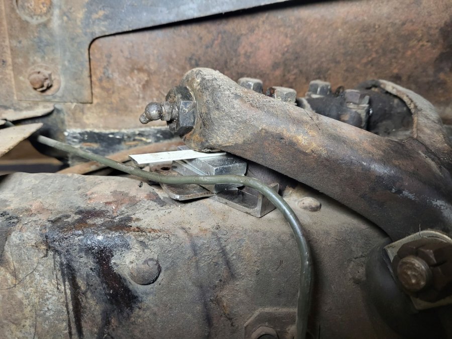
Once the grease nipple is removed, the distance from the edge of the opening where the grease nipple starts to thread in, to the end of the control arm rod, is about 1/8th of an inch. In the one picture you can see the end of the control arm rod with a countersunk end to it. So like I said, the grease goes in the grease nipple and fills that 1/8th inch cavity and then has to work it's way around the threads and eventually it gets pushed out the other side where the dust boot is.
-
While giving the old girl ( '48 Windsor) a grease job, one of the upper control arm grease nipple wouldn't take any grease. I thought it might just be a matter of removing the nipple and removing some hardened grease, either in the nipple or the end of the upper control arm bar. Not so. Fortunately I have a spare assembly out of a parts car I disassembled a few years ago. So I started to investigate and took it apart to see how it all worked. To my surprise, it seems like the up and down motion of the control arm assembly is based on the rotation of threads on the upper control arm bar and the end bushing that screws into the ends of it. The weird thing is that the only way for grease to lubricate the movement is for it to work its way between the threads. The end bushing that the grease nipple is threaded into, has threads on the inside of it and on the outside of it. The inside threads match up to the threads on the end of the control arm bar. The outside threads on the bushing, threads into the control arm. I would have thought that there would be a flat spot on the threads on the control arm bar, so that the grease could easily work its way down the threads. But not so. The other interesting thing I found is that the outside threads on the bushings are not conventional threads. They have a very "soft" low profile thread so to say. More like rolling hills and valleys than threads. They don't look like they have been worn this way, but rather manufactured this way. For whatever reason that is illuding me. So once these end bushings are threaded in tight, they move with the control arm. Obviously the control arm bar is bolted in place. So the rotational movement of the upper control, which is about 1/4 turn (I'm guessing) is achieved by means of the outer thread of the control arm bar, and the internal thread of the bushing. With all this in mind, I'm thinking I need to unthread the bushing. I should really take it right out and clean up the threads. I'm a little concerned about any pressure that is on the assembly. I'm thinking the way I have it, which is the wheel removed and the car supported by jack stands to the control arm assembly is hanging down. I'm thinking that that would create a downward force on the control arm, putting a downward force on the top of the control arm bar. So I have wedged between the bottom of the control arm and the frame. My thinking is that should relieve any pressure on the bushing as I unthread it. Any thoughts on that, or contradictions to my way of thinking?


-
I agree with you. Personally, I've never seen a car or truck from the late 30's to the late 40's that didn't look better with a visor. As for your issue, sorry but mine is not a Fulton and I don't have any first hand experience with them.
-
Chrysler must have had cheat sheets printed out that employees would carry in their breast pocket inside that handy pocket protector, that had all the numbers identified and associated with the particular car and years it represented, since there is no rhyme or reason to it.
-
This is a good question BobDeSoto. So didn't anyone at the big table on the top floor of the Chrysler building, including Walter himself, think that it all sounded a little confusing? lol Besides,,,, why bother? What would be wrong with just referring to the actual year and model of the car? Or would it be that by using a letter/number designation it would magically make someone sound more knowledgeable? Personally I think not. My 1948 Windsor is a C38. From years of thumbing through the service manual and my parts catalog, I've learned that the #38 referred to the 1946-1948 6 cyl, cars. But can anyone tell me what the number 38 actually represents? In all the years of owning my 1948 Chrysler Windsor, I have never referred to it as a C38.
-
It would be nice to be able to get at least one window out in one piece, to use as a pattern. The truck only needs the drivers side. But if I went to that much effort, I might as well replace both windshields. As for a new seal, would one use something like 3M 08008? That's what Steele Rubber always recommends when working with their rubber seal
-
As I mentioned the lighting in that 40 foot container was only from my phone. I couldn't see exactly how the glass was mounted. Is there an outside frame and an inside frame, sandwiching the glass? Yes there was some crusty loose rust around that frame for sure. Looks like I just answered my question by a diagram and images from DCM. Looks like the frame is a channel and the frame is in two sections. The glass is slid in from the centre. Meaning in order to replace the glass, you have to be able to carefully slide the old glass out of that crusty frame. So the condition of that frame is quite important. The reproduction frame, glass and seal is about $1500- $2000 CAD. delivered. Yikes !!! If it needs a regulator, that's another $500.
.thumb.jpg.d599d4c13e08899474e0348bd9baed3b.jpg)

