


Dick41
-
Posts
45 -
Joined
-
Last visited
Recent Profile Visitors
937 profile views


-
Hi Blue: Another two cents worth here. Mine is a 41 Plymouth flathead. I recommend a radiator inspection and recore if necessary. While I had my radiator done, I brought in the distribution tube. Expert radiator guy in Stockton, CA. said it was fine but put it in the boil out tank to clean it. Lookjed like new when he was done. There is no flare on my tube. Looks just like the rest of the pictures here. I went with the radiator recore job after all and am very glad that I did. Now my car can sit at idle on a hot day and not overheat. Driving, the guage is always in the middle range. What a relief!
-
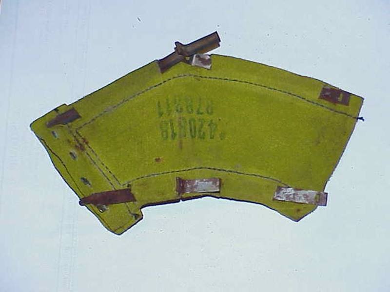
Very sorry if my original post caused any of you the problem I just experienced. I spent most of the afternoon learning that this wire pull method wouldn’t work for me. The new rubber boot got stuck inside the trunnion housing. I couldn’t get it in, or out, without tearing it out in little pieces.. That was the final result….little pieces and another rubber boot torn! I give up! I am going with the split leather one. No pin to press out of the shaft, no rubber to stuff through the trunnion housing. I have one of these leather boots on my 41 Plymouth and it is doing fine. So, after removing the grease from my hands, and the little rubber pieces from the garage floor, I spent more than 2 hours looking on line for split leather boots. Bernbaum doesn't carry them any more. I found a 2012 thread, leading to the source of leather boots, on the P15-24 forum. Here FYI is that link: http://p15-d24.com/topic/20381-plymouths-at-portlandjust-wondering/?tab=comments#comment-196498 The Source for split leather driveshaft boots is AMS Obsolete http://www.amsnos.com/ (They may have once been Mitchell’s Mo Par)? Phone: 706-337-4606 Fairmount, GA30139 See page 62 of their on-line catalog. Part #: 870311 ( 7A6 Leather U-Joint Boot) Price: $39.50 ea (+shipping) So I am now waiting on the leather boot. Picture of same attached below: Again, my sincerest apology to all: Dick Quite a while ago there were some posts on putting new rubber boots on trunion style driveshafts. My appliction (this time) is a 1956 Dodge Coronet. Without pressing out the trunion pin, that boot must be pushed (or pulled) through the trunion housing. This is the second time that I have had this "Pleasure". I contacted Andy Bernbaum and learned that the leather split replacement boot is no longer available. So, I went with the rubber one. After aout an hour of stretching, puling and resisting pokng with a screwdriver, I called it a day. Here is the good part. I found an excellent U Tube that shows how to do it. The guy is not selling anything (neither am I). But I was so impressed with his method that I wrote to Bernbaum just now About a 18 minute video https://www.youtube.com/watch?v=KBtEgMJFis8 In real time, the guy has the boot installed in less than 15 minutes. Some guys on this P15-24 Mo Par Forum quote as much as 8 hours. I can believe that 8 hours estimate until I saw this video. Here is a summary of his method, though watching the entire video was most hepful. 1. Make two U shaped wire loops (each leg is about 10 inches long) 2. Hook the loops over the boot 3.LIGHTLY LUBE THE BOOT INSIDE AND OUT LUBE THE SHAFT AND INSIDE THE TRUNION HOUSING THREAD THE LOOPS OVER THE BOOT AND THEN THROUGH THE TRUNION HOUSING PLACE VICE GRIPS ON THE WIRE LOOPS AND PULL THE BOOT THROUGH THE HOUSING. IT SURE WORKED FOR ME!
-
i woud only "cut" the drums if they are found to be out of specs. Manual says take no more than 30 thou off of the stock 10" drum. That results in a net diameter of 60 thou oversize. Again, no cut if drums check out fine, and certainly no more than the 30 thou in any case.. Plymouth Factory Service Manual, page 76-87 pretty complete on adjustment & how to do it . Also the use of the Thompson Guage/tool. On Pg. 79 - "These arrows on the anchor bolt must pont towards each other before starting to adjust the brake shoes." They must be turned in the proper direction to adjust the heel of the shoes. That would be the major adjustment you speak of. If heel adjustment is required, the arrows would likely not be pointing at each other when done.
-
Thanks Rich and everyone. i also find a person in California that loans the tool. Can't remember if that is you or not Rich H. I took another look at the r/f shoes last night. They were the most worn. Probably unevenly too. have decided that I am going to go the full route and get the drums turned and buy new shoes. After I get all the needed items and work done I will reach out for the very much appreciated tool. I am also going to look at the rod adjustment for the MC. I belive I previously found a how to do it in the 41 Service manual which I have. As a payback (or pay it forward if you will) I have a hub puller that I will loan out. This is a good one. Three fingers going to the lug nuts...Big thingy that you smack with a very big hammer. Works great. I have used it on my 41 Plymouth and the 55 Studebaker. Both have key axell drums. I will gladly loan to a member of this forum for deposit and postage both ways. Hope that might be of help to someone. As an additional hint: Somewhere on the forum I read that you don't want to grease that axel when you put the hub back on. Instead, use one of those really big chalk sticks and rub it on the axel. Works like a charm for me. Also, caution. Leave the nut on the axel loose so the drum doesn't travel across the shop floor when it finally comes loose. Experience is such a wonderful teacher! Backatacha soon.
-
Thanks to All who replied. After writing the question yesterday, I again checked my pedal- having already adjusted the shoes. Still almost to the floor until one or two pumps. Then have good brakes and pedal firm at about 2" above floor. So, if not air, I guess it is back to the fine adjustment. I may just try new shoes first. Mine are at about 50%.. You all may have saved me from rebuilding my MC or buying a new one. I second the motion *Earl* on the adjuster "Pain". Again, is there a backing plate substitutioin to get the more modern adjuster systems (I think Bendix is the correct term but not sure.)???
-
As I surf the forums looking for brake backing plate conversion information I came across this problem posted by Tyson. It is probably way too late to help a 2014 question from him. However, while working on my 41 Plymouth this week, i too found the bottom adjusters (the ones with the arrow) were no longer working on the right front. I had taken the adjuster bolts completely out and super cleaned them on the wire wheel/grinder. What the heck? Right side does not adjust the shoes, left side fine! Same process. Solution: The R/F bolts were not quite seated into the shoe! Seemed like they were fine but they were not. I loosened the bolts, made sure the eccentric shoulder seated all the way into the shoe and then retightened the bolts. Works Fine now. Duhhhhhhh! Any help on this one? I find the top and bottom adjustment on these stock41 Plymouth brakes to be very difficult. I fashioned a measuring device out of hardwood that works like the Elusive Thompson tool. This allows me to adjust the top and bottom of the shoe to very close tollerances with the drums off. I am hoping for a better pedal when i finish. I have bled the brakes until I am blue in the face and still the pedal goes to the floor. One or two pumps brings the pedal to acceptable point and the brakes work fine. There seems to be really good stream (pressure) when I bleed the brakes but the low pedal persists. I am thinking about rebuilding the master cylinder but am not sure that is the problem? Stock shoes are fair to good. Drums are within standards and are not scorred. Wheel cylinders and master cylinder are not leaking fluid. No leaks found in any of the lines. Are there alternative (salvage yard/used) backing plates that fit? I would lke to get to a single shoe adjustment system. Is there an alterntive (salvage yard/used) dual master cylinder reservoir that still allows the location of floor mount pedal in the stock location? Sorry if these solutions are somewhere in the forum. I have searched for several days and couldn't find them. Any help greatly appreciated!
-
Plz substitute Round for ound filter. Old brain in need of second cup of morning coffee :>)
-
Probably got all the answer you need by now. Just a bit of additional: I have one with a screen enclosed type ound filter (aout 2" diameter) on the top fo the tube where it goes into the block. A long Bolt goes throught the center and into the block. In additon, there is a rubber (i have seen felt ones too) round washer that goes on the flange just before it enters the bock. Not sure what that does except to seal the pipe until the fumes exit the pipe at the bottom .
-

Radiator Measurement needed 1941 Plymouth P 11 Coupe
Dick41 replied to Dick41's topic in P15-D24 Forum
Thank you All! Especially Ray for all those mesurements. Your diagram convinced me that I should go with a $350 recore of my stock one. The aluminum one looked nicer and would have been a better performer. However, I work so da%#&*m slowly sometimes that I wouldn't have been certain that i would have the front end and hood back on the car in time to meet the 60 day return policy with Ledfoot racing. By the way, Goeff at Ledfoot couldn't have been nicer! The aluminum radiator I ordered was sent back (at their cost for shipping) and the refund will be promptly made. These guys have a realy great company that I recommend highly. Wish I could have been more certain that their radiator would fit and clear the bodywork. -
Radiator Measurement needed 1941 Plymouth P 11 Coupe
Dick41 replied to Dick41's topic in P15-D24 Forum
Thanks Ray. I await your answer. As you can see in the diagram I drew, there are five holes in that mounting frame. As I recall, there are only three holes (on each side) of the radiator flanges. I wish I had paid more attention when I took out the stock radiator several months ago. Regarding this same request for information: Iif anyone has pictures of their 41 engine compartment that focuses on the inside face of the stock radiator (or shows that view) , that would also tell me what I need to know. Thanks again. Continuing in amasement and gratitude for the resources available from fellow members! Dick -
Hi All: Would one of you with a stock 41 Plymouth (probably all the same but mine is a business coupe) please get me a couple of measurements on the stock radiator? I ordered an aluminum one but it didn't fit. They will send me the correct one but need a couple of measurements. I have the measurements from the mounting frame but need to know how high (at the sides, and at the middle) the top tank is above the mouting frame sides. I no longer have the stock radiator so am unable to do the measurements. My concern is under hood clearance. Since the front end (fenders, grill, & hood) are off the car I can't do those measurements either. The PDF is my drawing and measurements on the radiator mounting frame. The other attached picture shows the stock radiator pre removal. Yeah! I know! No hair on the old guy! LOL Thanks in Advance Dick41 plymmeasure.pdf plym rad 2.pdf
-
Just now finishing up my driveshaft in my 41 Plymouth. It has the stock ball and pin type (see Bernbaum Catalog Pg. 73 Item Q 101 for picture). The rubber boot was shot. The shaft was running fine, no vibration and no wear noted when I disassembled it! The factory manual shows two washers with the assembly. One inboard from the needle bearings. The outer one is shown as a wave type washer. it is on the outboard side of the needle bearings and ball socket...just before the outside end cap. My driveshaft had none of the wave washers when I took it apart. The folks at Andy Bs. were kind enough to look at their complete kit. Their kt contains flat (non wave) washers in place of the wave type. There is virtually no side to side play in the assembled unit. I am wondering if I can leave out the wave washers totally, not even replacing them with flat washers. These wave washers are called centering button springs #19 in the factory manual diagram. It doesn't look like the needle bearings can get past that end cap (called a centering button in the factory manual #18. Both of these are on page 209 of that manual. I did find a source for wave washers at MSC industrial supply http://www.mscdirect.com/browse/tn/Fasteners/Washers-Shims/Wave-Washers-Springs?navid=12108761#navid=12108761+4287746935 Page 2070. I noticed Tod Fitch's earlier comment on this thread about rubber boots. Short of having the center pin pressed out of the shaft, there is no way to replace the rubber boot. Andy Bs has the split leather boot that installs without removing the pin and housing. Same as original (pg 73, Item # Q 103.) Saved me going to a machine shop, and the install went pretty easily. Hope this helps someone else chasing parts for a driveshaft. Your input please on those little wave washers....replace with new or leave em out? Thanks Dick
-
Armed with the location of a hidden frame number, my trusty wire brush and a flashlight, I pulled the left rear tire this afternoon. The mystery deepens! I found a number right where this forum said to look. Just to the rear of the rear axle on the outside of the left frame arch. What makes this more interesting is it is clearly a professionally punched number, very old looking too. It is only a partial number that reads: "L P 11 (eleven) L". Nothing else! Other than the aforementioned door plate on the right door hinge post, and motor numbers, I found one other on the firewall, just underneath the voltage regulator. It reads "8 6 6 7 5" The 5 is under the other four numbers. These too appear to have been applied by the factory. I had a friend in law enforcement run that door plate number and it came back clear, as did the existing WA state plate number. He also ran the registration number on the title and it too was clear. Sure lots of food for thought in the replies I have received; and I sincerely thank you all. Due to this, for now....call me Sleepless in Califorinia..... Not Seattle! Dick
-
Very Cool Thread indeed. Thank you all! Dick
-
Thank you all. Especiallly Furry for that info. from another 41. I am outa here with sandpaper, tire iron, wire brush, etc. to look for that number on the left rear tire frame arch (outside). I hope that location was standard for all the Plymouth 41s. I would appreciate contact information to send to Chrysler for the Build Sheet. Thanks all! Dick 41 PS May still be looking for a good running flathead L mill that fits. Mine has a 23 inch long head. Otherwise I will be doing a complete rebuild on one of my two available motors. I am already good friends with Andy Bernbaums LOL.
