


WPVT
-
Posts
115 -
Joined
-
Last visited
Content Type
Links Directory
Profiles
Articles
Forums
Downloads
Store
Gallery
Blogs
Events
Everything posted by WPVT
-
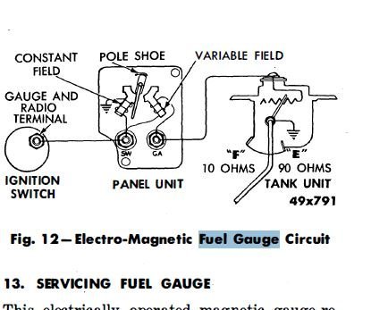
Thanks. I figured it out with an ohmmeter. The top wire of the coil is connected to a brass rod that passes through the center of the cone, and ends at the bottom rivet. So when it is riveted in place, the terminal is electrically connected to the top of the coil. The bottom of the coil winding is connected to nothing. I think this original old style has some advantages over the reproductions. The cone shaped winding means that the ohm variation isn't entirely linear, the way it would be if the winding were on a cylinder. Full and empty would still be accurate, but in between, less so. The original engineers were pretty good at their job, and weren't satisfied with "good enough". That's why I enjoy getting into the inner workings of these old vehicles.
-
Thanks so much. There's a little tab brass at the top of the coil, and something similar at the bottom. I think that a brass rivet held the coil in place at the bottom and that's what breaks. What's puzzling me is where and how the coil was connected electrically. Somehow, the top of the coil was wired to the hot terminal. Are there any clues on this piece ? Thanks again.
-
I removed the malfunctioning fuel tank sending unit from my 1954 C-1 truck. Sure enough, on opening it up, there were loose parts that fell out. Included in this was a cone shaped piece wound with resistance wire. I carefully put things back together. This is a single wire unit. The wiper contactor is grounded, one end of the cone is connected to the hot terminal. Reassembling, I tested and found that it did range from 9 oms to 90 ohms, just what the spec calls for. Unfortunately, the ohms are 90 when full and 9 when empty. So I must have inadvertently wired or installed the cone upside down. Does anyone have a photo of the sending unit interior showing the cone shaped resistor ?
-
Sounds just like mine. Turns out Vic's Dodger Garage has the exact match rubber. Washer/spacer/washer sounds like a more practical design when it comes to replacement. I'll reassemble mine that way. The motor mounts look the same, but the spacer design length was intended to provide with a bit of clearance...not compressing the rubber. That way they do their job a lot better. Compressing the rubber just serves to transmit the engine vibration to the frame. I'm not sure the cab mounts were intended to be left with clearance, though. They take a lot more stress in both directions. The spacer length on my cab mounts seems designed to allow the bolts to be tightened pretty firmly. Even after being squashed for all these years, the bolts were still tight on the spacers, so they must have been pretty tight originally.
-
Thanks. I contacted Vic to ask for dimensions to see if they would work. He's a great guy to do business with.
-
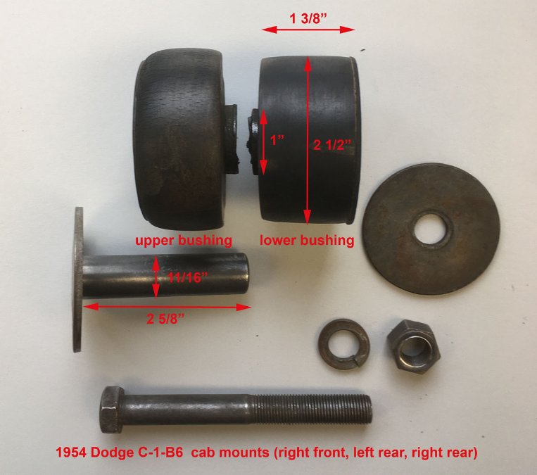
I was able to remove the steel spacers by using a punch, from above, to separate the spacer from the washer. The spacer was manufactured with a small shoulder where it was pressed into the washer and swaged. Once they were removed, I was able to jack up the cab enough to slide out the upper rubber bushing. Now it remains to find or fashion replacements. I am attaching a photo of the components. I am guessing that the the upper and lower bushings were originally identical, but the weight of the cab has distorted the upper. I think I'll be able to reuse the steel spacer by reversing the process I used to remove it. It prevents the bolt from being over tightened, which would negate the vibration dampening qualities of the rubber. I'm guessing that the rubber was a medium soft durometer when it was new, judging from the swelling that the cab weight induced in the upper bushing and the indentations from the large washers. At present, I've found no supplier that sells the bushings this size. Most are smaller diameter and thinner.
-
Thanks. I figured that the rubber might just be holding things stuck together, but I wanted to make sure I wasn't missing something other than the four bolts. Tomorrow I will get them separated one way or the other.
-
Thanks. I follow your procedure. Good news if the spacer is just pressed into the washer....I thought it might be a weld. If it's pressed in, I may be able to separate it with a punch from above. I hadn't considered that possibility. Putting a jack on the running board is also a good idea. If I jack off the floor, I may just lift the whole truck. I've located some polyurethane mounts that are the size I need. The thickness on upper one is critical if I'm not going to change the cab height. Thanks again.
-
I have a question for you, JB. I've got all four mounts unbolted and the bolts removed, so the cab is just sitting on the upper rubber mounts. The mounts don't really look "pancaked", they're just a little harder than I'd like to see, so I have in mind to replace them. My question is this. Everything is unbolted, but the cab still feels firmly attached to the frame. You would think I could at least rock it a little. The old rubber may be acting as an adhesive, but I've actually tried rocking the cab pretty hard. Looking at the mounts, I can see that nothing has separated, not even a fraction of an inch. Am I missing something ? Intuition tells me not to try jacking up the cab. It's a nice straight rust-free cab, and I don't want to screw it up.
-
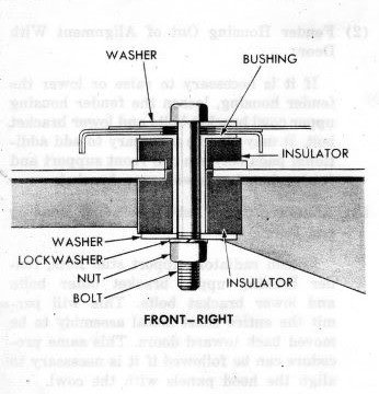
I'm replacing the cab mounts on my 1954 C-1-B6 truck. The existing stock mounts front and rear are very close to the image attached except that the lower part is 1 3/8" thick and the upper part is 1 1/8" thick. Both parts are 2 1/2" in diameter. I've seen some offered for sale that look similar, but not these dimensions. The 2 1/2" is fairly important, and the 1 1/8" dimension is also. The 1 3/8" dimension, the thickness of the lower part, could vary if need be. Does anyone know of a source that offers the mounts to these dimensions or close ? (The left front mount is different, but that doesn't concern me at this point.) The second part of my question involves the steel part labelled as a bushing. This is a tee shaped assembly consisting of a tubular spacer and a large washer. This was inserted from above, before the cab was installed. Obviously, this makes replacement a little difficult, unless you raise the cab up at least 2". I'd rather not do that, so I may end up separating the tubular spacer from the washer using a small Dremel cut-off saw to enable removal. I did this on my motor mounts, as they were assembled the same way. Has anyone run into this problem and did you come up with a solution ?
-
Funny you should mention that. My next project is renewing the mounts. Maybe that will help.
-
I was all set to adjust the valves on my 1954 218ci. I removed the wheel and all the nuts and bolts holding the fender inner panel. The inner panel was still pretty firm. It's not rusty but just tightly fit into where it is located. I looked long and hard at how it would have to come out and decided it would be very difficult to get it back in. So valve adjustment has moved to low priority. How difficult have others found the inner panel removal and re-installation ? It may be that the 1954 C series is significantly different from earlier B series models. Has anyone done this on a C series?
-
Still 6 volt. Pretty much all original, low miles. I'll remove the tank this week and pull the ailing sending unit.
-
This general topic has been covered in other threads, but before I remove my fuel tank to repair the sending unit, I thought I would describe the situation to see if anyone had experienced a similar problem. My truck is a 1954 1/2 ton. The fuel gauge doesn't work at all until the tank is almost empty, at which point the needle swings wildly from left to right. This happens very dependably...it's not erratic. A nice feature to get one's attention, but I'd prefer that it worked conventionally. My cab floor access panel does not line up with the opening on the tank, so servicing the sending unit means dropping the tank. Has anyone had that specific malfunction ? It seems to me that the wiring and ground must be OK, and that the problem must be the unit itself.
-
As I suggested in an earlier post, disconnect the fuel line at the carburetor. Turning the engine over with the starter, there should be a good stream of fuel being pumped. If there isn't, you have a fuel problem between there and the tank. Basic troubleshooting is quicker and easier than speculating. Checking for fuel supply is a good first step.
-
If letting off the gas for a bit temporarily cures the problem, it sounds like a fuel delivery issue. The carburetor may be running dry, and then letting off the pedal lets it build up a little more fuel in the bowl to run again. Replacing or rebuilding the fuel pump couldn't do any harm. Often they become marginal...sometimes working well enough , sometimes not. Along the same line, you might check any fuel filter that you have, as well as a restricted fuel line. The short flexible line that connects the pump with the steel line to the tank can fail. It's under suction, so it can collapse internally. Your pump should be good enough to send a steady stream of fuel to the carburetor with just the starter motor turning over the engine. Disconnect the line at the carb and see if the pump is getting gas there. Don't be fooled just because you see gas in the glass sediment bowl. It can be full even though the carburetor is dry.
-
Thanks everyone. I just completed replacing the rear engine mounts on a C-1. It took about two hours work, but 2 weeks of research. I learned some very important basic principles about this mount design that I'd like to pass along. The C series mounts are a little different than the B series, but the basics apply nonetheless. The mounts use a rubber donut and steel washer on top that the engine rests on. Then comes the frame. Then comes either another rubber donut (C-series) or a rubber washer (B series) followed by a steel washer. Running through these is a long, fine threaded bolt, and a tubular spacer that determines the distance between the washers once the nut is tightened. The tubular spacer is integral with the upper steel washer, making a tee shaped assembly. That's unfortunate when it comes to disassembly, since there isn't room to lift out the tee assembly from above in one piece. Here's what I did to disassemble and remove the old mount. I removed the lower nut from the bolt. On mine the nut is 11/16 and the bolt head above is 5/8. Then I removed the steel washer and the lower rubber donut. Using a Dremel and a cut-off wheel I cut as much as I could off from the tubular spacer...about 1". Then I jacked up the engine about an inch or so and after lifting the bolt up through and removing it was just able to slide the upper rubber donut and the washer/spacer assembly out sideways. I put the tubular spacer in a vise and cut the washer off flush. My new assembly consists of the two steel washers, top and bottom, separated by a loose tubular steel spacer that I made and cut to a very precise length. That length is critical. Now I could insert the spacer from below when re-assembling everything. There's been a lot of postings regarding the hardness and dimensions of the mounts that are currently available. Also the fact that the B series used only a rubber washer on the bottom yet suppliers only sell a lower thick rubber donut. Those things don't really matter. What matters is understanding the principle behind the original mount design. The engine rests on a steel washer, which rests on a rubber donut, which rests on the frame. Underneath, there is a rubber donut or a rubber washer...either will work. The bolt that passes through this sandwich has a tubular spacer that prevents the assembly from being tightened beyond a certain point. THE most important point is that the spacer has to be a precise length that will prevent the rubber from being clamped tightly. The engine weight rests on the upper rubber donut, and the lower donut or washer is NOT brought up tight against the frame. There is intentionally a small gap left there. The lower mount fastening will prevent the engine from spinning over, but it's not supposed to be tight. Tighten it up, and the engine vibration will shake the whole truck. Leave it loose, and it does its job and prevents engine vibration from being transmitted to the frame and cab. I would recommend replacing the mounts to anybody with an old truck and old mounts. If you do it as outlined above, the difference is like night and day. I hope this post proves helpful.
-
They are rubber mounts.
-
Any advice concerning replacement of the rear motor mounts would be appreciated.
-
Dimension needed-'54 Dodge C1B6 rear differential
WPVT replied to lonejacklarry's topic in Mopar Flathead Truck Forum
Good luck ! Let me know if I can be of any further help. My truck appears to be pretty original and it's the same year and model as yours. -
Dimension needed-'54 Dodge C1B6 rear differential
WPVT replied to lonejacklarry's topic in Mopar Flathead Truck Forum
I've done my best to get the dimensions accurately. Not sure what degree of precision is needed. I'm probably within a half inch or less. I didn't remove the wheels, so I had to do a little math, but I was careful about it. The total width you are seeking is 62 1/2". Although the differential housing appears to be centered, or nearly so, the driveshaft is offset 1 1/4" from the centerline of the width I gave you. It's closer to the passenger side. I hope this is helpful to you. Are you trying to match up a replacement, or fabricating something like in your diagram ? -
Dimension needed-'54 Dodge C1B6 rear differential
WPVT replied to lonejacklarry's topic in Mopar Flathead Truck Forum
Thanks for the clarification. I might not get back to you until this afternoon. -
Dimension needed-'54 Dodge C1B6 rear differential
WPVT replied to lonejacklarry's topic in Mopar Flathead Truck Forum
I have a C1-B6 1954 truck. I'd be happy to check for a dimension tomorrow. Can you be any more specific about what dimension you need ? ( Maybe it will be more obvious when I'm under the truck. ) -
The engine vibration that I am experiencing with my 1954 C-1-B6 pickup seems excessive to me. The engine runs pretty smooth, but it seems like too much engine vibration is being transmitted to the frame and thence to the steering wheel and cab. I've read everything on this forum relating to motor mounts. Mine don't look that bad, but they are undoubtedly old. So in the interest of experimentation, I loosened all of the mounts, front and rear. I jacked up the engine about an inch and started the truck. Much smoother, of course. True "floating power". I'm going to take the truck for a spin tomorrow with the engine mounts loosened to see if that is an improvement over when they're tightened. My theory being that it will give the engine a little more freedom to vibrate, without that transmitting to the frame. (All the bolts are in place, so I won't lose the engine.) If I decide that I need new rear motor mounts, I have quite a puzzle ahead. The lower rear rubber mounts aren't a problem but the upper rear rubber donuts won't come out without first lifting out the steel washer/spacer and that's going to require more clearance than seems to be easily available. I'm not ready to take extreme measures unless I can be sure there will be a significant benefit. Has anyone replaced the rear mounts without pulling the engine and been pleased with the results ?
-
Can someone recommend a source for a complete OEM type exhaust system for a 1954 1/2 ton 218ci Dodge ? I'd like to get as close to the original as possible, quiet, not loud. I know I can go to my local muffler shop, but I'd like to keep as close to stock original as possible.
