cdnpont
-
Posts
32 -
Joined
-
Last visited
Content Type
Links Directory
Profiles
Articles
Forums
Downloads
Store
Gallery
Blogs
Events
Everything posted by cdnpont
-
1 1/8" was the original size Matt. And yes, the owner did retain the stock drum brakes.
-
Thanks! Hopefully it'll give some ideas to others that might be considering something similar.
-
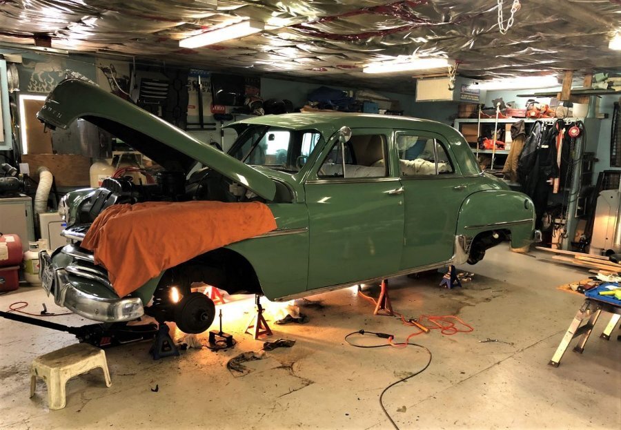
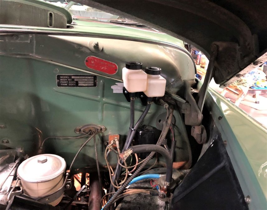
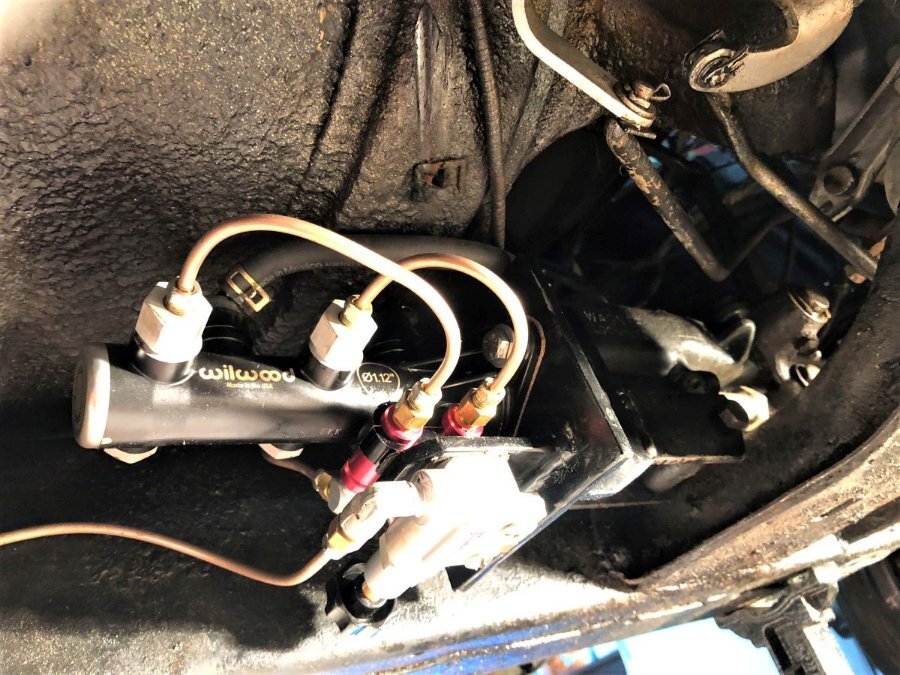
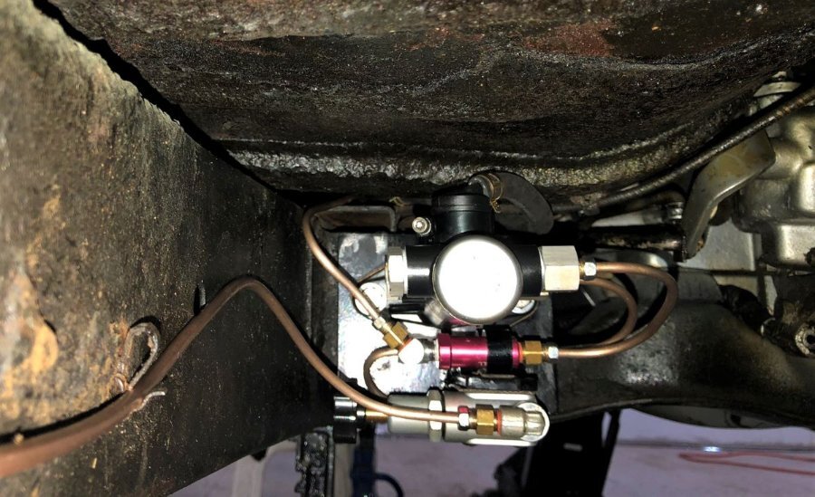
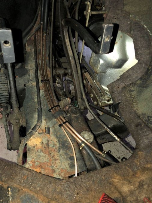
Update! dual system in, and working well right from the get go. who would have thunk it? Time was spent on the initial shoe adjustments, so the brakes pulled straight and true on the road test. The new 10lb residual valves did as expected and kept the shoes out where they need to be. No initial pumping of the pedal like before required. I did initially have a concern that the 1 1/8" dual master would have created far too hard of pedal. But not so, the pedal is absolutely perfect and I can fully recommend the size choice. All new Copper Nickle lines, flex lines and wheel cylinders made bleeding the system a breeze. Basically fill the reservoirs, open the bleeders one corner at a time (two on each front, bottom first), wait for fluid to appear at each bleeder. Having the remote reservoirs so high up really helped with gravity. The final pedal bleed was a breeze. Just 3 flair nuts needed a retighten in the system, which is pretty good in my books. We were VERY careful when installing the caps on the master and the drains on the bottles. They are O ring sealed and have a reputation for leaking. A little bit of dielectric grease on the O rings and a careful positioning and tightening of the clamps...no leaks. The master bracket seen in the initial post worked well, although a little trim to the length was required at that forward bolt slot to clear the crossmember. As seen in the image (with a test bolt in place), my diy through rod used the original 7/16 - 24 eyebolt at the pedal end. Had just the right about of back-forth adjustment built in to allow for just a little play at the master before pedal take up. I got lucky with my eyeball engineering! For those who might care, Initially, we hooked up temporary bleed lines from the master outputs up to the fully plumbed in remote reservoirs, to essentially "bench bleed" the master in car. We used two small flared lines at the master, connected by clear tubing up to two little hooked lines at the reservoirs. Again, worked perfect. The air was easy to see and very happy to travel up the line and took maybe 5 minutes of slow pedal pushing to clear. We already had the new front/back lines fitted, removed and pulled to a little to the side close to the master outputs. So it made for a quick changeover from the bleeders to the mainlines. Very little fluid was lost. Yes, we had to move the red firewall build plate more center to fit the reservoirs. The spot chosen was really the best position for them. Purists will cringe at the plate move, but the bottles look pretty good up there we think. Almost factory looking if they ever had done this. The rubber feed lines to new the master "caps" are very close to the floor and crossmember, but fit through just fine. We were able to reset the floorboard panel in place on top of the new feedlines and front brake line, it was tight, but to protect the hoses, we placed a small mat of rubber over them first. We chose to go with sections of hardline in combination with rubber up through this section for durability (and ease of install). The hard lines all have a little bit of a flair hump done on the ends to help with sealing them in the hose. Good project, with an appreciable increase in safety! Thanks for all the input.

-
Completed the master/valving/bracket and associated lines. Still have yet to make a pushrod extension. Just waiting till July to get to the car then the fun begins. Thanks again to the members and all the good ideas...
-
At the steel mill where I worked, new cold mill work rolls would arrive in coated in what I assume was Cosmoline. And being a new kid in the yard gang, we'd be sent over to the roll shop tasked to remove it. At the time, the only thing that that would even touch it was Trichlorethylene. A now banned and toxic substance, we merrily got soaked in it taking the stuff off.
-
Would the original grease not be pretty much petrified by now?
-
How do you "Bench Bleed" a remote reservoir tandem master?
cdnpont replied to cdnpont's topic in P15-D24 Forum
Yes, if disconnecting the connections at the master with fluid filled lines, this will be a godsend. Should be little to no drainback. So the suggestion is to just hook it all up as dry, fill and bleed it all at the wheel cylinders? -
How do you "Bench Bleed" a remote reservoir tandem master?
cdnpont replied to cdnpont's topic in P15-D24 Forum
Thanks guys, Both would be so much cleaner of a job. Can you imagine the mess using lines up the the reservoirs? This master doesn't have bleeders though. The master has ports on either side to choose from, you just plug 2. But they all are all 1/2-20 UNF with a crush washer, so a 1/2-20 UNF male/female to male bleeder adapter might be tough. Haven't looked for one yet. The vacuum idea is a good one...if only I can adapt some bleeders onto the master it would make for a super clean job. -
A question that has me thinking probably too much, We'll have a Wilwood tandem remote master conversion in the 50 Plymouth, reservoirs mounted somewhere up on the firewall or wheelwell. Is there a way to bench bleed such a master before installing it? Or must it done in car? How could you possibly manage the entire closed system on a bench, and be able to transfer it back into the car when bled? I'm thinking, in car, two separate bleeder lines made up that can reach up and into those reservoirs. Fill, pump pedal, and watch until no more air is seen up top? Disconnect the bleeders, re-connect the brake lines? Seems like a painful process, as the distance the air bubbles must travel up to reach the remote reservoirs is quite far. It's not like bench bleeding a standard open top master on the bench, where you can see right down into the ports and watch each tiny bubble appear. Any thoughts, I see nothing on line so far of how to approach this. Thanks, Mark
-
Great info. Thanks guys. To be realistic, on this round we won't be doing a booster, but now I'm second guessing our choice of master bore size at 1 1/8" which is another subject all on it's own.
-
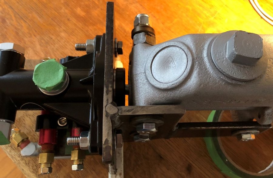
Oh, one thing I only just noticed is the two lower bolt holes for the master are offset horizontally. And don't laugh at my DIY slots!. Pre drilled everything. I then welded the one 2 hole side section square to the face plate, bolted it onto the old core, with the new face square to the old, then bolted the small rear extension on, lined the gap up, then made that weld joint. Was looking at it today, and thought, hey, I screwed up, the holes are way off! Looking closer, turns out the front bolt boss on the original master is lower then the bottom rear being square to the end cap. Small thing,
-
Thanks Sniper and Sam, I agree a single diaphragm master might not be worth the trouble. But I do know they make a dual diaphragm compact 7" Booster. Does that double the assist? I kind of visually estimated (from images only) the distance from the master centerline to the floor and it can't be much more than 3". The issue is a dual 7" booster is really closer to 8" in diameter at the locking flange. I guess if thee was a will, there'd surely be a way. Like make a hump in the floor under the drivers seat... I did originally think of leaving the bracket to basically float from the side of the master only, and would have built in more gusseting (still might). But we will be through bolting the new master, new bracket and frame box together. This should tie it together on the outboard side.
-
Thanks Guys, I now have myself wondering if we couldn't have included a 7" power booster under there as well. Probably too tight to the floor along the master centerline though. I see you can buy entire booster/master kits with a pedal. Too much work to fit a different pedal, along with fitting the clutch pedal I'd assume.


-
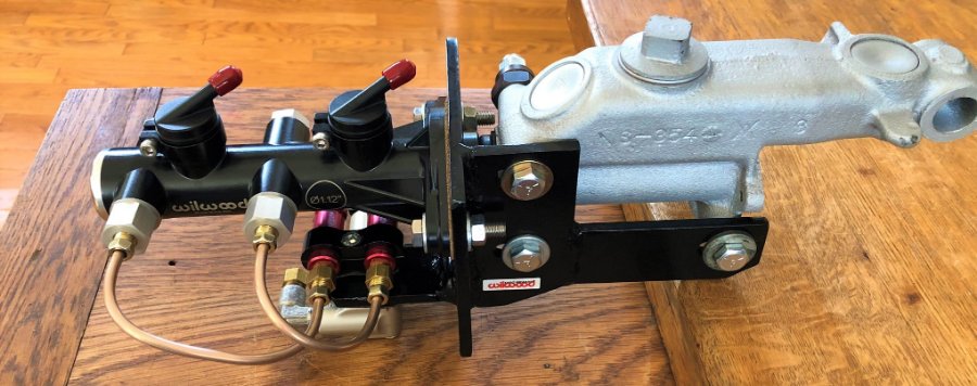
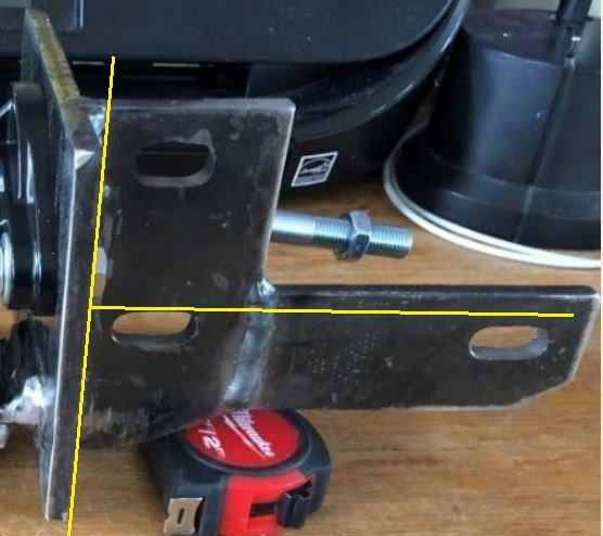
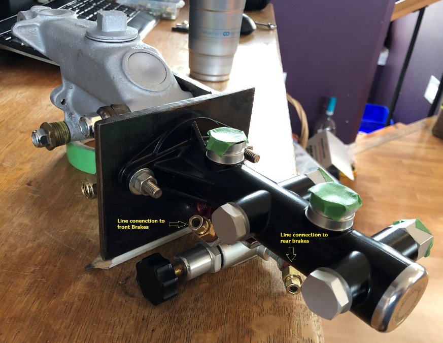
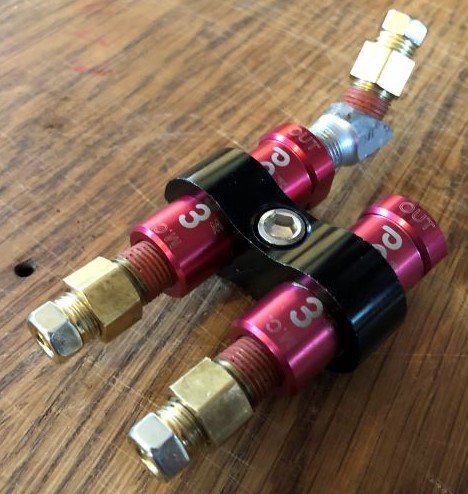
Thanks for all the help and ideas in my previous posts guys, A little progress in the project. I now have a bracket made up, 1/4" plate. Drilling the 1.5" hole in the face was a challenge, but this cheap carbide metal hole saw made quick work of it in the drill press. Be sure to adjust your speed to around 300, and keep steady pressure on it with light oil. Amazon part. Now Mocking up the mount position of the adjustable valve and residuals, trying to find the best spot to allow easy connection to existing (or new if Req.) main lines. I'll mount the adjustable valve knob inboard, thinking for protection and ease of adjustment from the down on the lawn lol. The idea is to use a good existing stock front bellows seal, and drill a drain hole in the bottom of the old core as a drain should water get in. Not likely as the car is dry driven only. Using a fancy little 8an hose separator to mount the checks. A little nicer that having them hanging free I figure. A tiny bit of tape on the Wilwood valve and they clamp in tight. Amazon part. The entire main bracket can be moved forward and back on the original master, as all 3 bolt holes in the side plate are slotted. This movement should easily allow the faceplate to meet and bolt to that frame box back surface as required. Again, I we had the car here, this wouldn't be an issue. As a bonus, we'll be able to pull the new master forward into close contact with the old, and should allow us to place some kind of simple DIY rubber seal between the two. The provided Wilwood pushrod comes way forward into the old core, so not much of an extension bar will need to be made. Maybe 4.5". Nice. Cheers, Mark.


-
It's not mine Sask. That's just a image from the internet. From a nice P15 for sale in the states I think. I'm working on a friends 50 Deluxe, joined the site for some good info. Cheers.
-
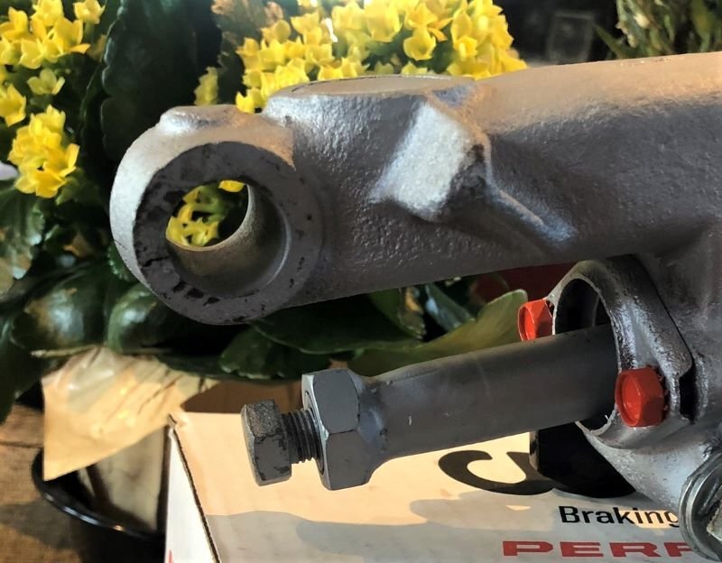
I'm surprised you guys are so quiet about it. Must have been pressed too hard or the pin struck in some way. Ting. If only it was steel.
-
The core I picked up for mocking up a bracket for a dual master conversion is cracked at the pedal pin boss. No biggie as it's really just for the bracket measurements (we will use the one in car), but the crack wasn't at all evident until I cleaned the casting. Common? Or from forcing the bushing in or out, or whatnot? I don't know, If I had a P15, I'd be having a close look through the dirt and grease at this spot. I can only imagine the issue if that boss was to chunk out and the pin was to slide forward. Maybe it never happens? Be safe,

-
The stuff was actually a curse at one time wasn't it.. In the rust belt, all it did was trap dirt and moisture against the line, and as such always shortened the lines life. One thing about it though, even if you don't keep it on, putting it down on the line makes it real easy to hand bend a extra tight turn without kinking it. Especially with the CuNi.
-
Beautiful. Thanks again PA'! I have a bunch of Copper Nickle 3/16 line. Do you guys bother anymore with the stone guard spring wrap? I'm thinking it might still be a good idea on the areas that might see some kick up. The CuNi line while being more corrosion resistant, might be a little more prone to getting nicked. Maybe not?
-
Simple question: What size are the brake lines running out from the master...on a 1950? 3/16 or 1/4" Thanks, Mark

-
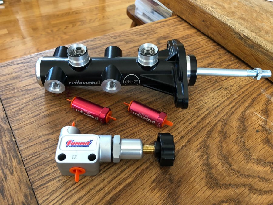
Some parts came today. Wasn't sure if the master would include a pushrod as the description varied, depending on where you looked. The thread on the end is 3/8-24, which'll make it just a little easier building a pushrod assembly. Also, it'll not ever come out of the master if something was to happen to the pedal stop bolt. Anyway, this is sure one nice looking master. Should be more than compact enough to keep it low and away from the floor, even with the top spigots in place.
-
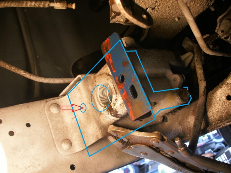
Thanks PA' Do all P15's share that same (or similar) front brake line distribution block? Same position on the frame?
-
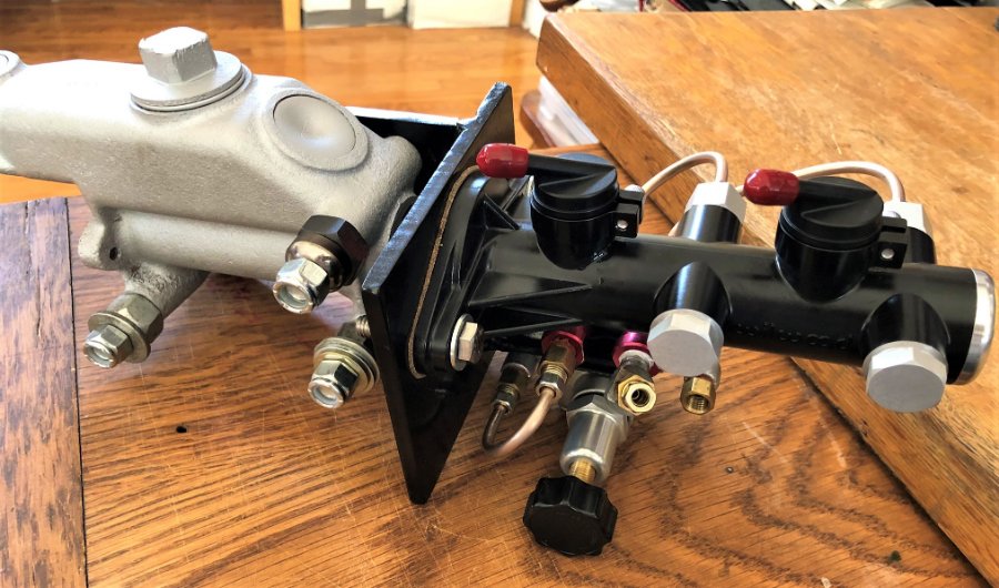
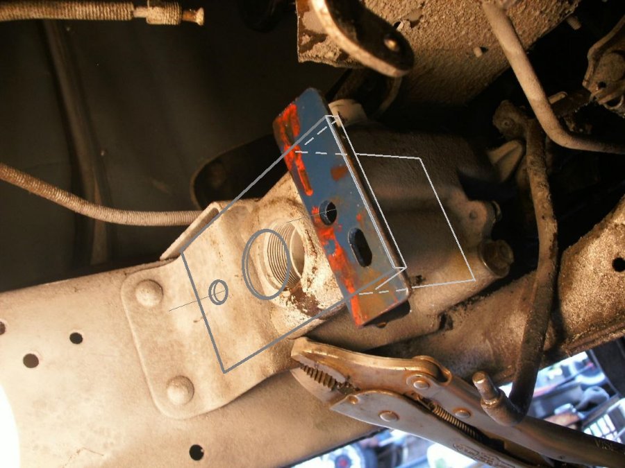
I like how you kept the original boot on the master with the new rod passing through it. Convenient to have that crossmember! How thick do you think the spring attaching eye would be? Maybe 1/16th or so? Here's another shot I grabbed at some point from here, as I really liked the super simplicity of this mount. I just wanted to make it more ridgid. Our rough plan is to fab a 2 piece bracket such as seen below. One large hole for the master (centered with the old) and 2 smaller holes on the face to mount it. Inboard hole passing right through the master frame mount box. Another side section welded to the front section, with the 2 mounting holes slotted to accommodate any fore/aft when attaching it to the old master core, and the butting back up to the frame box. We have no measurements to go on, and I'm sure the tolerances are all over. The slotted side holes should take care of that, and we'll drill through the frame box last. The side plate is kind of planned as a mount for the adjustable rear proportioning valve, and the 2, 10lb residuals.
-
Thank you for the info. The bigger size moves the rod end into a less common bore and thread size now. Maybe, after all, we'll just make a rod using the existing pushrod when we can get to the car...or perhaps still pursue a DIY solution here before we go. The thread on the stock pushrod eye looks 7/16 as well. I can at least have all the right hardware to take down in June. That and the bracket made with the new master mocked up on it. Thanks guys.
-
Gotcha! Edited same.