


Marc123
-
Posts
13 -
Joined
-
Last visited
Everything posted by Marc123
-
I have not checked the compression on the engine. I DID unplug each spark plug and each one slowed the engine slightly and the engine sound changed a bit differently for each cylinder. It was raining slightly so that made that task a bit more exciting. My only real experience doing compression testing was with Aircraft engines. I always use a leak-down type tester. I was told the type that simply has a valve and records the peak pressure reached "Are Only Testing Your Starter and Battery Charge". I don't know what the consensus here is on that?... With a plane you have to pull each cylinder to absolute TDC, often adjusting it under pressure until It just balances. If it's not dead on, the prop will spin 1/2 to 1 full rev. The back side of a prop it actually sharper than the front. It is actually quite dangerous, It's usually best to do it with two people. Once you get it all set up, you listen for leaks on the intake, exhaust and inside the crankcase to identify where it's leaking. I presume the same approach would be used on these engines? Marc
-
That's good to know. I wouldn't do it when replacing bolts on an engine, but I do tend to use grade 8's for everything else I bolt together. Thanks.
-
I noticed some of the sample Industrial Data Plates have a 5 digit Serial #. My Vehicle Data Plate lists the "Motor No." as 58826. Could that be the same as the Missing Engine data plate Serial #? Would the serial Number actually tell me anything?
-
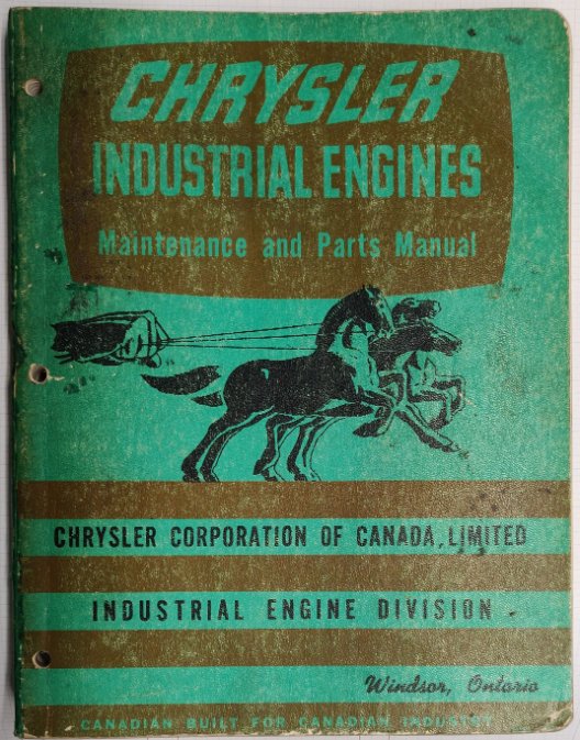
Actually based on my measurements and the industrial engine manual I just got it actually looks like it's a 251. Why would grade 8 bolts be an issue? The front left pad is BLANK. There are no ID plates anywhere else on the engine. The Industrial engine manual says NOT to use the front left stamp numbers as are not representative of the actual build. It says to use the plate riveted to the right side of the block. I don't have one. This is the manual I just got, it's dated 1960 and is listed as WM-4586 I don't know how or why it differs from the Orange and Yellow 1960 Manual shown in the above thread,
-
Finding Parts from Original MOPAR Numbers.
Marc123 replied to Marc123's topic in Mopar Flathead Truck Forum
OK, that's good to know. This loader has been neglected for quite some time. There are a lot of things I have done to fix it up this summer. It used to overheat all the time, step one of using it was always to drag out the garden hose. I have neglected the first rule of testing, Change ONE thing at a time... I put a new water pump on it. the bearing in the old one was literally the worst condition I have ever seen a bearing in, I don't know why it didn't seize up. I dropped the oil pan beat out the dents and fixed the original leaks AND all of the new ones I created with my fix... I rebuilt the carb. I removed the distributor, cleaned it up as well as I could, put what are undoubtedly the wrong springs in the centrifugal advance mechanism, and installed a "Hot Spark" Solid State ignition. I installed the ballast resistor and Bosch coil Hot Spark recommended. By sheer luck I think I found an appropriate oil filter to install in what I think is a partial flow oil filter. It didn't have anything in it before. I rebuilt the incomplete emergency brake based on guesses and presumptions on how it should work. I need to revisit that. I had a large explosion in the block when trying to get it to start before I updated the ignition system. I'm trying to get all the Carb and Timing settings figured out. Currently it's leaking quite a bit of oil around the timing chain cover and spewing a LOT of smoke out the oil filler cap. The old gauges did not work. I was overjoyed when the new Oil pressure gauge showed 60 PSI. Now it's showing 20. Previously I could barely turn the engine at all with a socket and breaker bar on the nut in the front on the engine. That had me worried about how I was going to turn it to find TDC. Now I can turn it over via the fan blades with some effort. That solved my problem of finding TDC, but overall is probably a bad sign. I probably won't be so lucky, but I'm praying I simply got a bunch of gas in the oil, thinning it out and causing the leaks and smoke. The exhaust system broke off the manifold where it had been welded on and there is at least one crack in the manifold. That makes tracking down exhaust leaks and smoke in general a bit tricky. Thanks for the info on the coolant system. I wondered if the were ever actually pressurized. Marc -
I finally found a parts manual for my loader and thought my problems were over. Not so. The radiator cap and overflow are not quite right. There is what I presume to be a sealing surface under the cap, about 2" down. The overflow tube is bent up, but basically just sticks up in the with no attachment, nor does it come into the Side of the radiator filler neck. The Top of the filler neck also has what I presume to be a sealing surface. The cap it has had since I got it simply seals at the top. The radiator will hold no pressure, as any pressure or expansion simply goes out the un-obstructed overflow tube. I presume something is damaged in my system OR the Correct cap is a two level seal type system. I figured now that I have the part numbers some Googling would provide some info or pictures, No such luck. The Radiator is a "Chrysler 1074 948" The Cap is a "Chrysler 962 330" Neither of these numbers map to anything modern. How would I go about finding info using these old part numbers? Thanks Marc
-
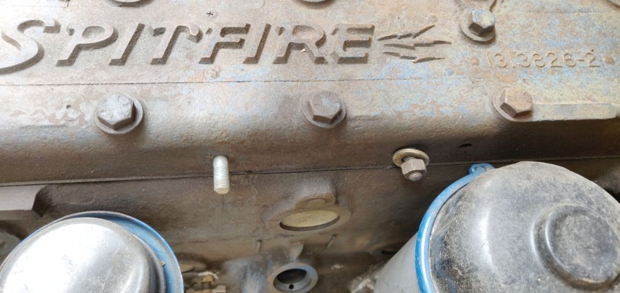
I have a loader with a Chrysler Spitfire engine with a 25 1/4" long head and a 4.5" stroke as far as I can measure. The Block has a casting date of 2-17-53. The head is embossed with the Spitfilre logo, if I means anything the head has |3|3826-2 <DOT> on it. I was thinking it was a Chrysler Industrial 265 engine. I got the parts manual for the loader. It says the engine original was a Chrysler Industrial 8A. Are they the same engine?
-
That is what I presumed. Disconnecting the hydraulic pump didn't change anything. The whole assembly appears to be solid. The parts manual lists it as a PTO pulley. Inside it there is what a presume to be a threaded nut with a hole in the center and two angled teeth. I presumed it was for an external crank starter and the angled teeth would kick it out once the Engine starts. Maybe it's to drive something else.
-
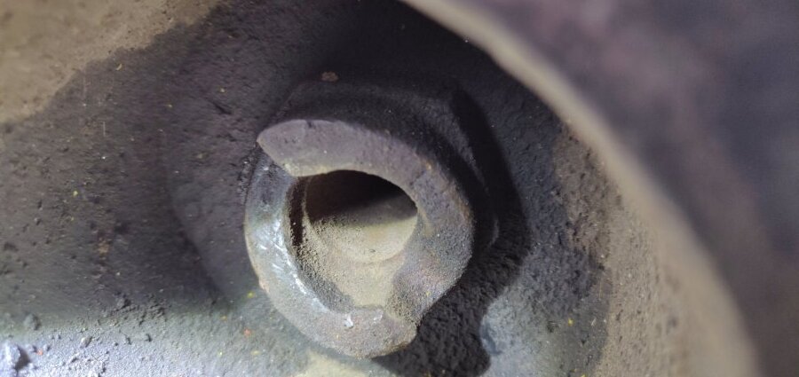
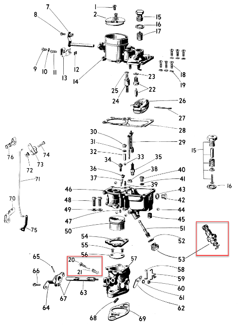
Thanks everyone. That's a lot to reply to. I did check the valve positions and verified when Cyls #6 & #1 where on the firing stroke. I've had the distributor off and cleaned and lubed it in addition to converting it to a Hot Spark solid state ignition along with their suggested ballast resistor and new Bosch coil. The Hot Spark docs say "The timing may need to be adjusted by as much as 30 Degrees" after the conversion. I am assuming that would be due to mechanical and possibly capacitance differences, and the 'Adjustment' would be to get get the plugs to fire at the Correct position RATHER than changing the actual firing position by 30 Degrees. That's good to know about the springs. None of my docs cover my particular distributor, a Chrysler "Auto Lite" "Solar Spark Ignition" IAD 4040-1. I'll have to pick up a compression tester, I almost bought one when I picked up the electronic advance timing light, but didn't. The wife was with me and was already getting annoyed at all the additional stuff I kept finding and adding to the cart ;-). My projects seem to have a bad tendency for me to put a lot of time into fixing them up and THEN finding or causing a huge show-stopper. Like spending a month installing a New 22hp engine on our Chipper/Shredder along with all necessary modifications to make it fit and fabricating an appropriate pulley for the engine. We used it for about 3 hours and it worked like a charm. Until... I was using a heavy machete to split off branches and stuff coming off at odd angles to fit some stuff in the chipper side. I threw the wrong handful of stuff into the chipper and the machete busted one of the blades. I can't get blades for it anymore. They are odd shaped and I'm not confident enough that I could fabricate and harden the CORRECT alloy in order to make new ones. I found a very common style and size of blade. Modifying the 5/8" mild steel chipper blade plate to accept them is a safer bet and a project for the winter. Or a month spent fixing up my 1958 Fordson Major Diesel tractor. It worked, but there were a lot of little things to fix up and considering I had never drained or replaced all the oils and filters, I figured I should do it. When I was done, the '303' combination Gear / Transmission / Hydraulic oil leaked out the bottom like a sieve. I figured I had overdone the cleaning with a pressure washer and caused it. Two weeks ago we got a notice in the mail about a big class action lawsuit over the brand of "Tractor Fluid" I used. They are claiming it was a bad formulation and among other things eats up the seals. The carb is a Series 228 downdraft Zenith with an adjustable main jet. The position of the Idle screw makes it a 228 rather than a 28. They both use the same rebuild kit. Getting that all adjusted is the next thing on my list. One of the engine manuals mentions a Wick in the center of the distributor shaft under the rotor. Can/Should I pack some cotton balls or felt in there and saturate it with 30 wt. oil? Yes, that picture is the loader in question. Mine does not have the optional door or glass. Due to how they were manufactured and used there always seems to be a lot of modifications guys have made over the years. It's not clear in that picture, but the front wheels contain a 3:1 planetary gear reduction built into them. That horizontal bar locks onto a splined shaft connected to the sun gear and is designed to be removed. That disconnects them from the drivetrain. The single rear wheel has a mount point for a tow-bar. The idea was to tow them with your dump truck to the gravel pit or temporary batch plant site and use it short term then easily take it home. The Industrial engine manual I have does not seem to cover the front pulleys shown above with the timing mark. The inner one with the timing mark drives the water pump and generator. The outer 3 drive a very large hydraulic pump that powers all the hydraulics. Is it possible the inner one contains a dampener or balancer of some sort and the load when running twists them and the timing mark out of position when it's running??? My explosion I mentioned earlier blew out and ruined the gaskets for the side valve covers. I am cutting some new ones out now, it's not sitting level and leaks a lot of oil. Once I get them on I'm going to disconnect the Hydraulic pump and generator belts to see if I can feel any play and if the timing marks end up closer to where they should be. Thanks for all the suggestions. Marc

-
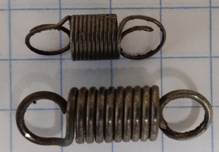
On this particular engine there is a plug, as in 'Pipe' Plug over the #6 piston. I pulled it out and used a rod and dial indicator to find what I assume ( I'm married too..) is Top Dead Center of the exhaust stroke. That is Supposed to be TDC on the firing stroke of Cylinder #1. There is hardly any movement of the pistons for a fair bit of rotation around TDC. I split the difference between when I stopped feeling it coming up and when I could first started to feel it go down. I Presumed that was TDC. Is TDC considered one of those other points rather than the middle? I did that 3 times without looking at the existing mark and tainting what I was feeling. They all came out dead on that mark. The valve stems and tappets are accessible on the side of this engine. I have the covers off. I didn't measure the Exact clearance but a 0.010 feeler gauge slipped under both valve stems on #6 when it was aligned with the mark. I rotated the crank 3 more turns and the feeler would slip under the valve stems on Cylinder #1. I 'Think' that proves the timing chain has not jumped a cog and the cam and crank are in sync ??? The plug mentioned on Cylinder #6 had a fair bit of carbon on it and a bit I had to break off when inserting the rod to feel the piston position. I have no idea if the Carburetor is set correctly or if I messed up the rebuild. The carb is a Zenith 228. The idle mixture screw is tight, then backed out 1 1/2 turns. The Main jet is also adjustable, it was tight then opened up 4 1/2 turns. I messed with them a bit but nothing got better, I could only make it worse. Could a really BAD Fuel/Air ratio or a bunch of crud in the cylinders slow the flame wave front in some way making the extreme advance necessary? The mechanical advance on the distributor had one 'light' spring under a bit of tension at rest and a heavy one that didn't even make contact until about half way out. I made two matching ones from springs I scrounged up from who knows where, based on no real specs. The only springs I could buy were off eBay, they had no real specs and the markings on the package when I got them said 'Ford'. Neither set made any difference. Here are the originals, the graph paper is 1/4". I am Assuming.. all that is irrelevant and could mess up the amount of advance at different RPMs, but not cause this. I figure the timing light is the final authority on when that plug fires. Is that a bad assumption?? I engine manual I have lists the mechanical advance from 0 to 10 degrees at various "Distributor RPM" values. Is the 'Distributor RPM' going to be 1/2 or 1/4 the 'Engine' RPM?

-
I have what I 'Thought' was a 265 cubic inch flathead 6 with a 25 1/4" head and the Spitfire logo on it. The left front ID stamping flat is BLANK. There are no other tags on the engine. The block casting is dated 2-17-1953. It's installed in a 3 wheel loader built before they invented articulated loaders. It's a Scoopmobile Model H. I've had it for about 20 years and just putter around the yard with it, it's never ran quite right, but well enough. The project I needed to do was always much more important than turning the loader into a project. That finally happened. It started with the water pump. Scope creep kicked in and I'm surprised it ever ran at all... Fixing a few dents and small leaks in the oil pan revealed a lot of hidden corrosion, thin spots and a lot of brass that all fell apart as soon as I hit it with a torch. The starter failed. What I thought was a ballast resistor for the ignition was actually for the first of two solenoids in the starter that was a 6 volt hold-over from a prior 12v conversion. So a rewired EVERYTHING. I couldn't get it to run, so I rebuilt the Carb. I still couldn't get it to run. I cranked on it too much, got fuel in the crankcase and had a huge explosion, I didn't know that was even possible. I blew out the gaskets on the side covers for the lifters & valves. I couldn't seem to find the right parts for the distributor, so I replaced the guts with a Hot-Spark ignition module. There was what I presumed to be a timing mark someone made on the front pulley with a chisel. There is a rusty chunk of wire bolted to the timing chain pulley cover. I put an indicator on the #6 piston and the center of the dead zone between when the piston is coming up and before it starts to go back down lines up dead on with the mark and wire. I sprung for an electronic advance timing light and once I FINALLY got it running again, Cylinder #1 has to fire about 30 Deg. before that TDC mark. That 30 Degree number probably means something, but I don't know what I'm missing. It still does not run well, but I'm at a loss as to what to do about it. No idea if the Carb with an adjustable jet is set correctly or not. Any ideas? Thanks Marc
-
Hand brake adjustment 41 WC pickup
Marc123 replied to Greg W 41 Dodge WC's topic in Mopar Flathead Truck Forum
Yes, that's exactly what I needed. I spent over 2 weeks rebuilding it. The hand lever in particular took more than a week. Now I know next time I may be able to buy a replacement instead Thanks. -
Hand brake adjustment 41 WC pickup
Marc123 replied to Greg W 41 Dodge WC's topic in Mopar Flathead Truck Forum
I am a bit clueless here but could use some pointers. I don't know anything about the trucks in question, However... I have a 1953 3-wheel 'Scoopmobile' loader. They appear to have been built with mostly standard assemblies, a guy with an Oxy/Acetylene torch and a pile of 1/4" plate ;-). The Engine is a Chrysler Spitfire Flathead 6. I'm sure the two transmissions, Rear-End (On the Front), Brakes, etc. are the same as something else, if I can identify what... The parking brake on it was incomplete and non-functional. I hacked something together and got it working fairly well. The thing is, from pictures included here it is EXACTLY what you are working on. Not knowing the abbreviations and codes for your trucks, I am not clear on exactly what they are. What would I google for to find your specific trucks and manuals in question? What section of the service manuals would cover the parking brake? I have looked at the Differential, Transmission and Brakes sections on what I could find and nothing mentions the parking brake... What manual exactly did those images come from? Am I being stupid here and did ALL the parking brakes from that era look the same? Things have changed a Lot in the 20 or so years since I bought this machine. At that time the ONLY thing I could dig up related to the loader were 3 photos and a toy model someone had. Now it looks like a may be able to get some reprints of the manuals and perhaps documentation on what the OEM source was for some of the assemblies. We'll see when I get them. Thanks. Marc