


vintage6t
-
Posts
356 -
Joined
-
Last visited
-
Days Won
5
Content Type
Links Directory
Profiles
Articles
Forums
Downloads
Store
Gallery
Blogs
Events
Classifieds
Everything posted by vintage6t
-
1946 Chrysler starter questions, more help needed please!!
vintage6t replied to harmony's topic in P15-D24 Forum
Thinking about why the pivot arm is slotted. Just speculation, possibly because the bendix needs a bit of additional travel when enaging/disengaging the flywheel. If so without the slot the plunger already being pulled into the energized soleiod would not allow that. -
1946 Chrysler starter questions, more help needed please!!
vintage6t replied to harmony's topic in P15-D24 Forum
For reference, this is an undisturbed starter from a 50 Desoto. You can clearly see the pivot arm is slotted as well as the original style bolts.
-
Different way to do static tappet adjustment on flathead six.
vintage6t replied to MarcDeSoto's topic in P15-D24 Forum
By definition start of the power stroke is equivalent to "firing tdc" and more common terminology. The position of the crank and valves dictates the distributor position, not visa versa. True if installed properly the rotor position can be used as an indicator to determine Power or Exhaust cycle. I'll add that the best way to find #1 TDC is plugs out, compression comming through the plug hole and both valves closed. When the piston hits the top of it's travel your at TDC, start of the power stroke. -
Different way to do static tappet adjustment on flathead six.
vintage6t replied to MarcDeSoto's topic in P15-D24 Forum
BTW - This works because you adjust any given valve when its fully closed. If you reference the cycles of a four cycle engine: intake, compression, power, exhaust. Then you'll see that the adjustable valves when at 1 TDC are in the non-overlap portion of the other cycles and the same for the adjustable valves when 6 TDC. Firing order: 1, 5, 3, 6, 2, 4 1 TDC - Start of power:both closed 5 - Compression:both closed 3 - Intake:exhaust closed 4 - Exhaust:intake closed Then 6 TDC - Start of power:both closed 2 - Compression:both closed 4 - Intake:exhaust closed 3 - Exhaust:intake closed -
Different way to do static tappet adjustment on flathead six.
vintage6t replied to MarcDeSoto's topic in P15-D24 Forum
Here's a recent thread on the same technique: -
ANSWERED Adjusting valves - Speedy Mopar Flathead 6
vintage6t replied to Semmerling's topic in P15-D24 Forum
A few suggestions, nitpicks really. 1. Even though I understand the red numbering on the block to mean firing order I think it my be a point of confusion because based on placement they look like cylinder numbers. A suggestion to clarify is have a top row of number 1-6 clearly labeled cylinder number then just under that a second row 1,5,3,6,2,5 clearly labeled firing order. 2. 7:00 and 1:30 are used to denote rotor position for cylinders #1 and #6 at TDC. That assumes the distributor is installed accordingly in its "standard" position. It's possible to install the distributor in other positions and as long as the spark plug wires are clocked correctly the engine will run fine. I think this could be the case for some potential users, especially novices. So it may be more general to reference the rotor position to the cap towers for sparkplug wires going to #1 an #6. Alternatively maybe just a warning to first check that the distributor is installed as shown in the diagram.- 42 replies
-
- 1
-

-
- adjusting valves
- valves
- (and 1 more)
-
Might be opening a can of worms but a fusible link might be more appropriate for that purpose than a 60a fuse. I think the advantage is that in case of a short it's less prone to start a fire because it's the weak link in the wiring and also has a fire resistant covering.
-
Most likely a dome light switch.

-
Try this. With #1 TDC, I'd take the chain off, put the cam gear on without the chain so it's aligned properly with the bolt holes and put the bolts in it. Now spin the cam and gear to align the dot with the crank dot. # 1 valves should be closed. Carefully remove the cam gear without moving the cam and put the chain on.
-
Can't tell from the picture and I don't think it does, but does the outer part of the hub with the timing marks have a rubber insert between it and the inner part of the hub where the bolt holes are? Like a more modern vibration damper? If so it's possible the outer hub has slipped position in relation to the inner hub. That would throw the timing marks off but not the actual timing. The only thing that counts is the alignment of the crank and cam sprockets on the timing set. Do you have a picture of the installed sprockets? Another thought along the same lines, is it possible your pointer mounted in the wrong place?
-
. At least IND, or Auto - Chrysler or Desoto. Also year
-
A hint as to the origin of the engine will be the number stamped into the block. It's on a pad on the left side, near the front just under the head.
-
Hard to tell from the picture but do the smaller fittings on each side of the upper Y tube actually flow coolant or are they just bosses for the inner flap valve shaft? Also even though the current configuration has a short hose from the thermostat housing base to the upper Y. I can envision a different setup where there is one hose at the thermostat base feeding some aux heater/radiator/block pre-heater and a second hose returning from the aux unit to the Y. Open the valve in the Y to feed the aux unit. Close the valve to bypass it for normal operation.
-
The idea that you need stereo to have more than one speaker is not exactly correct. I'm 99% sure there were "pre-stereo" cars with a front and rear mounted speakers. Early 60s Impalas come to mind with one mounted in the center cutout of the rear seat. Rear speaker was probably an upscale option. Might have even included a front/rear fader.
-
Possibly a stuck/sticky valve. Put some Marvel Mystery Oil in the crank case and see if it smooths out after running it a bit.
-
Brake flaring tools. Not for old hard steel tubing?
vintage6t replied to MarcDeSoto's topic in P15-D24 Forum
I think flaring tools have been discussed at least a few times on the forum. IMO you don't need to spend $500 for a tool. This style tool works very well. The key to a good flair is to learn how to properly use the tool and how to prep the tube to make a flair in general. https://www.amazon.com/Cal-Van-Tools-165-Master-Flaring/dp/B00AOTBVJQ/ref=asc_df_B00AOTBVJQ/?tag=hyprod-20&linkCode=df0&hvadid=312064691975&hvpos=&hvnetw=g&hvrand=3548737901893692685&hvpone=&hvptwo=&hvqmt=&hvdev=t&hvdvcmdl=&hvlocint=&hvlocphy=9003212&hvtargid=pla-432650156146&psc=1®ion_id=373786 -
Nice collectible but spendy https://baltimore.craigslist.org/clt/d/lancaster-zippo-very-rare-1940s-barrel/7581148289.html
-
Not 100% sure, but from the diagram it looks like with the hub on the spindle, Offset A is from the face of the hub to the end of the spindle and offset B is from the backing plate behind the hub to the face of the hub. There are plenty of members who have installed this kit, so the best thing to do is start a new thread asking specifically about how to measure for a ScareBird kit. BTW- I'm pretty sure ScareBird is defunct at this point.
-
Thinking out of the box. I wonder with 2 carbs = 2 accelerator pumps if you might be temporarily flooding the engine off idle. Do the plugs look like it might be running rich?
-
Removed starter to troubleshoot on 48 DeSoto
vintage6t replied to MarcDeSoto's topic in P15-D24 Forum
PM me when you know what parts you need. I have a variety of spare soleniod parts and entire solenoids. -
This is the first thing I'd check as well. You can maybe try a simple test. Put the rear end on jack stands so the rear wheels are off the ground. Start the car and go through all the the gears. If the wheels spin that would indicate the clutch has enough clamping force to do that but not enough to move the weight of the car - clutch is slipping. Also if you have to really rev the engine to spin the wheels that would also indicate the clutch is slipping. It's not a definitive test because if the clutch is really worn or out of adjustment it may not not spin the wheels at all. If you don't want to run the car on jack stands, you can jack it, put it in gear and try to spin the rear wheels by hand. If the wheels spin and the pressure plate rotates with them that would indicate a clutch problem. If the wheels spin and the pressure plate doesn't then probably something to do with the transmission. If the wheels don't spin, at least you know the transmission is going into gear.
-
I think you already have your answer but just to verify this is the cylinder for my 41 Plymouth. Yes, it uses an adapter.
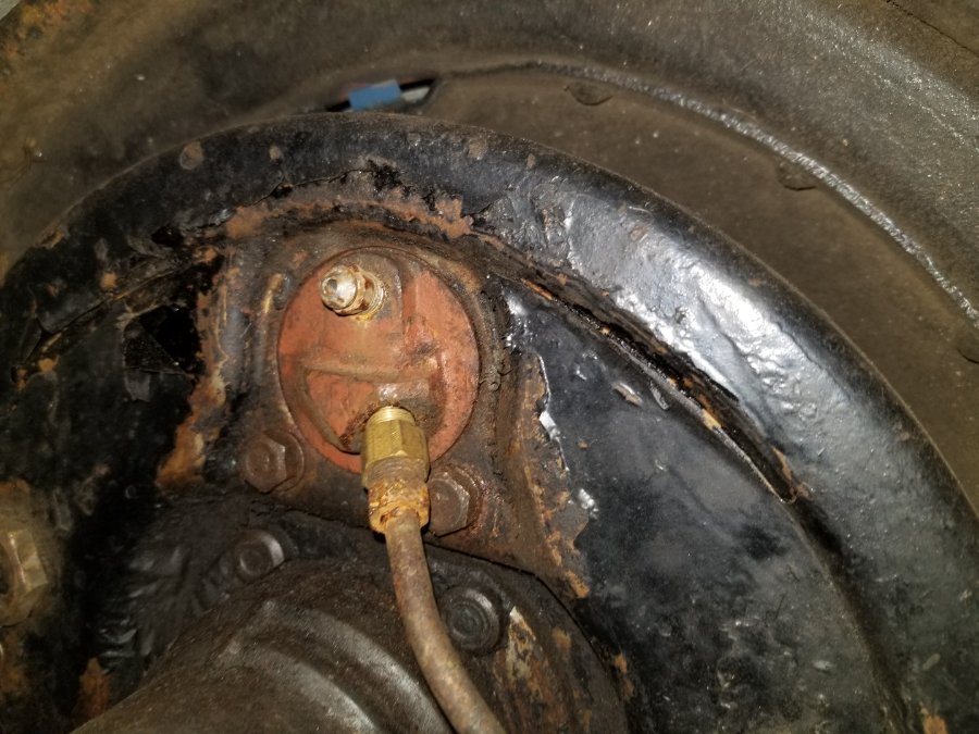
-
Going from memory, I believe my 41 has the brass fittings.
-
Optima battery suddenly too weak to crank on 48 DeSoto!
vintage6t replied to MarcDeSoto's topic in P15-D24 Forum
Regarding the smoke, you should determine why and correct that first. 1. White smoke - burning antifreeze. 2. Blue smoke - burning oil 3. Black sooty smoke - running too rich. As far as acceleration, check all the basics. 1. Plugs are not fouled, see 3 above. 2. You have good spark on all cylinders, especially if only running on a battery. You should use a battery and a manual charger to run with to ensure a strong spark. 3. Make sure your point gap is correct. 4. Set your timing and then re-adjust your carb/idle. 5. Make sure you have no air leaks, carb base or intake manifold. You can read your plugs as well to get some hint as to what the problem may be. -
1949 Dodge Wayfarer roadster inside sun visor pattern NEEDED
vintage6t replied to midcansusp's topic in P15-D24 Forum
Here is a template of the 50 Desoto visor posted above
