


vintage6t
-
Posts
356 -
Joined
-
Last visited
-
Days Won
5
Content Type
Links Directory
Profiles
Articles
Forums
Downloads
Store
Gallery
Blogs
Events
Classifieds
Everything posted by vintage6t
-
...back off piston by turning engine with fan.
vintage6t replied to DonaldSmith's topic in P15-D24 Forum
Sorry if this is obvious or I'm not following correctly, but are you able to move it with the fan belt in its normal direction of rotation, instead of reverse? If so then why not crank until the start or mid of the #1 compression cycle and then just move it forward by hand up to 4 degrees advance? Another thought is that something in the drivetrain is dragging a bit, even in neutral. Try having someone depress the clutch and then try rotating the engine like that. -
Adapting a manual column shift to an automatic
vintage6t replied to vintage6t's topic in P15-D24 Forum
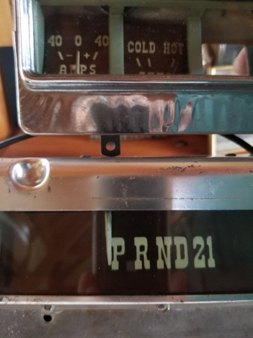
Thank you all for the kind words. I hope this helps others doing non-stock changes. Since I learned a bit on how to go about making a reasonable looking gauge face, I'm going to try doing a voltmeter as well. The car will be 12v negative ground with an alternator, so it will be useful to replace the stock Amp meter with a Voltage meter. We'll see how that one goes, might be pushing my luck. -
Adapting a manual column shift to an automatic
vintage6t replied to vintage6t's topic in P15-D24 Forum
-
Adapting a manual column shift to an automatic
vintage6t replied to vintage6t's topic in P15-D24 Forum
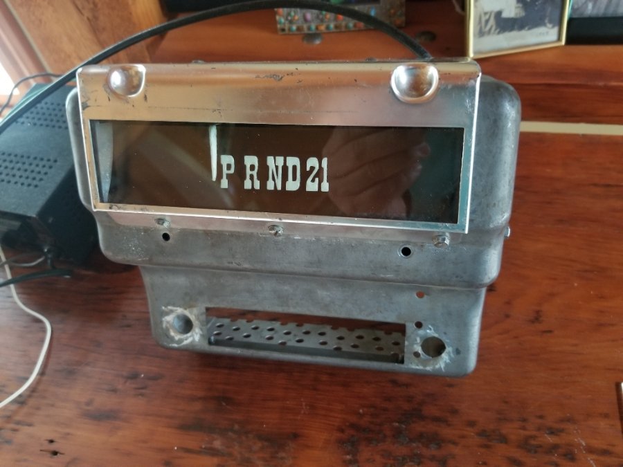
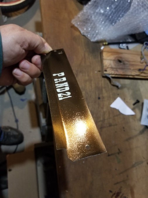
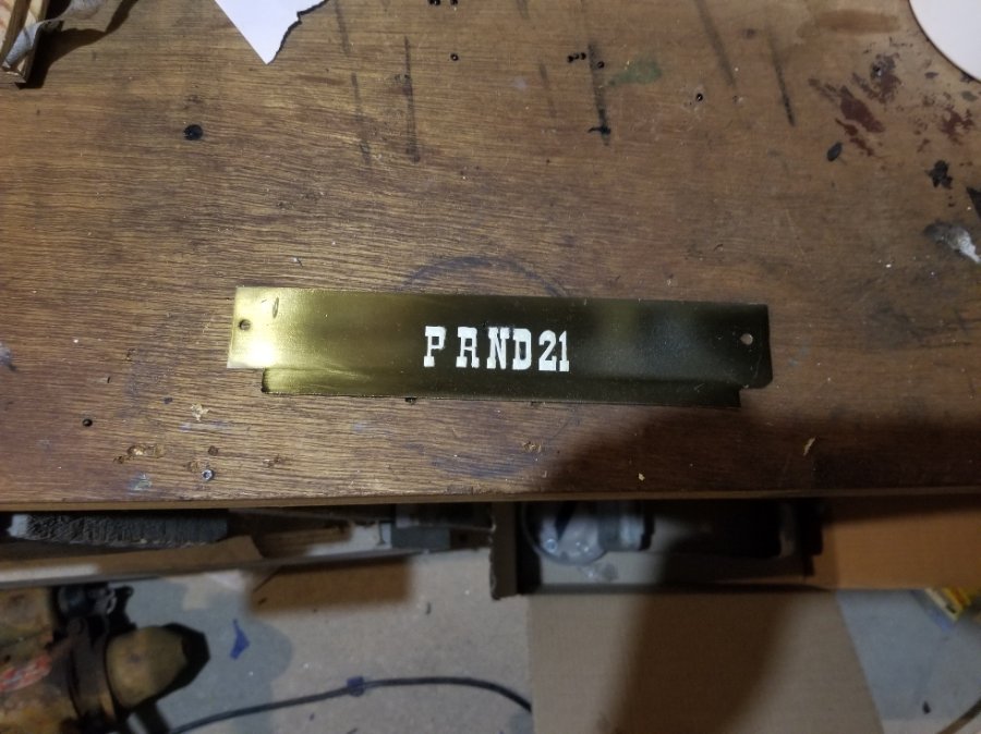
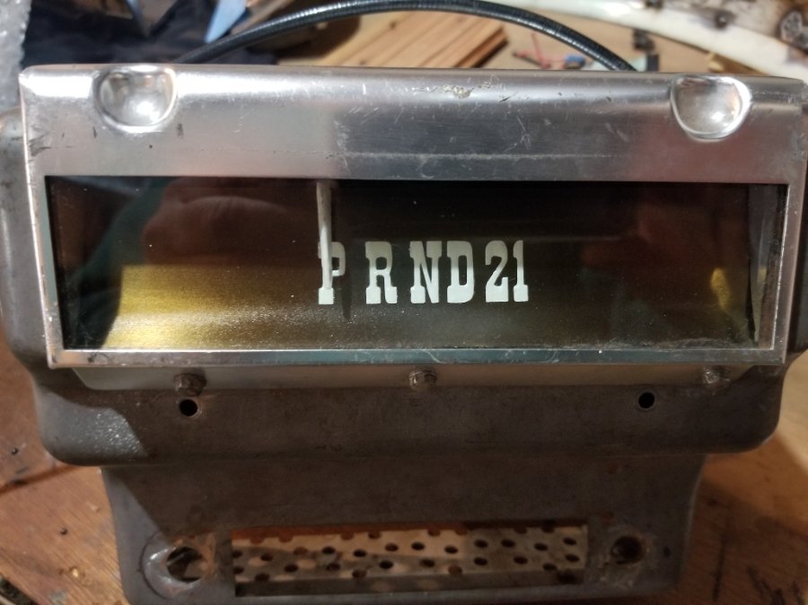
Following up on this project. It turns out the most difficult part was creating a PRND12 face plate to match the factory gauges. After many tries I finally figured it out and made one that matches to my satisfaction. First thing to solve was the faceplate background color. The factory gauges look brown when not in the light. Under light they have a metallic sheen. Starting with a copper blank and many tries of mixed paint color, close but nothing acceptable. Next I tried a brass blank. I also realized the factory gauges are translucent. Almost like antique brass but without color variation, like a tinted lacquer or varnish. The solution turned out to be clear paint very slightly tinted with black paint. Sprayed on with a air brush. Next was the lettering. Many tries here too. Started by hand cutting self-stick stencils used to apply an off white base color and then hand painted phosphorescent green paint. Those tries all ended up looking home made and trying to correct defects all ended up making it look worse. Not an acceptable method. At this point I knew I needed a machine cut stencil. I already new about Cricut machines but couldn't justify buying one just for this project. Telling a friend about this project, it turns out his wife had just one a Cricut in a raffle. So we used my project to learn how to use it. Bottom line, not too hard to create a perfect stencil on the Cricut. Stencil then used to spray on a white base layer for the letters and then hand applied phosphorescent paint on top. Mission accomplished, it even glows the same as the factory gauges!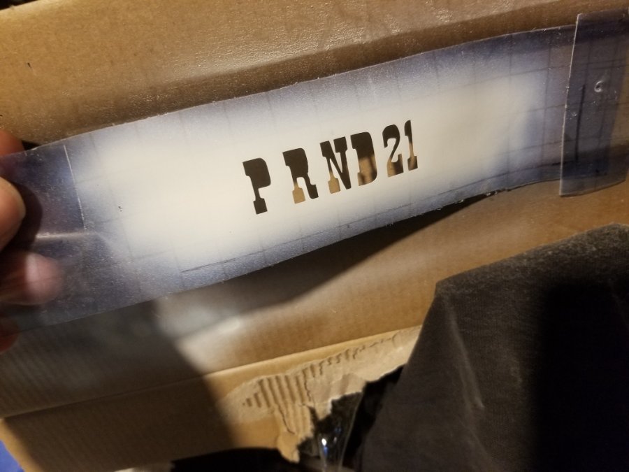

-
Excellent trade! Classic trucks being a hot commodity; around here that truck is worth about twice the value of the car. I know that wasn't the goal in trading but as a bonus IMO you came out on top.
-
Here's one way to mount a booster. Not on the original center line though.
-
https://washingtondc.craigslist.org/mld/ctd/d/chevy-chase-1949-desoto-black-four-door/7610146525.html
-
It's possible your old seal was put in backwards to begin with. Aren't you changing the seal because you had an oil leak from the cover of your freshly rebuilt engine?
-
Using Sniper's diagram above and the AACA guy's seal example, look at it like this; The rubber part of the seal is anchored to the outer metal ring of the seal only on one side. The metal side it's anchored to faces toward the outside of the cover.
-
Are you using the electric pump to start it, or turning it on while driving to over come the loss of power? If only to start, I would suspect possibly a clogged fuel filter or more likely a intermittent clog at the tank pickup. I say intermittent b/c when starting the pickup may flow freely. However, when driving the increased fuel flow in the system may suck debris like rust in the tank and clog the pickup, resulting in a loss of power or even a complete stall. Then when you shut the engine off the debris releases from the end of the pickup and falls back into the tank unclogging the pickup. This cycle just repeats when you drive the car maybe giving the impression it's operating temp related. Could be other things as well but that's where I would start.
-
I think at this point you're probably not going to get the seal out by hammering on it. The cover is probably now a bit distorted and clamping the seal in. The uneven force of a hammer blow is not going to move it. IMO at this point it's going to need even pressure all around the circumference of the seal to get it out. So find a friend or a shop with a press and press it out. Spray it with penetrating oil first and as noted above make sure the cover is supported from the back when pressing the seal out or it will just collapse.
-
Agreed we all have safety lapses. Either via inexperience or b/c "familiarity breed contempt". IMO based on the seemingly endless assembly issues you're having, it looks like you fall into the former. On that note, one thing I see in your videos that is incredibly dangerous is putting your transmission in gear engine running/drive shaft exposed. If you get caught up in the turning drive shaft it will kill you without mercy. You really should make some sort of shield even if it's cardboard. There are countless cases of farm accidents where people get caught up in tractor implement PTO shafts even though they are almost always shielded these days. That's basically the same as you spinning drive shaft.
-
This post got me curious about how they should be laced. All I found was this example of a NOS boot. No laces, just a flap on one side that slides into a sleeve on the other side. Looks like the outer clamps then hold everything in place. https://www.ebay.com/itm/234764658777?mkcid=16&mkevt=1&mkrid=711-127632-2357-0&ssspo=iTHCCyh-Qy-&sssrc=2349624&ssuid=&var=&widget_ver=artemis&media=COPY I guess there were probably laced and non-laced styles available originally.
-
If the engine has sat for a long time, as mentioned above, you may have a stuck or sticky valve on those two cylinders. Try a little Marvels Mystery Oil in the crankcase and see if the rough running goes away after running it a bit. The other thought is bad plug wires on those two cylinders causing weak or intermittent spark. I'd take a look at your cap and rotor as well.
-
I'd be interested to know why they designed the installation to #6 TDC instead of #1 TDC as most engines do. My guesses are something to do with the assembly line process or because #6 is where the plug in the head is for locating TDC. Neither make that much sense to me.
-
How long does a rebuilt flathead engine smoke out the tailpipe?
vintage6t replied to MarcDeSoto's topic in P15-D24 Forum
I think either pipe requires an exhaust gasket to seal the joint -
-
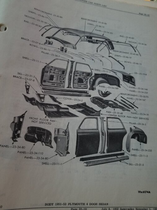
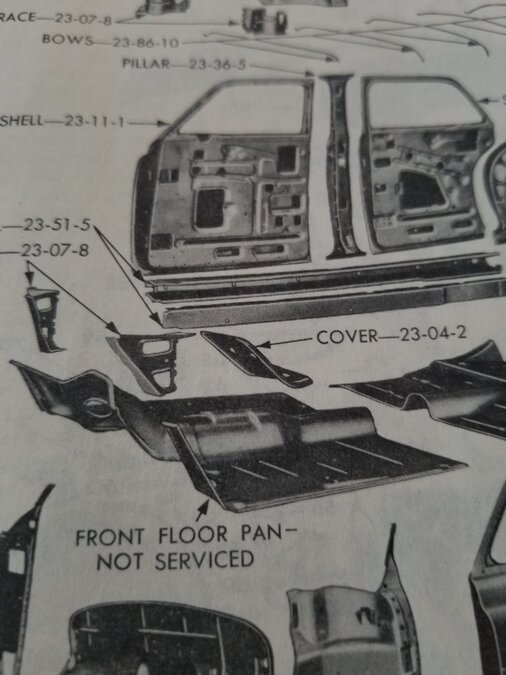
I'm not sure this is helpful but this is for a 51-52 Plymouth 4 Door. Should at least give you an idea how the body is constructed.
-
We'll only you know what makes sense in terms of budget but that step down you originally posted is $119. I would think that's more than enough to buy all the 12 volt bulbs and the small voltage drop components for the gauges, wipers, and fan. I'm not sure you even need to drop the gauges but if you do cheap buck converters will do. You can even skip the wipers and fan for the time being, they'll just run fast. Resistor type voltage drops will work if you don't want to skip those.
-
I don't see that there is anything keeping you from converting to 12 volts with your existing harness. You can always replace the harness later. A 6 volt harness will work fine with 12 volts but not vice-versa
-
You're correct. What I meant to say is if you connect the starter switch to the solenoid terminal that is grounded via generator terminal A and the other side to battery Neg, you'll get a direct short when you press the button. The point is to properly use a remote switch you need to know which side of the soleniod is attached to the car's starter switch and attach it there.
-
According to the diagram, technically on the two upper terminals on the starter there is no such thing as "backwards". You can see in the diagram 1 and 2 are isolated from the rest of the relay circuitry. Those terminals are for the internal relay that close the relay points 3. The relay will work the same regardless of which of its internal coil wired are on 1 or 2. My point is that the repair shop can't really wire it internally for positve or negative. It doesn't matter. The internal terminal connections are dictated by the physical layout of the relay and the length of its coil wires. Externally it also doesn't matter if the car's starter wire is on 1 or 2. The ground to the generator will simply just go on the opposite terminal. Now when you use a remote starter, you better know which terminal is wired though the car's harness to the generator's A terminal and which is to the car's starter switch. One side of the remote starter switch has to go on the same terminal as the car's starter switch. The other side of the remote switch to chassis ground. Otherwise if the remote is connected to the gen A terminal, instead of the car's starter switch side, of the soleniod you'll get a direct short to ground when you push the remote button.

-
I could be wrong about this but I think the side of the soleniod the goes to the generator is the ground. But it's only the ground when the engine is not running. Once the generator starts producing voltage that generator terminal probably goes to 6 volts. That would prevent you from engaging the starter when the engine is running because there would no longer be a path to ground.
-
IMO I don't think the manual shows anything regarding wiring. It is simply showing the the "solenoid switch" unit/assembly. Similar to all the other parts in the diagram.
-
If you use the choke to start and it only smells rich during that time then it's fine. The black on the floor probably due to the same. After all, enrichening the mixture is the job of the choke.

