Earl Gray
-
Posts
24 -
Joined
-
Last visited
Content Type
Links Directory
Profiles
Articles
Forums
Downloads
Store
Gallery
Blogs
Events
Classifieds
Everything posted by Earl Gray
-
Removed resistor on the black wire. No change.
-
@50mech, Great info! This is what I needed! Thank you!
-
@greg g, Though it was frustrating at times, looking back, it makes sense how it wasn't working. You're absolutely right. These transmissions work well and are simple. The transmission issues were operator error. I'm just not too sure if the ballast resistor on the black wire is doing much. My multi-meter didn't read any change. My thinking was to add the ballast resistor to protect the transmission components from 12v when they were meant for 6v. Overthinking or underthinking? I'm going to test: 1. Both black and green with their own ballast resistors. 2. Both without the ballast resistors ...and provide an update. I'm sure someone else out that's more knowledgeable and experienced then me can jump in about the placement and effectiveness of how it's currently wired.
-
Flathead to Slant 6 distributor conversion...
Earl Gray replied to thrashingcows's topic in P15-D24 Forum
thrashingcows, Thank you! I've been looking through your photos. Very helpful! Thanks for taking the time to post them and thereby, help others! -
What are you using for a replacement horn relay when you can't find OEM/NOS?
-
Very helpful. Thank you! I disconnected the battery many times while trying to get the wiring right (cross-referenced post below) that it most likely reset it then. Good to know a solid solution. Thanks again!
-
Do you have a gyromatic D-42 converted 12v with productive information or are you just the forum police?
-
You didn't seem to have an issue finding both.
-
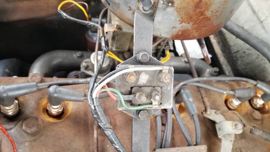
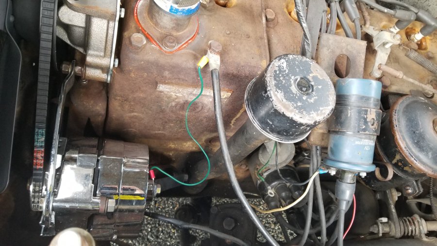
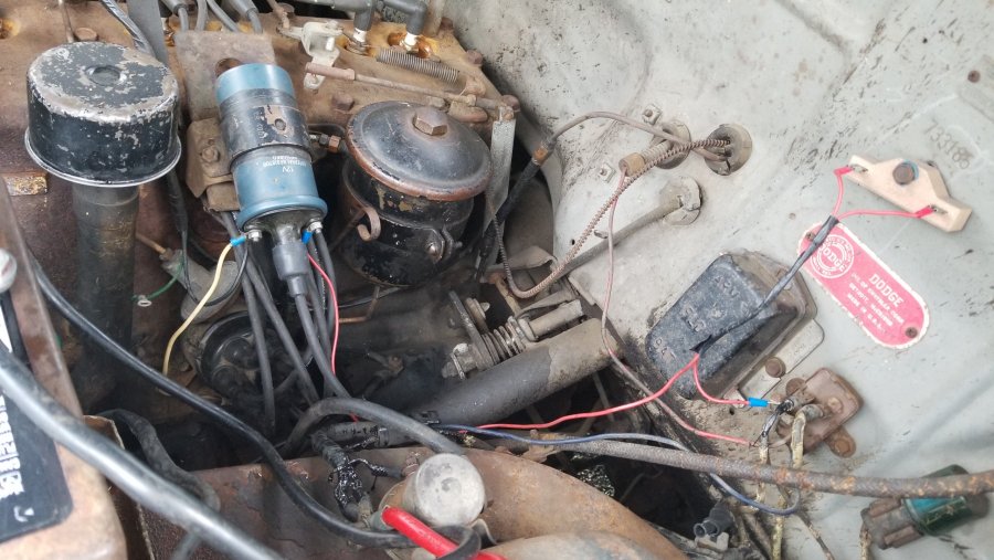
Final analysis and solution: For a converted 12v D-42 with a Gyromatic, the black wire needs to be connected to the negative ignition coil post and the green needs to be connected to the positive ignition coil post. The black wire goes to the Interrupter Switch. The green wire goes to the governor. When I wired according to the service manual (black to positive and green to negative) it killed the coil. When I rewired it (switching black/green as stated above), everything worked. When black and green were wired wrong, it grounded out the blue interrupter switch, which when done as a resistor test, kills the engine (see photos and alligator black test wire alligator clipped blue terminal to block ground). Additionally, wiring it wrong made the transmission act like the handbrake was engaged when it wasn't. When this happened, I returned the wiring to base line (only black on negative post and green was hanging free) to get the transmission "unstuck." The "stuck" acting transmission probably happened by the overload to the governor, since the grounded blue only kills the engine/ prevents it from starting. I'm not an expeat but I've learned along the way and it's running well. If you have experience with this, please drop a comment.


-
Update: After hours of different tests and configurations, here's what I have. I switched the black and green wires coming from the ignition coil and added a resistor. Black is on the negative coil post and green is on positive coil post. Works great, shifts well, doesn't stall, and the kickdown works great too. I was hoping to find someone with a D-42 with a 12v system and gyromatic to see how they have theirs running in the proper configuration. Hope this helps the next person. If there's any issue with this current configuration, I'll give an update.

-
I appreciate your feedback and suggestion.
-
'51 Coronet (12v) won't move forward. It acts like the handbrake is engaged when it's not. Is there anything electrical that makes the transmission act like this?
-
UPDATE: I switched the wires coming from the carb to the coils to black on negative coil post and green on positive coil post. Engine starts and column shifter switches between gears but the transmission acts like the hand brake is still on. Yes, the actual hand brake is disengaged.
-
You're on to something. I disconnected the black and green wires that go to the circuit breaker/resistor unit and it started. It's running right now. I'm parked outside my house and typing this as it runs. Now what? I'm going to run a resistor from the coil to the carb. I'm still not sure which wire going to which post. Before the issue...Black was connected to the negative post and the green was hanging free, no connected. I connected them according to the service manual and had the issue. I disconnected them both and the car started. Since it's been converted to 12v, it's no longer a positive ground, so the negative post now connects to the distributor. That being said, does the black and green wires switch now too, i.e., black now needs to be connected to the negative post and green to the positive?
-
Maybe. but what about the black and green wires? Do the black and green wires switch posts too? If so, how does this affect anti-stall, kick-down, and other components for the carb and gyromatic?
-
No. I rewired it back to what it was before the issue and no spark.
-
-
-
-
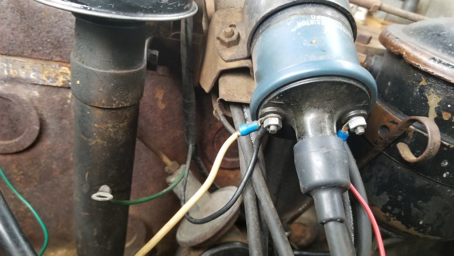
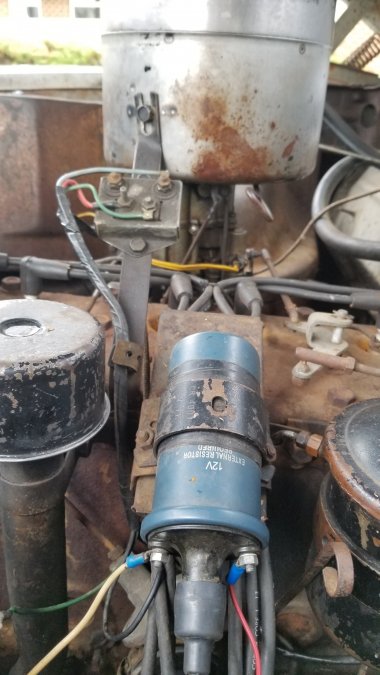
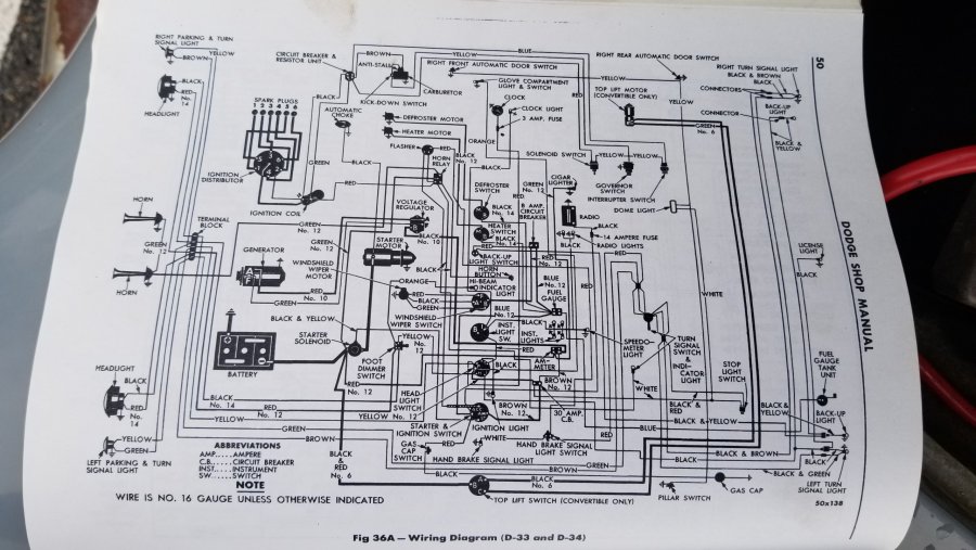
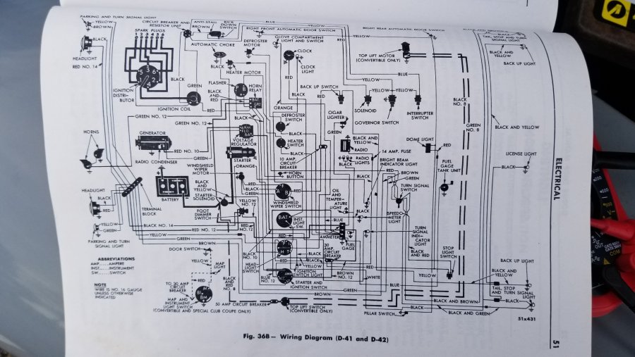
UPDATE: 4/11/20 Final analysis and solution below. _____ Original post: I have a '51 Dodge Coronet (D-42) with gyromatic that's been converted by the previous owner to 12v with one-wire alternator. If you have a link to a previous post about the issue/questions below, please share. Issue: No spark from 12v ignition coil (with required external resistor in place and properly installed). What happened? When I got this car, there were some wiring issues. My car stalled/died at a stop due to the transmission downshift. According to the late and very knowledgeable Don Coatney's pictures, he wired his ignition coil (-) to distributor and (+) to external resistor/power. Here's the link to his pictures: https://smg.photobucket.com/user/DonCoatney/media/Engine/dimple.jpg.html?sort=3&o=80 When I bought the car: The black wire from the circuit breaker/resistor unit was connected to the ignition coil's (-) post. The green wire from the circuit breaker/resistor unit was not connected to the ignition coil but just hanging out, not attached to anything. Just today, I connected the Black wire to the (+) ignition coil post Green to the (-) ignition coil post And it did what it was designed to do...didn't stall/die at a stop and shifted way better then before. Then...a few blocks from home...it died. No spark at the ignition coil center. The Dodge service manual has four different wiring diagrams: For the D-29 For the D-30 For the D-33 & D-34 (photo 1) For the D-41 & D-42 (photo 2) The first three wiring diagrams in the service manual have the same details regarding the ignition coil: (+) to the distributor and (-) to firewall (horn relay?). However, the wiring diagram for the D-42 doesn't show the ignition coil's polarity for some reason (see photo 2). Also, regarding the circuit breaker/resistor unit, the black wire is shown in the diagram to connect to the (+) post and green to the (-) post. That's why I did it this way. Again, when the black and green wires were connected as mentioned above, the anti-stall worked perfectly and it shifted way better. Amazingly so! I need to buy a new ignition coil. I'd like one that doesn't require an external resistor like the NAPA Part# MPE IC14SB (Thankful for grey beard's suggestion from January 1, 2010) Questions: Is it required to switch the ignition coil wiring to (+) wire to (-) post and (-) wire to (+) post when converted to 12v? Do the black and green wires switch too? If so, how does this affect anti-stall, kick-down, and other components for the carb and gyromatic? What horn relay replaces the OEM?
-
Great points here too! Thank you both!
-
Great points here! Thank you.
-
Good question. Unknown. I didn't convert it to 12v.
-
Joined last week. First post. I own a '51 Dodge Coronet (230cu in, converted to 12v, one-wire alternator) with a Gyromatic. The issue is, when shifting from low to high, it will not shift to 3rd. It only goes from 2nd to 4th, confirmed by coming to a complete stop and it downshifts to 3rd. In fact, when it downshifts to 1st or 3rd at a complete stop, it almost kills the engine. The kickdown doesn't seem to work either. The Service Reference Book for trouble shooting the hydraulically operated transmission says when "the car speed is down, so the governor points are closed and the circuit through the solenoid is completed down to ground. That means that the solenoid plunger is down, holding the ball valve down off its seat." What I've done before creating this topic: Flushed/replaced fluid in GyroMatic according to service manual. Adjusted idle to 450 - 500 rpm range. Adjusted dash pot on carb to meet service manual specifications. Shifted from 2nd to 3rd (low to high) at service manual's recommended speeds. Searched this forum for specifically related issues and read through many. Just for the info, most gyromatic photos show the interrupter switch in the spot towards the vehicle's front and above the governor. My interrupter switch is towards the back of the gyromatic and above the solenoid. Is there some reason for this besides different year/model? Note: If you know of a specifically related thread (shift from 2nd to 4th only), can you please provide a link?