

PT Moe
-
Posts
30 -
Joined
-
Last visited
Content Type
Links Directory
Profiles
Articles
Forums
Downloads
Store
Gallery
Blogs
Events
Classifieds
Posts posted by PT Moe
-
-
Bob, Thank you so much. That is great help. Really appreciate your taking the time to post the pictures.
-
PT125 fuel line.PDFPT125 fuel line.PDF1941 Ply PT125. Got my rebuilt flathead back in the frame and am now trying to figure out my gas line routing. Looking at pictures I took back in the late '70's when I took the truck apart I think I got it somewhat figured out but would appreciate any verification. Looks like it comes out of the tank and goes through a riveted clip under the frame just behind the battery, Up along the outside of the frame through another riveted clip and up over the front shock mount to the front of the frame crossmember that supports the motor mount and turns back on the passenger side to a flex line at the fuel pump. Does not look like much room at the bottom of frame crossmember with the harmonic balancer and the radiator support that bolts there. Also, the line was spliced part way with copper so it may not have been routed as original. Running 5/16 NiCopp line. Thanks for any help. Jeff
-
Never deleted the link for Vic's and I happen to click on it today. Was surprised to see they will be reopening soon under new ownership. Lot's of their stock is back online.
-
 1
1
-
-
I'm glad I got mine last year, but that is good news.
-
Yes I see a lot of places sell them online. They do show them as Disc/Drum or Disc/Disc so I would think the Disc/Drum would be set to go. Ebay or Amazon seem to be the best prices. Do you recall where you got yours with the bracket? Thanks, Jeff
-
Trying to get all the brake stuff for my '41 Ply figured out. I have the Scarebird front disc kit all mounted and am pretty happy with how that went together. I went through all the threads here on the subject and gained a lot of knowledge and thank everyone that shared info on this. I have gained an understanding of the concept of the 2psi residual valve for the front and the 10 psi on the rear, the combination valve and the adjustable proportioning valve. I'm thinking of using this dual MC from DCM. https://dcmclassics.com/brake-parts/1438-br-780-master-cylinder.html Looks to me like the Toyota one people here have used. Still trying to figure out all the fittings and stuff but I'll take that one step at a time. I think this photo posted by lostviking is a helpful starting point for me to go by.
Also, I found this writeup and diagram which helps me to understand how it all goes together. Any thoughts or ideas are appreciated. I'm a retired carpenter so this stuff is all new to me.
http://www.how-to-build-hotrods.com/brake-system.html
Thanks to lostvikings for this photo.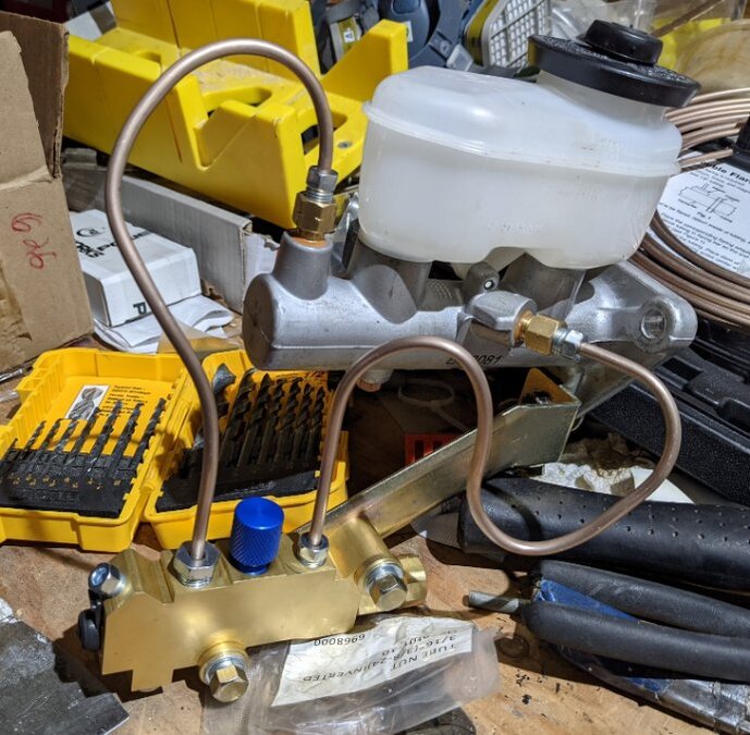
-
10 hours ago, bkahler said:
THAT is a scary unloading operation

Just doesn't look stabile enough for me.
Sure is, and the next one he has to back down. Yikes!
-
I think DCM sells the right bolt for that. Pretty short so it don't hit the hinge when closed. Looks like a 5/16 fine thread.
-
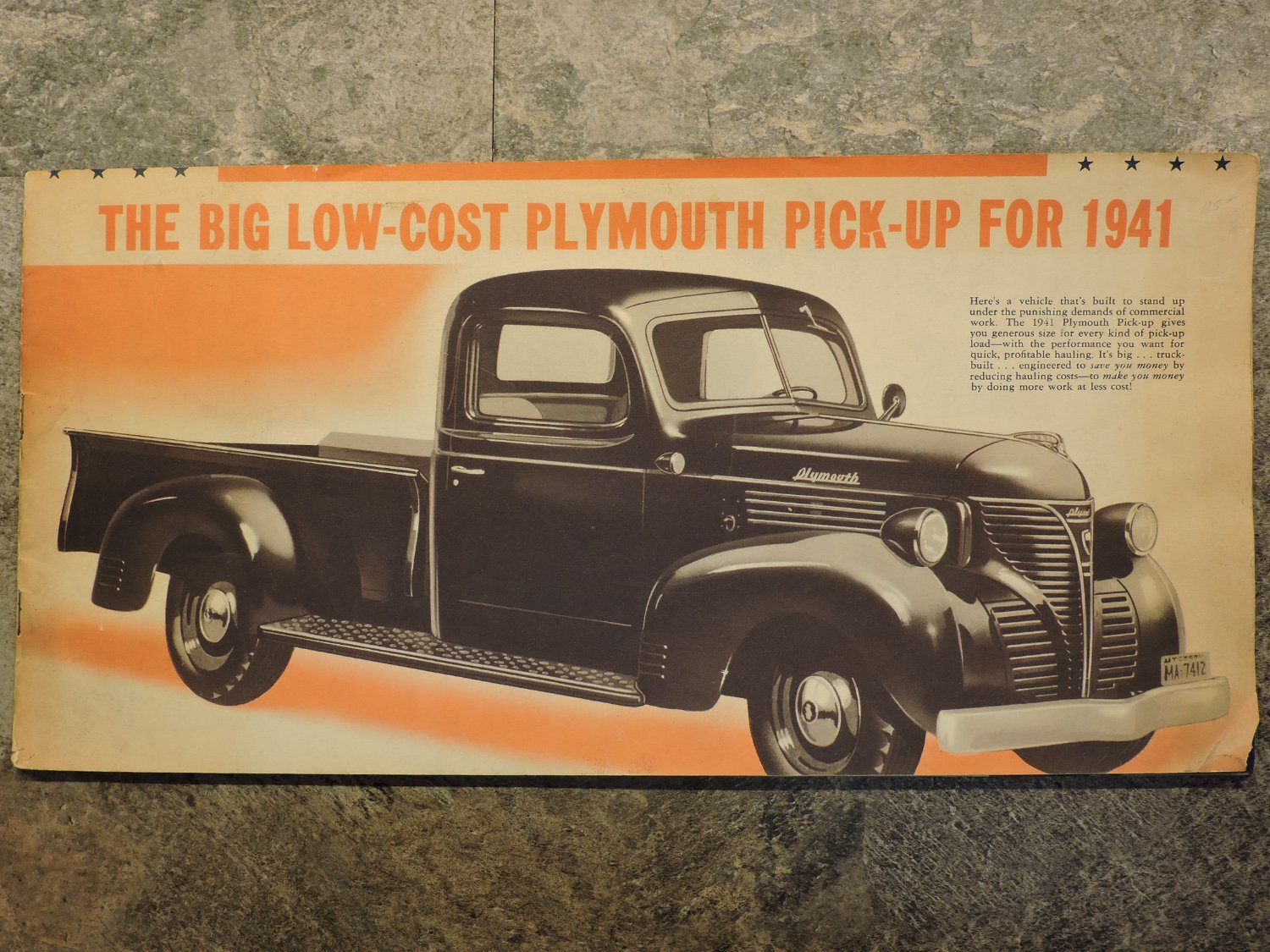
Found this laminated ad at a thrift shop.

-
Being a retired carpenter by trade I did my own. The bolts and screws are 8" apart starting center. I bought 1x10 white oak and ripped it to 7 1/2" to give a little gap between the bolts and the boards. (1x8 being only 7 1/4" is not enough). I got my bed strips from Vic's (now closed) cause they claimed to be like the original type with the combo of square and countersunk holes. Square for carriage type bolt between cross members with washer below and countersunk for screw into cross members. I'm thinking of putting a screw or two from under the cross members up into the boards to help keep the centers down tight to the cross members. The remains of my rotted front bed panel show a carriage type bolt centered in each board and through the bottom flange of the panel.
The bed strips are 1 1/2" wide so I dadoed the edge of each board with my table saw 7/16" wide by just over an 1/8" deep. 7/16 plus the 1/2" gap between boards gives about an 1 5/8" space for the strips so there's a little room for movement and expansion. I did not do the extra little kerf where the edge of the strips run but the strips I got are pretty flat across but I'm thinking I might just do it so the edges of the strips don't rub the finish off the wood. The 2 outer boards that go under the bed flanges on the side panels are only dadoed on one edge. You want the full 3/4" thickness there on top of the 2" high cross members.
After doing some research and not wanting to use an exotic imported species for the floor boards I decided on white oak. Although it is similar in appearance to red oak it is much more stable and resistant to decay, not that that makes a big difference on a truck that will not be sitting out in the weather. White Oak is also slightly double the cost of Red Oak around here so I hope it was the right move. 6- 7ft 1x10 boards cost me a little over $500.00.
Pictures are a dry run before I take them back off to seal and finish. Thinking of stain with a clear sealer over that. I found a gel stain at Home Depot that is exterior rated and can also be top coated with a water borne or oil base clear finish.


-
As ggdad said bend them in a vise or other method. Not sure how the '48 mounts but on my '41 I removed the hinge from the cab and layed it on a steel plate on the floor and wacked it a couple of times with a small sledge hammer. Took a few tries to get it right but doors fit mint now.
-
Here's a picture of my '41 Plymouth from back in the mid '70's when I started taking it apart. Shows coming out the firewall and a clip screwed to the firewall below the heater hoses.

-
With the elongated holes in the brackets you might want to take note or mark how everything lines up so there is less adjustment work to do reinstalling in a newly painted cab.
-
That is a beautiful truck. What did you use for wood in the bed? I like the black finish also. I priced out white oak as a possibility for my '41 and that stuff is up there. $13.00 ft for 1x10. Engine looks great too.
-
I have the same part and wondered the same thing. The holes matched the mounting bolts on the gas tank but I just could not figure out how that would work. My truck is finally going back together after I took it all apart over 45 years when I was much younger and stupider too. Another mystery solved.? Learning good stuff here.
-
I was just going to ask what the little button above the speedo was. Got a hole there in my dash that definitely looks factory but no fitting so now I know. Thank you Young Ed.
-
The picture PT81 shows is what your looking for. That small welt stuff is for the front against the lower nose section and the rear fenders.
https://dcmclassics.com/dust-and-air-seals/232-rw-100-front-fender-filler-39-47.html
https://vicsdodgegarage.com/product/34-47-dodge-r-l-fender-to-cab-seal/
https://vicsdodgegarage.com/product/34-47-dodge-r-l-fender-to-cab-seal-rivets-10-each/
Roberts picture isn't real clear.
-
Checked mine, tough spot to measure. It's just under 3/4" on my stock 16's. I took a piece of 3/4" thick wood on top of the caliper and it almost fit between but hit the wheel. Doing mine I did notice that the Lincoln rotors in the instructions are a little bigger that the Ford Probe rotors they state on the web site. I didn't use any wheel spacers. Looks close but you might be ok but I would check with Scarebird.


-
I just put them on my '41 with 16" wheels. Instructions called for Lincoln MK VII rotors and Chev Celebrity calipers. I'll check clearance with my 16's tomorrow and you can judge from that for 15's.
No plumbing work on mine yet. That will be a head scratcher for me.
-
There is some room for adjustment in the hinges. If the tops not tight also should be able to bring it in some.
-
I really appreciate all the information I been getting from this forum. Took my '41 apart many years ago when I was young and stupid and lost a lot of the notes I wrote down. Retired now and trying to get the project finished. Fallowing this thread I finally realized where the 2 little bolts with the springs on them go. They would have been in the "Ain't got a clue where they came from box" forever.
-
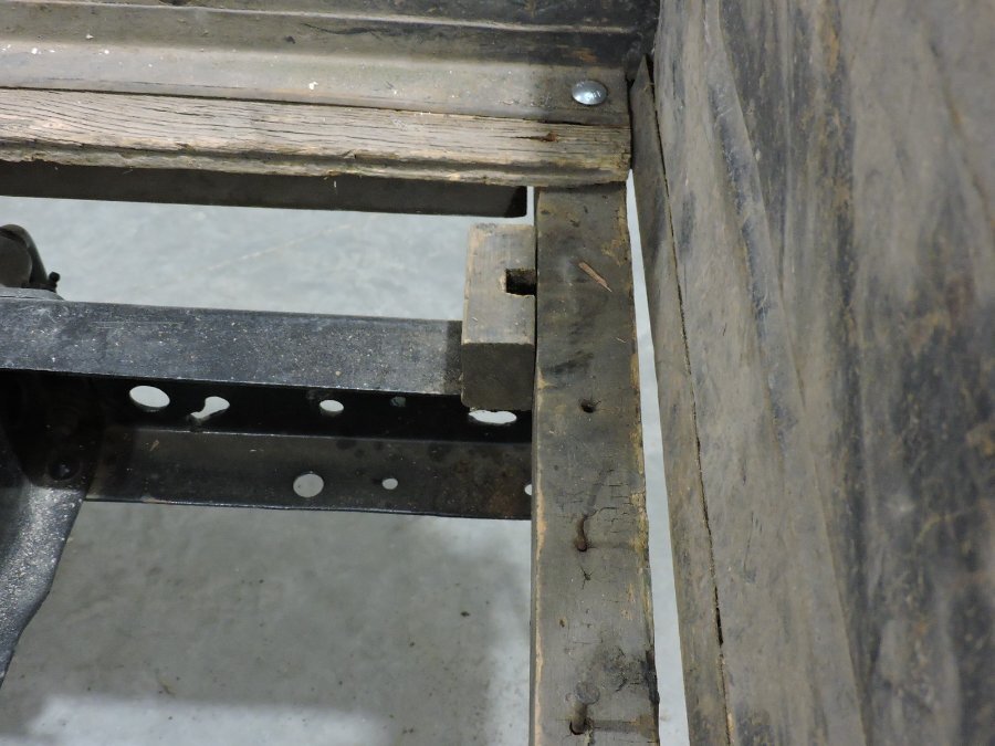
Here's a few more pics. The lower bolt for the tailgate hinge goes through the cross member and stake pocket. Upper hinge bolt goes into a factory set nut inside the stake pocket which is rusted out on mine. Another bolt goes from under the cross member vertically up into a factory set nut in the bottom of the stake pocket. that's rusted out on mine also. Picture with bed side panel lifted up shows rear cross member cut at slight angle or curve to fit the contour of the outside of the stake pocket.
This trucks been apart for many years and I saved everything. It's time to finish it now so I fitted everything together so my body guy can see what he's working with before I take it back apart and give him all the pieces.
I certainly don't claim to be an expert on this stuff but have been able to figure out how it all goes together pretty good with what I have. Also, just got my engine back this week from the rebuilder and he had it running in his shop before I picked it up so I'm pretty pumped up about getting this project done.


-
I have the remains of mine from my '41 1/2 ton. I'm pretty sure my back one is original but not sure about the others. They all measure 2 in. tall x 1 3/4in wide x 48in long. The back one is about 52 1/2 in +- to extend into the bed panel stake pockets. The back one also extends off the frame ends about 1in. My back one is a solid board but but the others are made up of 2 boards fastened together. Not sure how they came from the factory. Looks like they sat on some kind of reinforced rubber pad 1/8in - 1/4in thick.
DCM sells them as a set.
Working in construction pressure treated lumber and metal did not work well together. Always used a membrane between them to prevent corrosion. I would not use it myself.


-
The color chips I got are much too small according the them.
Vintage picture thread
in Mopar Flathead Truck Forum
Posted
I see Kermit in his Studebaker.