

Vet Doc
-
Posts
71 -
Joined
-
Last visited
-
Days Won
3
Content Type
Links Directory
Profiles
Articles
Forums
Downloads
Store
Gallery
Blogs
Events
Classifieds
Everything posted by Vet Doc
-
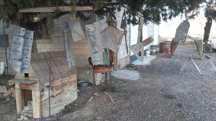
Fortunately, I don’t have many neighbors and it’s not very visible from the road. Passersby might think I have a strange wind chime collection or Shaman spirit tree. We all know it as the doghouse inner support pieces prepped for painting. It was the first day weather has been cooperative for outdoor work.
-
ANSWERED Sheet metal identification
Vet Doc replied to Vet Doc's topic in Mopar Flathead Truck Forum
Thanks for the identification and explanation of mounting! I went out and with the information provided, it makes perfect sense. Just need cleaned up, painted and installed. -
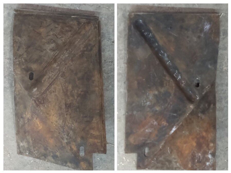
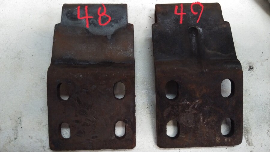
I am working on body work on the front clip and have run across a couple of pieces that I can’t identify or figure out where they belong. I hope that somebody recognizes them and can help me out. I looked at my parts pickup and can’t find them. The views are front and back of each and I hope they are clear enough.

-
That’s what I was searching for—-Thanks!
-
Thanks for the work! I’ll keep watching for updates.
-
I recall seeing the parts manual on the DPETCA site and tried to find the information on way back, but, as previously reported, a lot of the pdf files don’t appear to be available. Does any one know where they might be found? Specifically, I was looking for the body/sheet metal pages and diagrams.
-
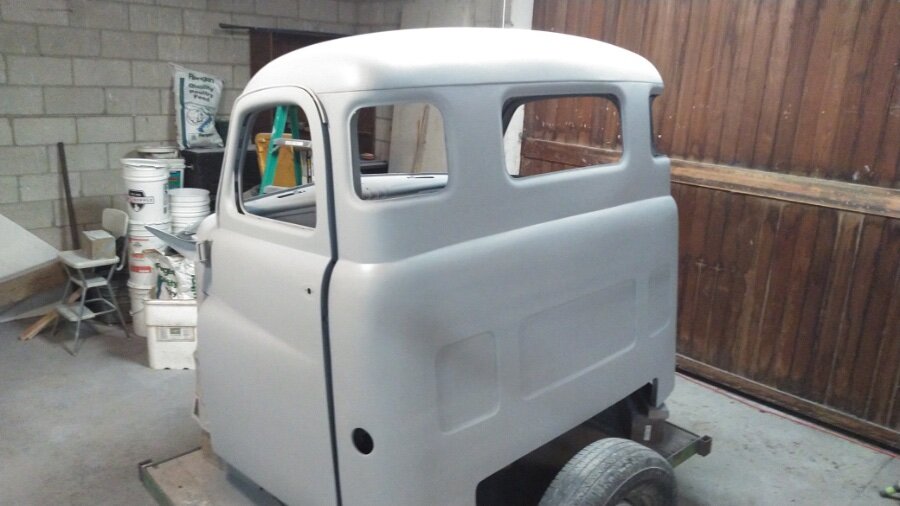
Primed and ready to block it out. Need to start looking at cab rubber and glass options.
-
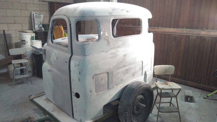
It’s been a while since a post, but after a lot of cutting, welding, metal grinding, beating, and a little body filler, ready for high build primer. If we can get the cab done, we can move to the front clip. Probably getting ahead of myself, but the interior cab liner from Quiet Ride and the wiring harness from Rhode Island Wiring is ordered, too.
-
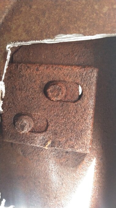
I came to that same conclusion and after sacrificing a drill bit, was able to drill and tap out the existing plate. I was just hoping that someone had come across a trick that was easier than what I could come up with. For curiosities sake, I opened the back of the pillar on my donor pickup and made the pictured discovery. The screws (1/4 inch diameter with fine threads) are in the picture taken from the back of the pillar. The screw plate resides inside a box welded into the front of the pillar with slots that match the exterior front side of the pillar. I figure designed by an entry level engineer with a grudge against accessible maintenance procedures…
-
Thanks for the info—I should have clarified that I am referring to the catch on the B pillar. Coincidently, I used the referenced post when I rebuilt the check and added my modification.
-
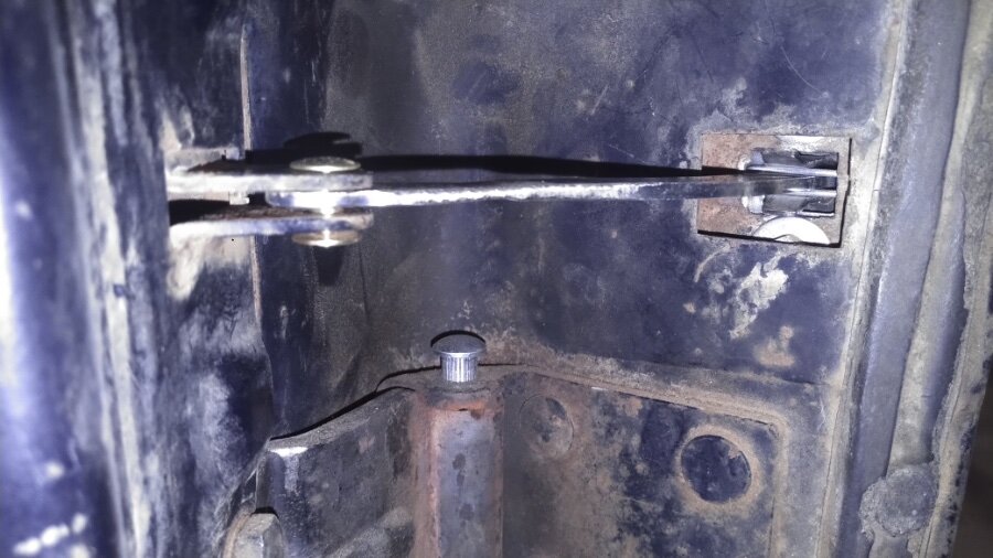
I am curious if anyone has any experience with the piece that is on the inside of the pillar that the door catch screws into. It appears to slide left and right for adjustment purposes and, as far as I can tell, is enclosed inside the pillar on some kind of channel or tabs. I need to replace my driver side because the bottom screw is broken in the threads. Figured I would reach out to anyone who might have already been through this and might have any suggestions on the best way to proceed. Otherwise, I’ll cut a hole in the back of the pillar to see what kind of channel the backing plate is sitting in.
-
Door Check Retainer Replacement for Pilot-House Cabs
Vet Doc replied to JBNeal's topic in Mopar Flathead Truck Forum
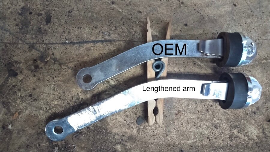
Working off of JBNeal’s fix and door check source, I thought I would add my adaptation. Thanks for sharing the information and inspiration. Fortunately, I had the door off of the cab and stripped of pretty much everything allowing access and mobility. I was able to leave the exterior of the door intact by working through the access panel to place clip portion of the check internally. After drilling holes on the inside door panel, I threaded 1/4” x 3/4” bolts through the clip plate. Fishing a lock washer and nut onto the bolts between the exterior and interior door panels took some patience, but it wasn’t too bad. Tightening the nuts as much as possible, I then moved to the inside of the door and backed up the bolts (threaded into clip mount) to tighten the nuts against the interior door panel. With the OEM replacement check bar, I too noticed the door didn’t open as much as much as originally intended. Since I had the limiter arm from the Chevy replacement, after measuring how much longer the check needed to be, I cut the hinge end off and added just under an inch to the arm. It now opens to the original angle and doesn’t seem to interfere with anything internally on closure. I am very happy with the outcome and again thankful for the previous information in the post.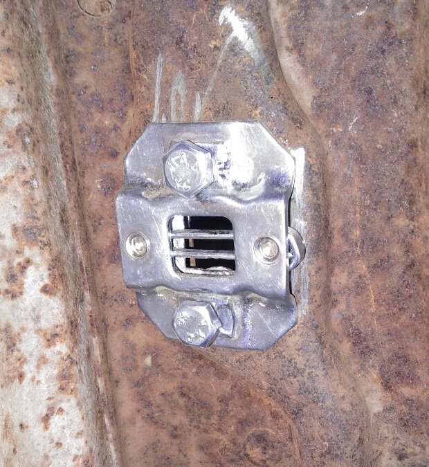
-
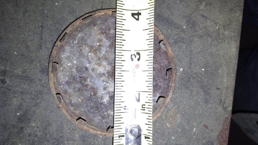
I found 2” metal hole plugs on Amazon as a pair, relatively inexpensive and figured it was worth a try since the original caps were pretty well rotten. The fastener tabs are shorter, narrower and with more of them, but with a little adjustment of them, they seem to push in relatively tight. I don’t know how much vibrating they will take, but I had to pop them out with a screwdriver.

-
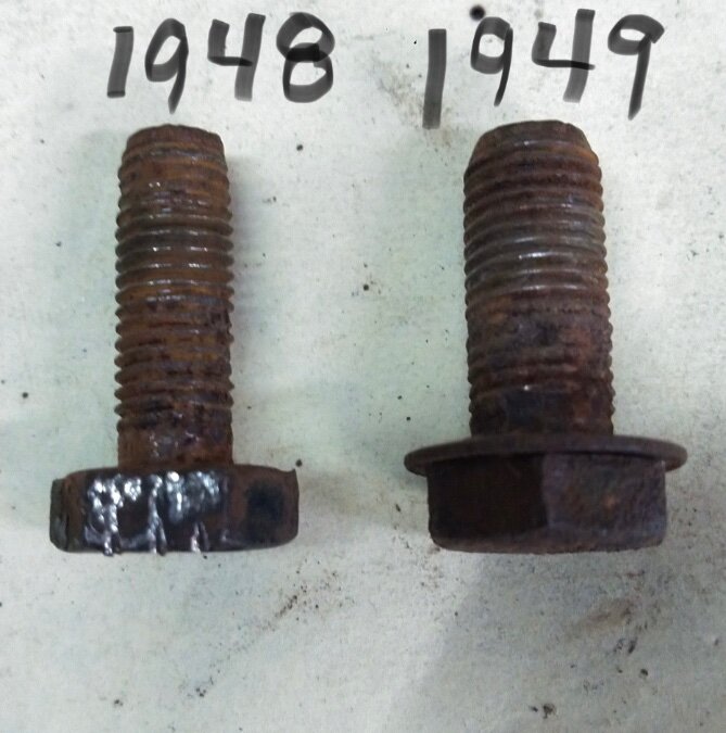
During mixing and matching door parts, I discovered that the hinge bolt diameter changed from 5/16” to 3/8” from ‘48 to ‘49. Both have 9/16 heads and 24 tip fine threads; the hinges have matching slot diameters. Also, the ‘49 hinges have been stiffened with a pressed bend in the center of the metal. I am considering using the ‘49 hinges because they should be stronger/stiffer, but I’m not sure how the bolt diameter and slot size difference will affect functionality. In theory, there should be more adjustability, but there may be more sloppiness for the bolts to keep the adjustment secure.
-
Started working on the cab door hinges today and discovered that the bolts differ between 48 and 49 that hold the hinge to the pillar. The bolts from the 48 are 3/16” NF with a 9/16 hex head and the 49 are 3/8” NF with a 9/16 hex head. Didn’t realize it until I went swap some out from the donor and didn’t fit. No luck with the local hardware store for the large headed 3/16 bolt, but I’ll see how a half inch head might work or what I can find on the internet.

-
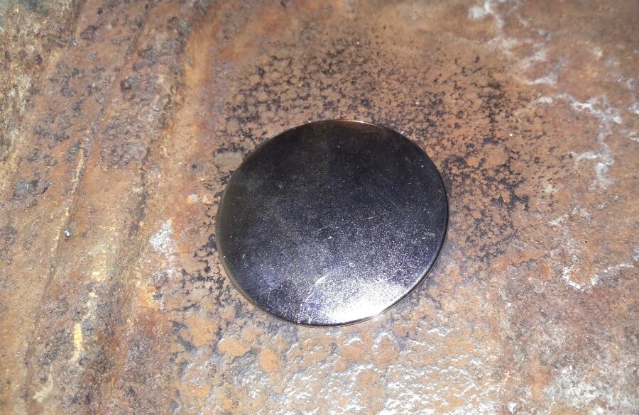
After welding in floor, patching holes, and remanufacturing some pieces, the floor is roughed together. Surprisingly, the pieces appear to match up well. Now I can take it apart, clean it up, and get the metal sealed up. Close inspection will reveal that I found my ‘easy’ fix for the previously discussed knock out hole. I am a little embarrassed to admit that I hadn’t looked very closely at my donor cab for its fuel tank access cap. Sure enough, it was there buried under about two inches of dirt, old seat cushion remnants, and various unidentified debris that somehow managed to preserve it. Thankful to live in a desert.

-
The section that I originally removed has a very rusted knockout that was about 50% intact (‘48 B1 cab). The section that is welded in came from a donor cab (‘49 B1) and was petty much as appears in the picture (minus some wire wheel brushing) without a knockout or cap present. Because the donor piece of floor had comparatively minor rust, I assumed that it had a cap that had just been lost over time. The only other floor difference I see between the two is the emergency brake setup. The ‘48 is a hand lever through the floor and the ‘49 appears to be a handle on a cable through the firewall. Maybe an adjustment access for the cable hand brake?
-
That’s what I was considering, but thought it would be awful handy just to pop in a cap. I can’t figure out what it might be an access for that couldn’t be reached from underneath.
-
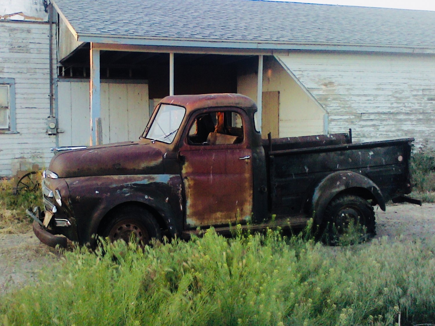
Obviously been a while since any updates, but it has been a long couple of years since Ernie’s first time in the road since 1961. That said, I have been spending most of my shop time working on body skills. There isn’t a straight piece of metal and significant rust and body damage throughout, so I have been hammering, cutting, welding, grinding, etc. (Once I built up the nerve to start). During the cab reconstruction, I noticed the two access holes (blue arrows) in the floor. The one under the seat for access to the gas tank float had a cap (red arrow) covering it. The cap for the access hole in front of the passenger side (welded in from a donor cab) was non-existent. I assume that since the holes appear to be the same size, there was the same cover, but I haven’t been able to confirm that or find a source for that cap. I have found some plastic and rubber caps, but no metal caps that diameter. Any suggestions would be appreciated.

-
Covering general safety procedures prior to embarking.
-
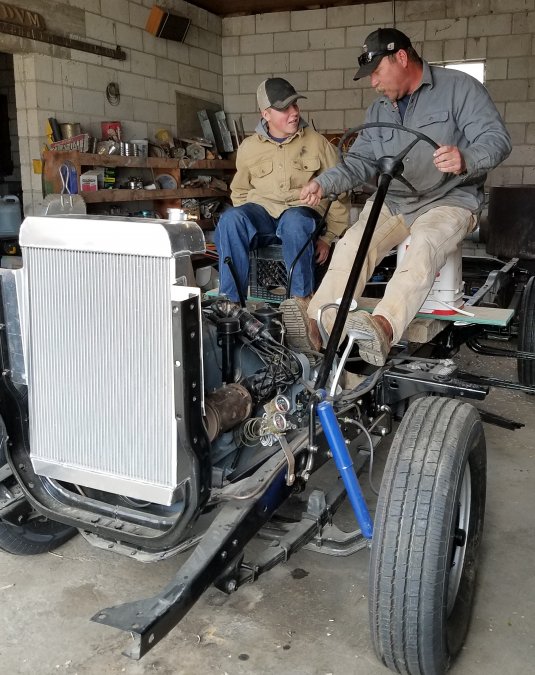
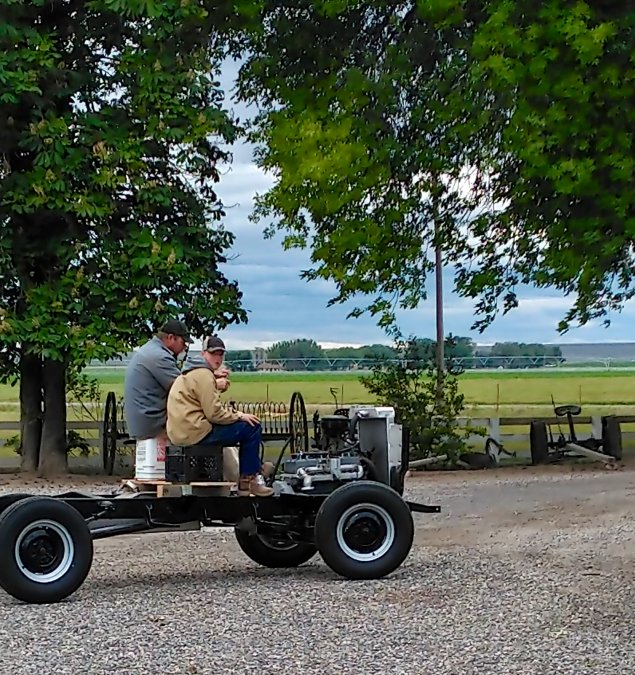
Got tires mounted, adjusted the brakes, secured the battery, covered general safety procedures, and headed out for the ‘open road’ with my youngest son this afternoon. First time Ernie has moved under his own power since 1961. Drove down the road a couple miles, worked on another farm truck, and came back home with no major issues. Good thing we live in rural farm country where this kind of thing is relatively normal.
-
Between the eight 16 inch wheels I have for the B1B, I narrowed it down to five for use. The three I opted not to use were bent, welded, and generally unsafe. Of the remaining five, two are 4 1/2 inches wide and three are 4 inches wide, measured on the inside of the wheel. One of the 4 inchers appears to be a “safety” wheel design. i admit I didn’t check the width prior to sandblasting and realized it when I went to finish prepping for painting. I was planning on 215/85 R16 tires, using the safety wheel as the spare. Any thoughts or suggestions of which wheels should be mounted on front vs. rear?
-
It would appear that there is at least another ‘48 B1B in Idaho. Mine was originally in Fruitland at my in-laws farm where it had spent it’s entire life prior to 3 years ago when it moved a little to the southeast.
-
Rear aspect of left front. Let me know if you need a different angle or view and I’ll se what I can come up with.

-
Front aspect of left front.


