Leaderboard


Popular Content
Showing content with the highest reputation on 02/03/2021 in all areas
-
I am with sniper, I find myself resisting the urge on price but, not on the year or size. don't list your 1 ton as a 3 ton or your 53 as a 48! I will call you out on it ? that said, I will also take advantage of you not knowing what you have... LOL2 points
-
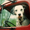
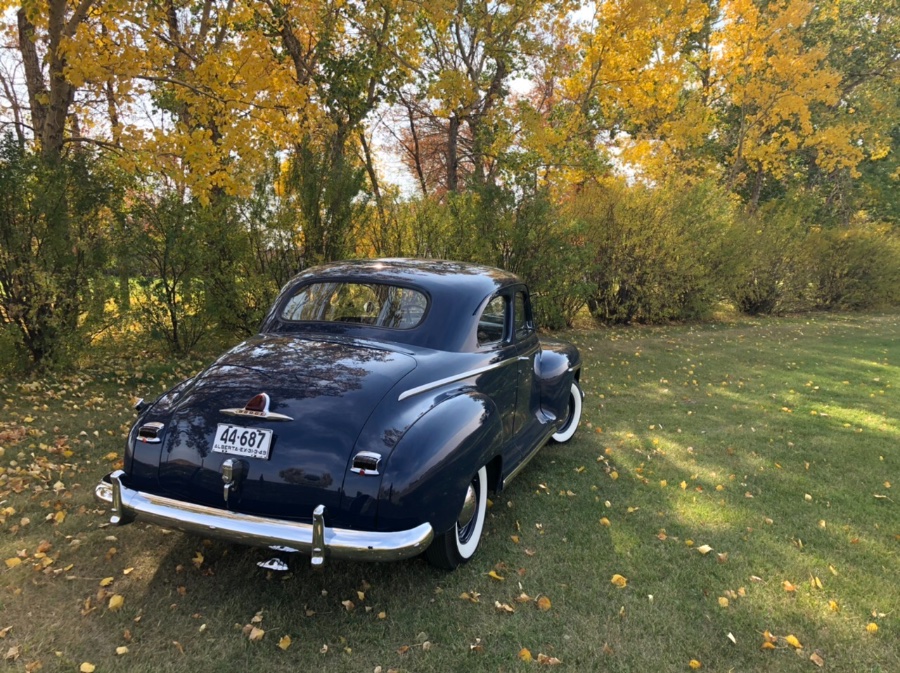
...and that always reminds me of October 2010 when good friend Jerry and I stopped in at Punxsutawney, PA on our way from Edmonton, Canada to Hershey, PA for the big AACA swap meet. The old Mopar connection? We were driving my faithful 1947 D25 Canadian-built Dodge on a 30-state odyssey around the US of A. Pux is all about their most famous resident Phil the Groundhog. The town is littered with groundhog figures and Gobbler's Knob is at a park just outside town. We even caught a glimpse Phil in the town's Groundhog Museum/Public Library. Good times...


 2 points
 -
There is no question the Dodge Brothers MADE the Ford Motor Company. The history is all too clear if you want to take a look at it. Henry Ford was convinced he was the smartest guy in the room and he was as stubborn as hell. A tea totaler he used to break into Edsel's house and smash the contents of his liquor cabinet. The Dodge Brothers both drank a little too much and got into trouble from time to time, so there was that. Mostly they parted ways when Henry refused to pay their dividends. The Dodges sued and won. I've often thought Ford kept the Model T so long because the Dodges weren't around to design the Model A. Henry Ford it seems was not the great visionary or engineer the propaganda makes him out to be. He had a lot of help along the way and buying out his stockholders was a big mistake of his. Having other opinions expressed in an organization keeps things on track. Walter P. Chrysler of all the automotive pioneers had that figured out. He found the best men, then trusted their work and the results speak for themselves. Henry's well known antisemitism brought him an embarrassing moment which he richly deserved. He sued a newspaper for slandering him. That brought on a trial during which he was called as a witness. He was asked very simple questions about American history and was found to be astonishingly ignorant once in the witness box. He couldn't get away, he had to answer the questions as best as he could. The lawyers really brought out his true colors and made him squirm. Finally when it was over the jury found that he had been slandered.....and awarded him $5 in damages. Needless to say he never sued anyone again. The whole experience should have humbled him but it didn't. I try to understand where his personality faults came from. I think he was a guy who was not prepared for his success and it got the better of him. On a visit to the Henry Ford Museum I came upon a truly massive double acting twin cylinder steam engine/generator from the power plant at the Highland park Ford factory. This thing was impressively huge! To look out over it and imagine I was Henry Ford and this was my machine gave one a sense of power. Then I read the information card next to it. This incredible machine was only one of EIGHT in the plant and the one Henry saved. Then I understood his megalomania. Most of the country lived in houses with dirt floors and no indoor plumbing when this generator first ran. It had to give him the impression he was king of the world. If Ford had been run by Walter Chrysler there would have been no General Motors or any other competition for that matter. Ford at one time made more cars than all the other manufacturers combined. Chrysler's management style I believe could have kept that going forever. Just my humble opinion.2 points
-
Brent if you make it down to the Kenai Peninsula give me a shout. Fishing the Kenai river for Kings, (if they have a season this year), is an awesome experience. We also have trophy trout in it. 30" ers aren't uncommon.2 points
-
I have very limited headroom in my shop space so no possibility for a full height lift. I've found a kwik-lift to be a nice compromise between Jack stands and a full lift. I've had one for years. You can typically find them used for $400-$800. https://www.kwik-lift.com2 points
-
You ever pul a thread on your shirt and the whole thing unravels? ?2 points
-
This was the stepping stone that lead to the early hemi engines. There was also a V6 hemi concept drawn up, but I don't believe it was ever manufactured. I also might have the development number wrong.... I have ran across conflicting information that i haven't been able to sort out. For testing purposes they developed all kinds of cool stuff. Such as the engine in the original post, they also had a dual overhead cam version, I found reference to an aluminum OHV head that had a flat face (not a hemi - or even much of if any type of a combustion chamber). That is what companies and and people do - they develop things. Sometimes they make one and done. Sometimes its evolutionary trying out different directions and paths.... and just like Darwin's theory.... only the fit survive. Perhaps that fit is cost, perhaps performance, perhaps weight, whatever it is.... new things get tried and tested and only the best for the task is developed further.2 points
-
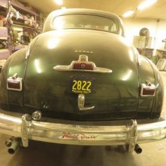
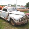
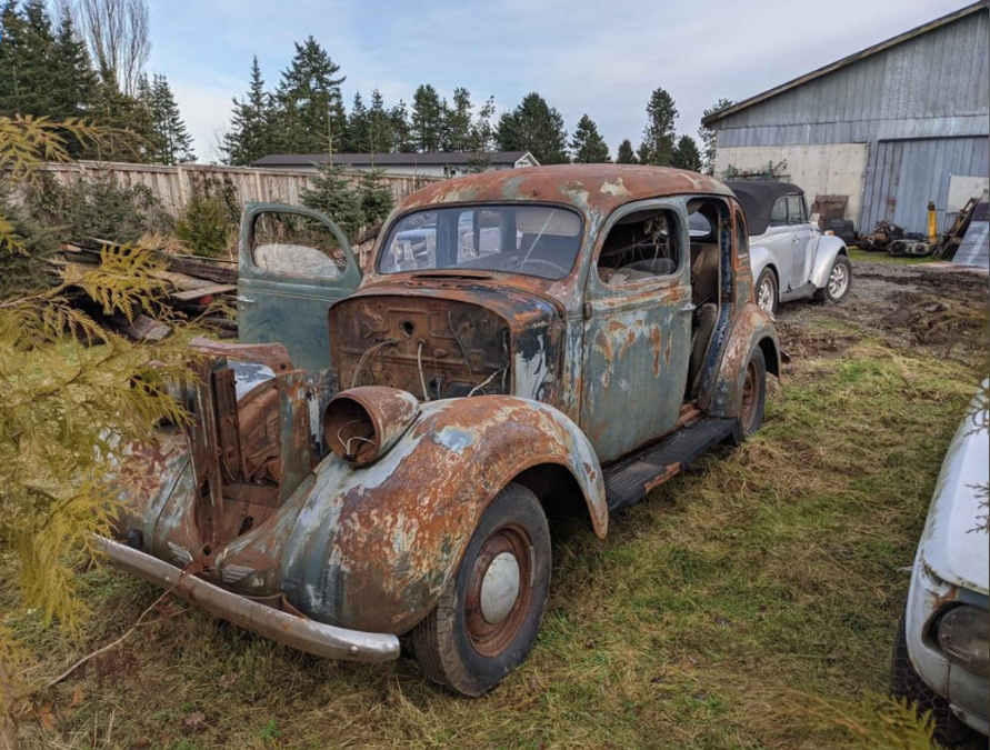
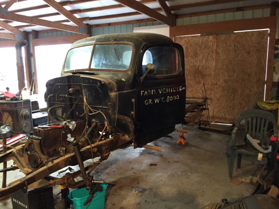
To update a seller who is out of touch with the vintage Mopar hobby? Crazy asking prices because the car is old. It's rotten. It's priced out of the market. It doesn't run. The threat..."When I get it running in the spring, sell price will be much higher!" I bite my tongue and let it go. Sometimes I do want to send the seller a message and say, "friend you are way out to lunch. If you really want to sell that car, (and I ain't looking, nor interested) you really need to be in xx,xxx price range." Here's my latest example. A 1938 Dodge. This one is listed for almost exactly what I paid for my car, that at least fired up and drove ½ way up the trailer ramp before it gave up. Pic as seen rusted in the field with "amazing patina". Asking price $3400 CDN. Pic 2 my car as found aside from the new tires. First day I had it running on the street. Maybe I got lucky when I paid $3500 CDN? I'm not so sure. I keep pouring money money into it. Expecting .25 return per dollar some day. Am I the spoiled brat here because I think that the rusted '37 Dodge with the great patina is worth $500 tops? I could maybe use the diff, steering gear box, glass, etc...Yet I need to go drag it home and have it sit in my yard for months, maybe years as I part it out. Putting in my time and effort also selling parts to keep other old cars on the road. I dunno. Maybe I am jaded? $500 tops...
 1 point
 -
no insult sir, one needs to take constructive wording to learn and i want to learn, i will check the points...1 point
-
it is not the idea of the missing head bolts...I proposed that work around already....yes, I am 100% skeptical on the engine.....it defies too many mechanical principals BASED soled on the pictures shown and the line drawing. I would not say this was not a proposed idea...I just do not think the idea bore fruit of a magnitude that led to a working design much less limited testing production. I believe the head was designed based on the Thunderbolt engine for the intended use on that of flathead but the valve geometry was the fatal flaw. This development however worked better with a cam positioned centerline to the opposed cylinders as compared to the offside flathead 6, thus the success of the hemi V8. I will remain open to any other evidence to support this engine, the valve train however with push rods working offside to a centered position over the cylinder....the angles are just to acute... not here to argue with you but on your statements just a couple posts back you said there was evidence that these hemi head 6's were used in road tests and this was a most likely candidate as it would be a bolt for bolt swap to vehicle in current production...this I would agree with....if this was one of said engines being tested....but still have to wear the D. Thomas cap here...we seems to have lost our entry post numbering system again. I would like to think this engine bore fruit even if it were say nixed by the bean counters....but few bean counters controlled R&D...1 point
-
the blue one in in tekoa WA1 point
-
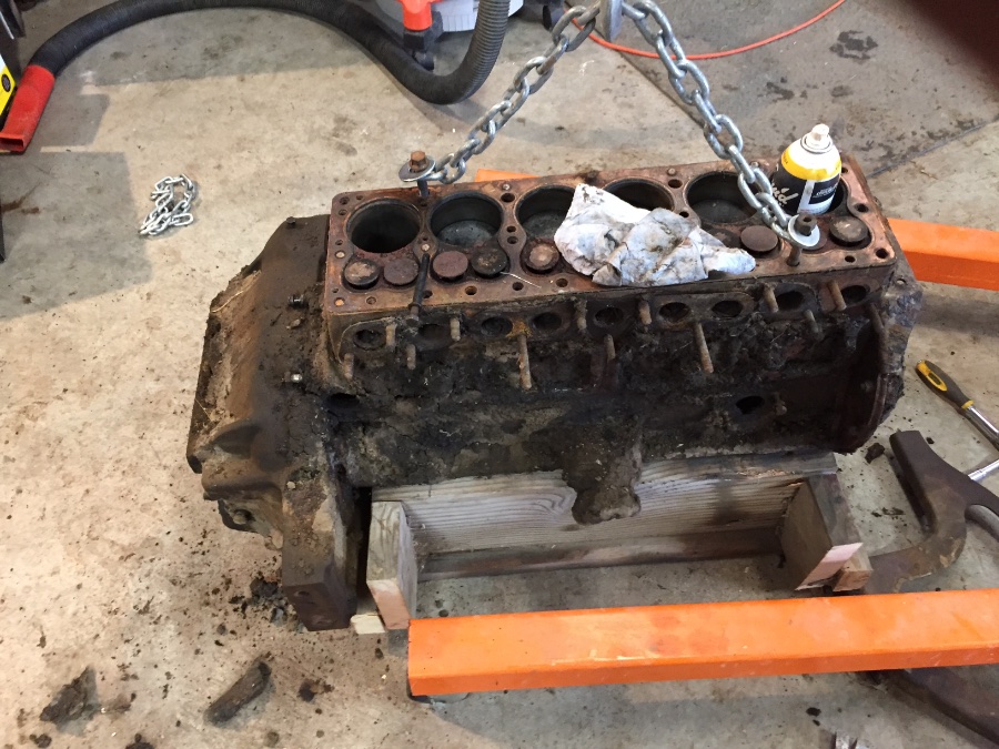
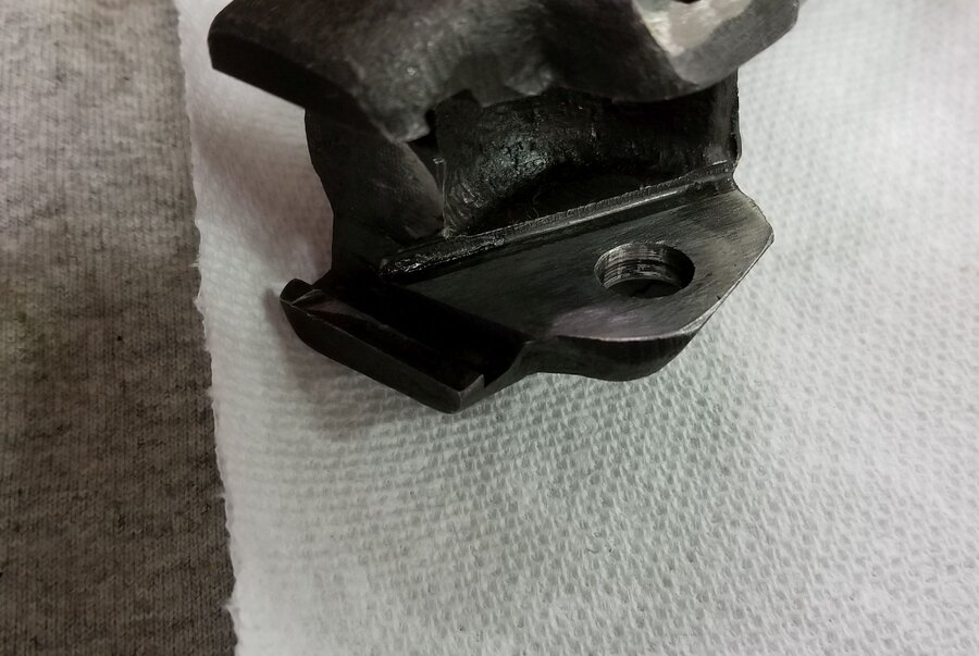
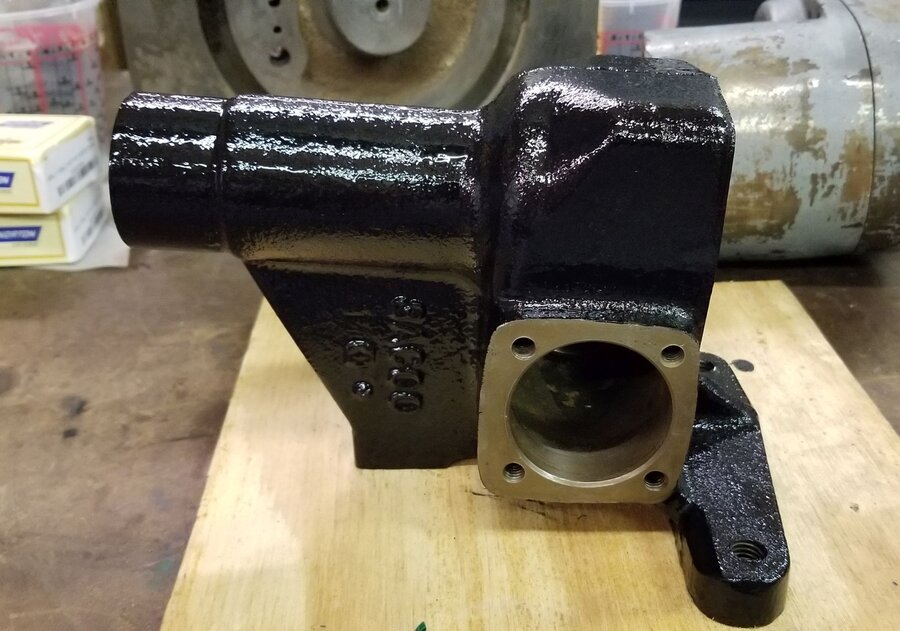
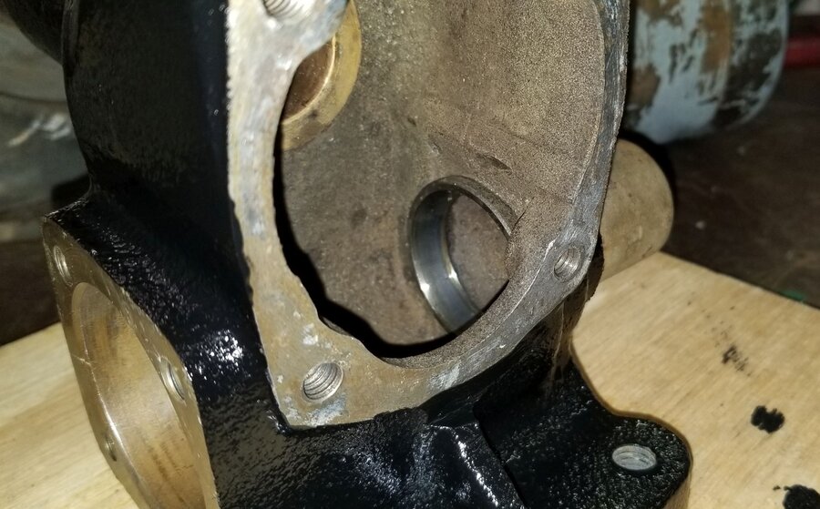
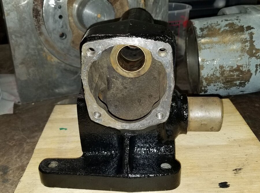
@Eneto-55The temp probe on the right is electric. That 25" engine came out of a '54 Canadian Dodge. 228 ci. That engine resides in my '38 Ply car. That engine is out now, torn down for rebuild. That head has the slight bulge cast into it at the front to accommodate the water passages for the by-pass type water pump. I want to re-use that head. My plan is to drill and tap it for ½" NPT, so I can utilize the stock temperature gauge system in my '38 Ply car. The head on the left is spare head that I have from a 1948 25" Canadian Dodge. 218 CI engine. It is indeed tapped for ½" NPT. However that head does not have the cooling passage for the by-pass water pump. Additionally, neither head does me any good without the gland nut that I need. Oh the joys of swapping major components.1 point
-
This may just be a personal bais of mine,but if the plugs are Champion,throw them at someone you don't like,and replace them with practically any other brand. I mostly use AC ,but that is primarily for convenience. I am not saying they are better than any plug except for Champion. I will hurt anyone that ever puts a Champion plug in any of my cars. I am serious about this. BTW,I want to congradulate you on having the courage to get rid of the Chevy and enter the world of Mopar. Not only that,but you jumped in with both feet by buying a very rare Mopar on top of it. I like hot rods more than restored cars,but cars like your 39 convertible are too rare to modify and I hope you try to keep it reasonably stock. Do what you have to do to make it safe and reliable,and then just enjoy the damn thing.1 point
-
"Wildcat Mopars" and other mopar wrecking yards have been telling for the last 10 years.....over seas markets are driving our prices up. Wildcat sold 5 or 6 E bodied cars to Saudia Arabia, and another E body to South Africa. The guy in Grizzly, Ca told me he hated to sell to locals because he got so much for parts over seas. I'm not getting any younger, I used to get 68 Chargers for nothing in 1985.......last time I looked, a beater with no motor is 25 grand. 48D1 point
-
too much time on your hands Tim?1 point
-
2-2: Into work with the Meadowbrook again today. Here's some frosted over pics before I left at midnight.1 point
-
Depending on the garage door height, they make a drive on lift with casters so you can roll it outside for full height. About the same price as the scissor lift. Pay special attention to the delivery requirements on any lift, most require a forklift or similar for YOU to unload from the delivery truck, or you get a trailer and go to the freight yard and they will put it on your trailer. Then you can use the overkill gantry crane to unload it from the trailer, lol.1 point
-
Maybe a MaxJax would be better...depending on concrete etc... https://www.maxjax.com/?gclid=CjwKCAiAjeSABhAPEiwAqfxURWZKcV0pq2Dz1OPfnEwMaLlRCp2oDHgy78qRz6gti4JzWKD8crzHNBoCKksQAvD_BwE1 point
-
The single blue fuel tank sender wire (1949-52) ends up at the back of the fuel gauge...usually goes up thru the drivers side roof.... down "A" pillar on to gas gauge...look for the blue wire.1 point
-
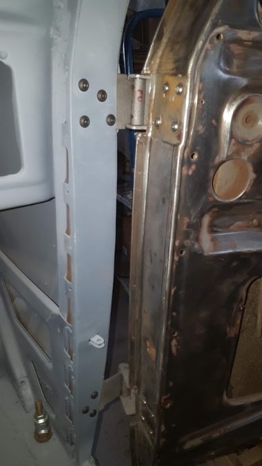
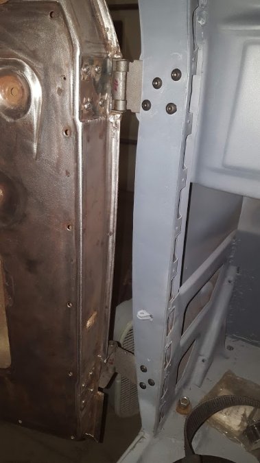
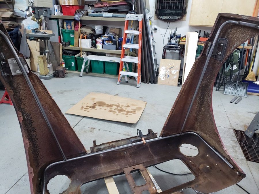
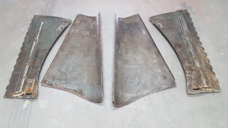
Latest update from Mr. Joe Jarvis: "Set doors on cab with the rebuilt hinges, made sure they fit before we body work them, next step is to seal and body work. Rear fenders are going to need done while bolted on bed. Left rear fender is about half finished. Hoping the motor mounts are done this or next week."

 1 point
 -
body of fuel sender to ground. wire from terminal on sender directly to fuel gauge terminal via the rear tail of your main harness to your fuel level indicator ( 1 terminal I think cause they must have corrected that 2 terminal furd idea by then). Case of instrument in dash should be 0 ohms to ground. Hope this helps and if it don't just ask. Mes Saluts! M1 point
-
That has always been a pet peeve of mine, I look at a motor being electrical and an engine combustion (fuel) I know "TECHICALLY" a motor can be an engine but I don't like it. ?1 point
-
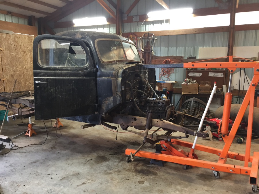
The weather improved some so I was out working in the shop removing my gas pedal linkage. While there I thought I would see if I could loosen the motor mount bolts. Surprisingly enough they came loose. So I thought why not hook up the hoist and see if I can pull them out. Out they came and before I knew it the engine was out. Why are they called motor mounts? Shouldn’t they be called engine mounts?
 1 point
 -
One human factors issue that has bothered me on this forum software for a while: If you are on a mobile device (or other small window as you can demonstrate this on my laptop by reducing the window size) is that if you want to mark everything as read the button on the pull down from the “hamburger menu” is adjacent to the sign out button. It is too easy to hit the sign out when you wanted to hit the mark all as read. And this is compounded by the fact that sign out is immediate with no confirmation. If/when you get a chance to suggest improvements to the vendor, it would be nice if a change was made. At the least put a confirmation dialog box on signing out. Or just move the two buttons away from one another.1 point
-
Just for Entertainment I'd like to mention that putting OHV heads on side valve engines started with one of the first engines with a removable head, the Model T Ford. I am not ashamed to mention Ford here as with the exception of wheels and body the car was made by the Dodge Brothers until 1914. A removable head and cylinders cast "enblock" were a huge advancement. The Ford/Dodge Brothers Model N R & S had cylinders cast in pairs with no head and attached to a separate crankcase. Since the Dodge Brothers made most of the car (and financed Ford) I figure they had more than a little input as to design. After all they had lots of skin in the game. Back to the Model T In 1916 Robert M. Roof created the first Over Head Valve conversion for the Ford. It had 16 valves ala Peugeot. The exhaust came out of ports in the head while the intakes were in the block using all 6 ports. It wasn't very successful as the valve guides leaked as the engine wore and it won't idle properly. When they ran they ran with considerable power. There were two sets of push rods. One set of 8 running in the block valve guides and another set of 8 running in guides in the head acting on the rockers. This was needed because of the intake ports being in the block running up to ports in the head and as you might imagine the inability to line everything up. This head started a whole industry of "Speed Merchants" including the Chevrolet Brothers. Back to the Chrysler I doubt if the Engine Design Department built the engine with a thought to production. The tappet bores were put on an angle to get the push rods to the rockers. That would have been a big change for production tooling. The angle was about what the V8 had so the heads would be a good proof of concept. The HEMI 6 was nice but not practical as it could not be enlarged to the sizes envisioned for the future and straight 8s were out of fashion.1 point
-
Check out max jax which are made in California. I had a friend in CO who was crushed by a car and have been somewhat paranoid when getting under a vehicle ever since. ALWAYS try to rock the car which has been lifted before getting under. If there is any lateral motion, rethink your lifting method and do not climb underneath! The guy in the video even mentioned that his method was sketchy with the 2x4 stands, so I would believe him! With the price of lumber these days it would probably be more economical to buy approved safety equipment MADE IN THE USA. 25 years on the FD has taught me that overkill is better than getting killed! Y'all keep safe M1 point
-
Years ago, when I was restoring my ‘48 Dodge D25 club coupe I needed to replace a back window which had been shot out. Even then it was a hard piece to find as it was larger than the sedan rear window and unlike the rest of the glass it was curved. I finally came across a club coupe with only one piece of glass in it......the rear window. Found the owner and he said give me $20 and you can take whatever you want off the car. I took the rear window with good rubber moulding, both doors, trunk, hood, and a few other things. Sometimes you get deals but that was a long time ago. Still got that rear window in my coupe. Edit......... Ha ha, found a picture of my coupe when I first got it and had covered the missing rear window with a garbage bag to keep out the worst of the weather.
 1 point
 -
Or you could just build a monster gantry crane and lift the car up to put the blocks under it. Not like I know anyone that built a monster gantry crane1 point
-
In the aviation community we often use stainless steel braided teflon hoses for fuel and oil. Rubber hoses have a recommended service life limit, usually 5-7 years. The teflon hoses have no service limit. If someone wanted to deal with AN fittings and adapters the teflon hoses should last longer than any of us.1 point
-
from day one of my messing with any engine, the use of Permatex has always been the go-to in all the shops I have ever been associated with. The best seal regardless of your favorite snake oil starts with the mating surfaces cleaned very well and assembled free of coolant weep.1 point
-
I hear you. I agree. But I am also content to let the seller sit on his gold mine til is rots away altogether.1 point
-
Remove the 4 bolts that go horizontally between bell housing and frame mounts. It will lift right out.1 point
-
Only the cab is still on the frame with floor boards removed. It has a “floating power” front motor mount. It should pull out easily if I remove the 4 bolts from the motor mount. If I can remove the 2 motor mount bolts I will still have trouble with the narrowing front frame. If I have enough room to turn it I might get it over the frame. Repair manual just says remove mounting bolts.
 1 point
 -
more shoot pics!


 1 point
 -
Using the right rubber mounts is important. I know they are expensive but in the end it will give you peace of mind using the right ones, especially when the car is apart and you are already down to the chassis. You've gone that far so might as well do it right. The old expression "gotta pay to play" comes to mind.1 point
-
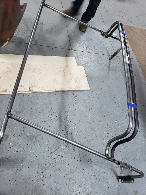
progress from this weekend.


 1 point
 -
Back from the store. ½ pipe reduced to ⅜. Bingo. The 218 head shall be used. Thanks folks. Always a pleasure doin’ business here.
 1 point
 -
I probably should post an update to this thread. The gearbox rebuild is complete and seems to be a quality kit. There is virtually no play in the steering box now and with the new parts in the rest of the steering system it should drive like a new truck. The only thing left is to actually do a test drive. Once that happens I'll post one last time with an update. Brad1 point
-
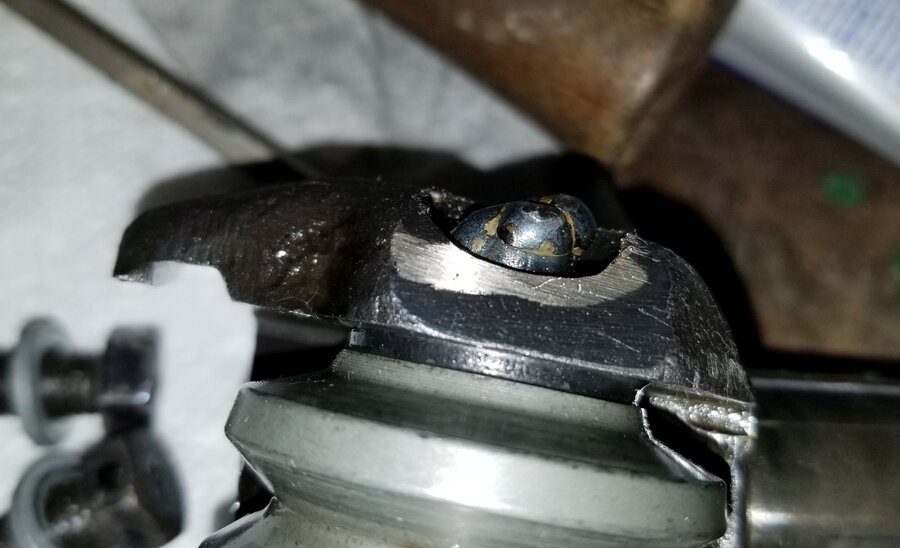
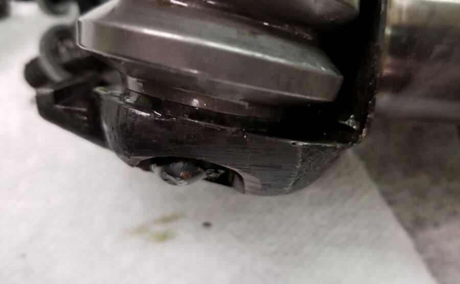
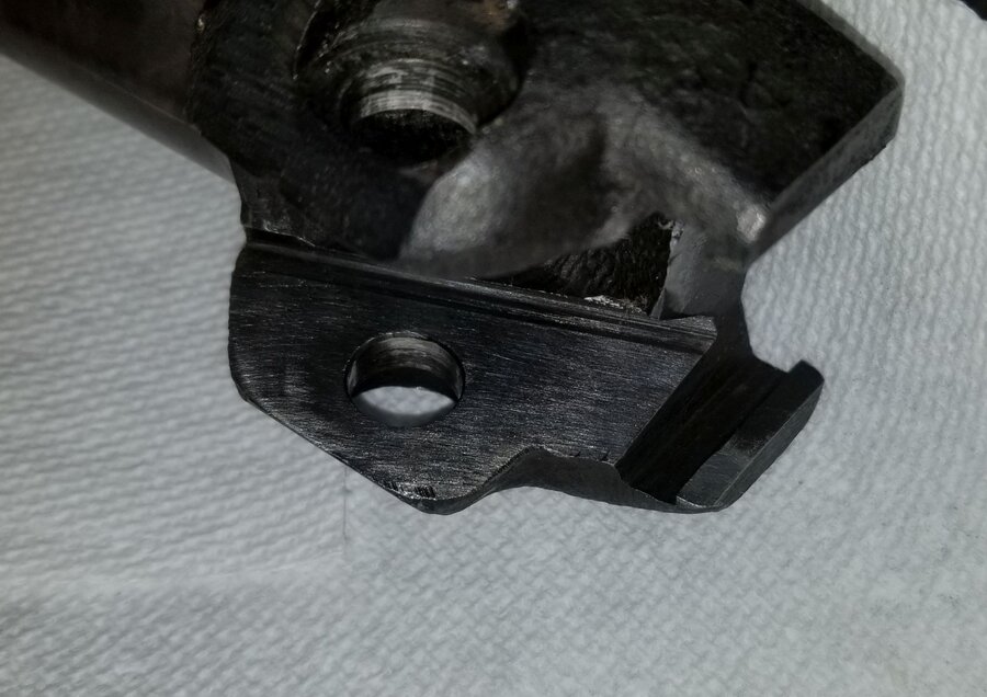
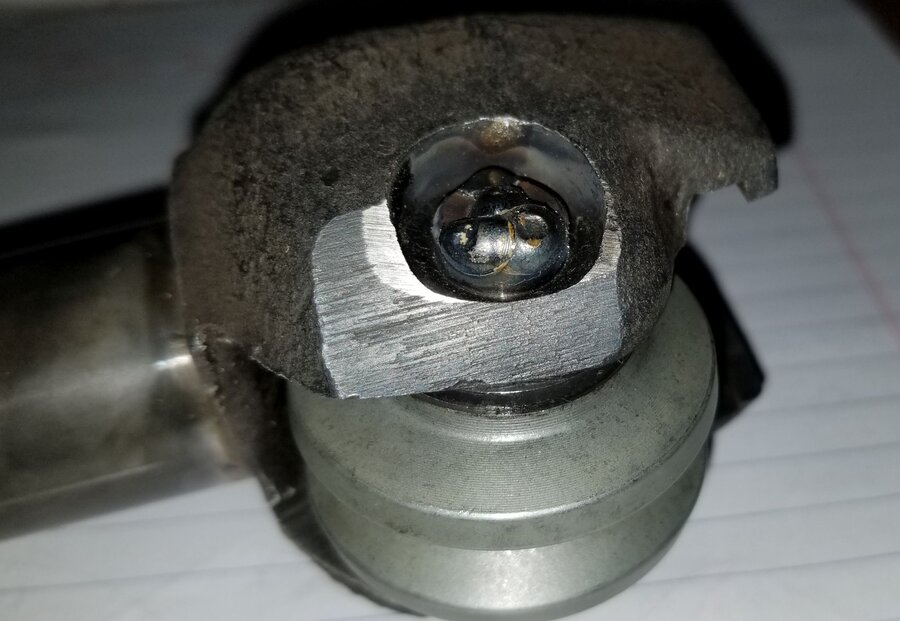
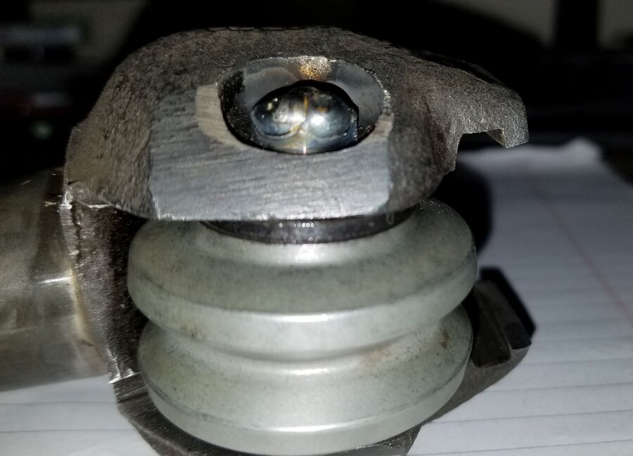
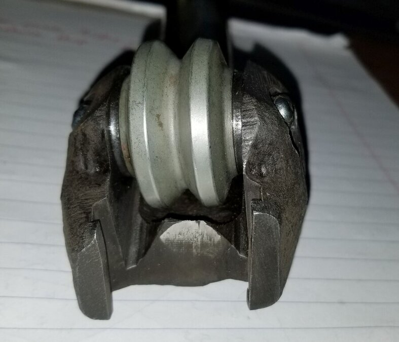
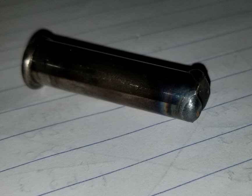
Ok, the steering gearbox is assembled. The final product feels really good. I did however make mistake #3 when I welded the ends of the pin the second time around. I didn't find out about the problem until I had the sector shaft in place and found that I couldn't rotate it through the full range and the more I tried the more the sector wanted to bind in the housing. It took me a bunch of times tapping the sector arm out of the housing, recentering it and trying again. Finally on one of the attempts I noticed that it seemed to be in the same spot (duh!) so I pulled the sector back out again and looked closer. It turns out when I welded the ends of the pin I built the weld up to high and the end of the pin was catching on the edge of the casting inside. I guess there is a reason for the curved grinding that was done on the sides of the sector arm. Pictures of the pin before grinding: Pictures of the pin after grinding: The fix was to tap the pin all the way to one side, grind down the top of the weld bead, tap the pin to the opposite side and grind the bead on that side. I managed to grind enough so that if the pin was maxed out to one side it wouldn't bind. After solving that problem the rest of the assembly went really smooth. Here's a couple of pictures installing the worm: The steering shaft can rotate approximately 4-1/4 turns lock to lock. I made a mark at the 2-1/8 point and I can definitely tell as I'm adjusting the sector arm in and out where the high point of the worm is. Right now I have it set to where I think should be but I'm not sure just how much drag should be felt when the steering wheel is centered. More research is needed. So the lesson learned this time was to make sure the ends of the pin are ground down to allow for clearance inside the casting. I can't imagine what would have happened if I was driving and the pin decided to shift far enough to contact the casting. The outcome would probably not be good. I still need to put the dust seal in place, put the outer tube in place and add the cornhead grease. I'm going to wait on the grease until the whole assembly is mounted in the truck. Brad


 1 point
 -
Had to take a couple of steps back and fix a problem I neglected to resolve prior to welding the pin in place. The issue I noticed after I originally pressed the pin in place (prior to welding) was a "slight" catch of the sector wheel when spinning it. The catch really didn't seem all that bad, you could spin the wheel for multiple revolutions and then once in a while you'd feel a slight catch and have to push past it. My thought at the time was it would wear in during use and not be a problem. Wrong, this was mistake number 2 ? I'll get to mistake number 1 in a minute. After doing a trial fit of the steering gearbox and rotating the steering column shaft you could feel the catch. As I tried to adjust the sector shaft closer to correct tolerance the catch got worse. It was at that point I figured I better fix the problem now. It took me about 20 minutes with a dremel and a pin point cutter to grind the weld off one end of the pin. Not as bad as I thought it would be although I'd prefer not to do it again! Now that I had it apart I needed to determine what the problem was. The first thing I did was to measure the thickness of each spacer washer. They mic'd out at .0795" each. The wheel mic'd at .9765" for a total width of 1.1355". Next I measured the overall width of the old wheel and spacer washers, they mic'd out at 1.1345", so there was a grand total of .001" difference between the two sets with the new set being wider. Back when I gave the spacer washers and roller to the machinist I included the sector shaft as well so he could fit them in place. I did not include the press pin figuring it wouldn't be needed. That was mistake number 1. When I picked up the parts he mentioned that the walls inside the sector arm where the roller goes weren't quite parallel and and he did some light filling to alleviate some of that, enough that the spacers and roller fit smoothly. The shaft itself measures .442" in diameter. For test fitting in his shop I believe he probably used a 7/16" or .4375" shaft. After testing with a 7/16" shaft myself, the .001" extra in width was not noticeable at all. So...... I spent about an hour filling the opening in the sector arm to bring the walls back to parallel. I used a telescoping mic to check fit by setting it on the widest point and filing both sides until the mic would fit where the spacer washers were located. I won't say the walls are perfectly parallel but the roller now fits properly and rotates very smoothly. I've rewelded the pin in place and am now ready to start assembling the gearbox. Keep in mind, none of the above was a fault of the supplied kit from CHS. It was all because I didn't think things through during the assembly process. Live and learn. Evan, hopefully you'll learn from my mistake and make 100% sure the wheel spins smoothly prior to welding the tips of the pin Brad
 1 point
 -
Got the painting done this afternoon. I'll let it dry for a few days and then start assembling sometime this week or next weekend. I think tomorrow I'll clean and paint the outer steering column so it's ready to go. The roller bearing shell I was referring to earlier can be seen in the picture below.
 1 point
 -
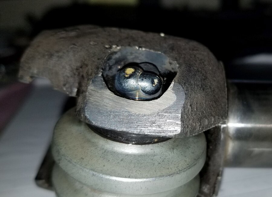
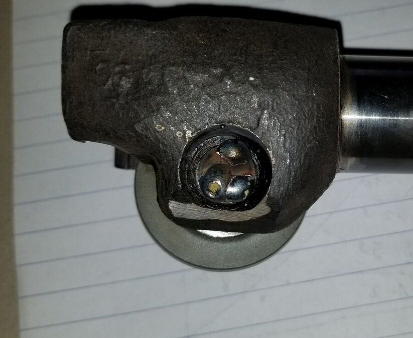
Yesterday morning I came to realize I was I trying to over analyze things and I was making this task harder than it needed to be. Unfortunately over analyzing things seems to be something I'm really good at So, putting aside all thoughts of screwing things up I clamped the old pin in the vice and powered up my mig welder. I set the power level for 3/16" metal and applied a few test beads to the top of pin. I was satisfied with the results of the beads on the original pin so throwing caution to the wind I proceeded with welding beads on the new pin. Before I installed the new pin and roller I took the roller bearings out and greased them with some wheel bearing grease. Below you can see the welding results on the new pin. The steering gear housing is currently soaking in solvent and once it's clean I'll do an initial assembly to see how things look. Brad
 1 point
 -
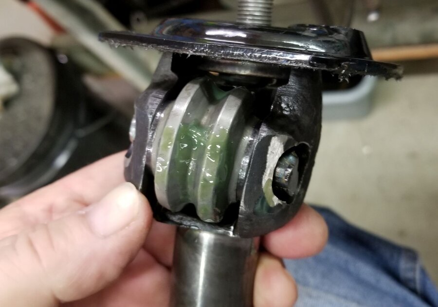
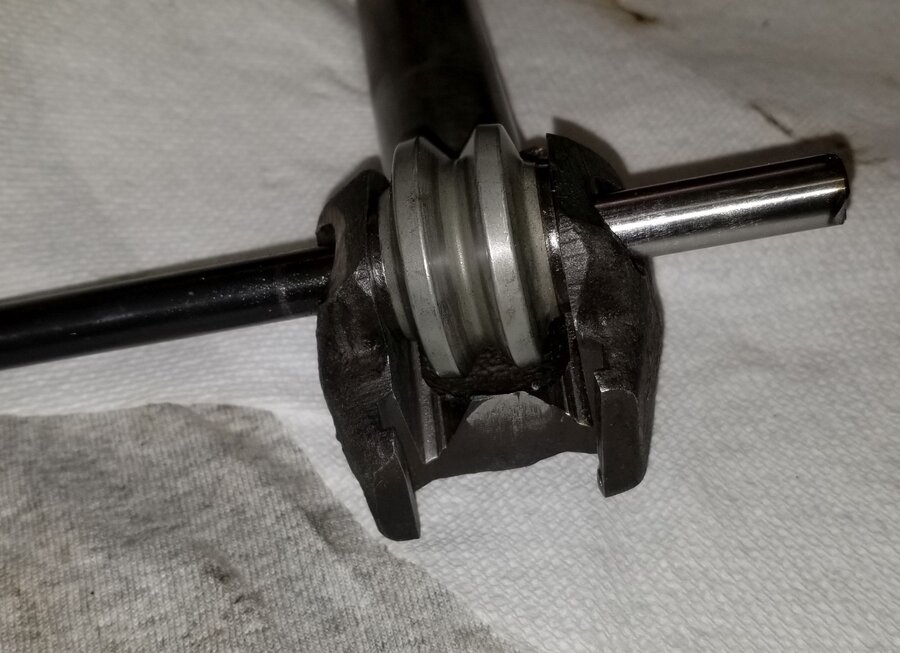
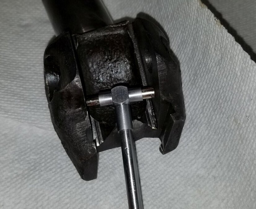
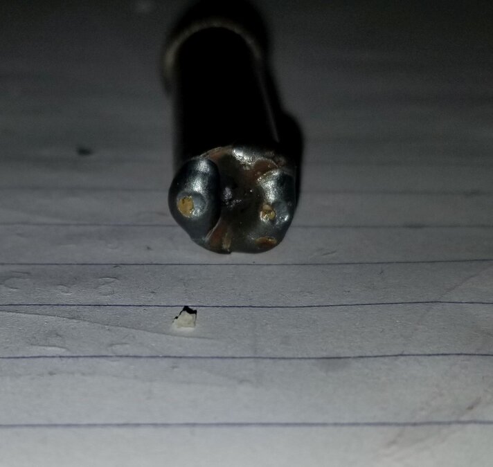
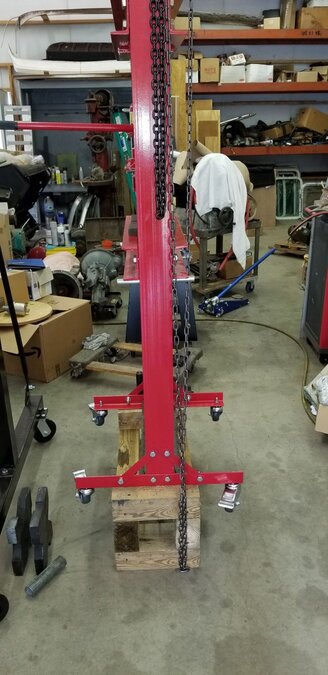
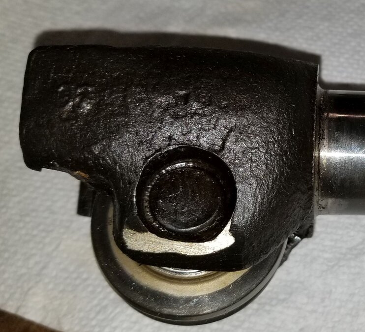
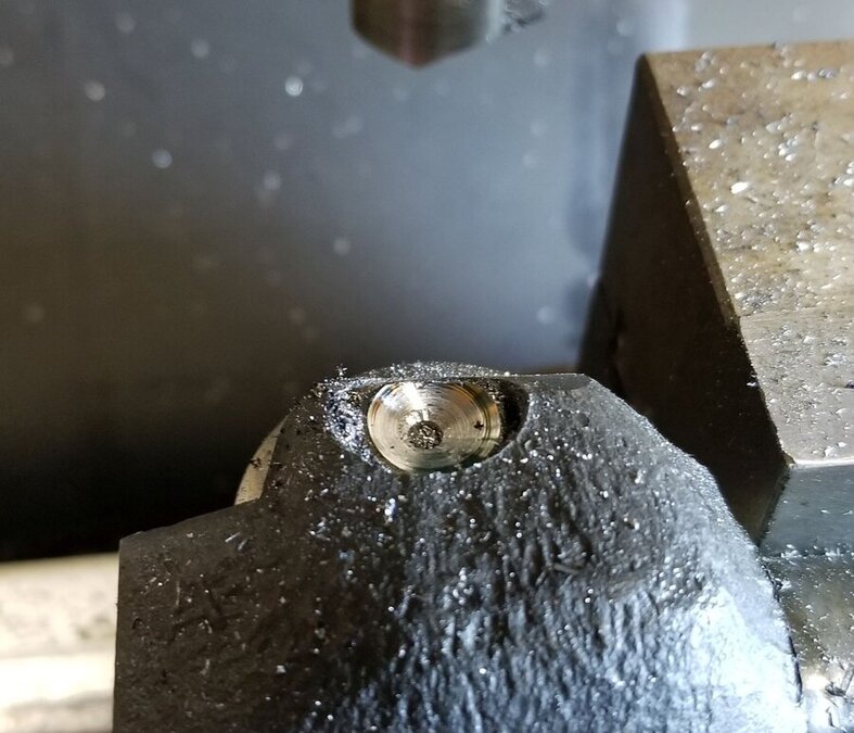
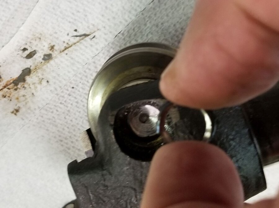
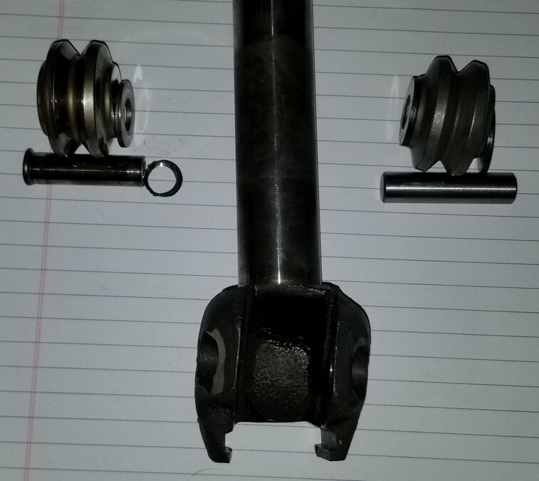
Last night I machined a push pin on the lathe so I could press the worm gear off the shaft. I'm happy to report the job went well. I lifted my hydraulic press with the gantry crane and set it on a wood frame made from 4x6s and 4x4s that I had made previously for a different job. The worm gear removal went well, it didn't take the full 20 tons but it definitely let go with a bang and moved about 1/8". After that it didn't take much effort to press it out the rest of the way. Next I tackled the sector shaft roller replacement. The pin that the roller rides on is basically riveted in place on both ends. I'm not sure how much tonnage it takes to rivet a 1/2" diameter hardened pin but I'm sure it's a bunch. Removing the old pin was a challenge. There is no part of the sector shaft that is flat, square, parallel or perpendicular. I ended up clamping it in my milling machine vice and with a center drill in the quill I did my best to eyeball the center of the pin. At the same time I had to level the top of the pin so it was parallel with the table. This was not the easiest thing to do but I actually succeeded surprisingly well! I was able to start a hole in the center of the pin with the center drill After that I tried a HSS endmill and found out rather quickly just how hard the pin was. My second attempt was with a 1/2" carbide drill bit that I've had kicking around my tool box for over 30 years. I bought it for one job and never used it again until today. I believe it will need to be sharpened before I can use it again. But , it did its job. I almost hit the center of the pin dead nuts. You can tell by the metal ring that snapped off when I started pressing the out the pin. I doubt that I could get that lucky again if I tried. On the left is the original roller, pin and shims. On the right are the replacement parts. The kit states that the thickness of the replacement parts is slightly larger to account for wear and warns that the roller needs to be centered in the housing to work properly. Herein lies the next problem. My original roller and shims measured 1.1345" in overall width. The replacement roller and shims measure 1.152". The new parts are .0175" wider than the original. The fit of the original was nice and snug in the pocket and spun smoothly. The new parts aren't close to fitting. I measured the individual width of the rollers and the original was .969" and the new one is .977" which is .008" wider. This means I can't swap shims to makes things fit. The only option I can come up with is to take the new roller and shims to the machinist down the street and have him surface grind the two new shims to remove .0087" from each shim. Once all that is done I'm left with one last problem which is how to fix the new pin in place. The kit instructions suggest that if I don't have a riveting press handy to rivet the pin in place I can weld each end to the sector housing. I have a feeling that's the approach I'm going to have to take. I'll update things as I make progress. Oh yeah, one more minor problem! With my current hydraulic press configuration I don't know how I can press the worm onto the steering shaft. The bottom of the shaft needs to be press against a solid surface that is part of the press. Looks like I'm going to have to do some jury rigging to my press to get the job done. Needless to say this job is not a simple take the old parts off and put the new parts on type of job! Brad
 1 point
 -
Gramps1951 - yes, I came across bkahler's write-up and have contacted that company. They confirmed part kit referenced is still available.1 point
-
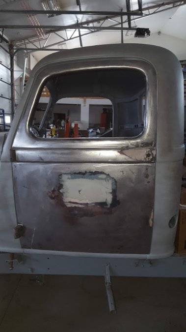
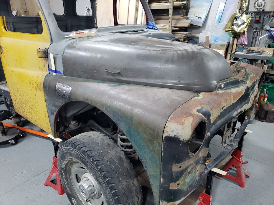
Checking the fit of the hood.


 1 point
 -
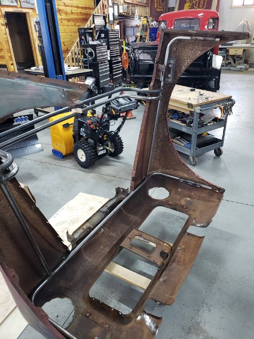
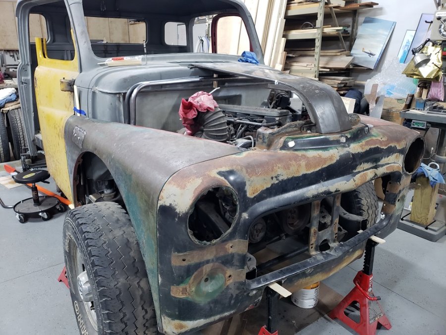
Firewall and floorboards installed.


 1 point
 -
No HEI wires won't work. HEI uses the same type of connection on bith ends of the wire as we do on the spark plug end. You need a different connector on the distributor end than the HEI style wires use. This is what I did when I redid my plug wires. http://www.yourolddad.com/plug-wires1 point
-
Timing will cause one to run hotter also. Not just initial timing but mechanical and vaccum advance play a part. My diaphragm in my vaccum can was broken and fixing the vacuum advance, checking mechanical timing and vacuum advance timing to know where everything was helped my car run cooler.1 point
-
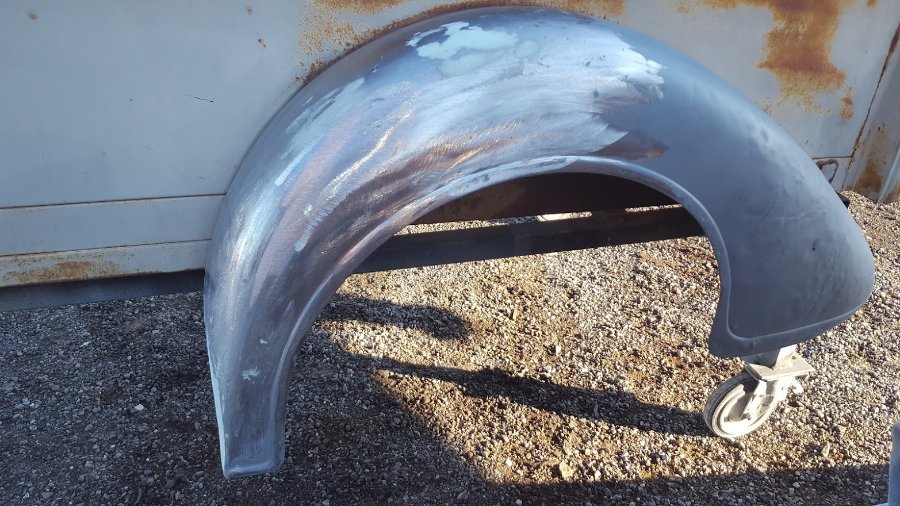
From Joe Jarvis: "We wire wheel these, then have it LIGHTLY sandblasted, too many problems in the past with warping on hoods so this cuts down on the heat from the sandblasting and allows it to get to the small area's we cannot get to with sand paper or wire wheel."

 1 point