

3046moparcoupe
-
Posts
262 -
Joined
-
Last visited
-
Days Won
1
Content Type
Links Directory
Profiles
Articles
Forums
Downloads
Store
Gallery
Blogs
Events
Classifieds
Everything posted by 3046moparcoupe
-
had a couple of holes in my rocker moldings as well, (places where they just took a screw and drilled it through the moulding and into the car),....took it to a place here in the dfw area called "concourse moulding and trim repair " took them about 15 minutes to weld up two holes,.....I think they charged me around $20.00, this was just last year in 2016, if I remember correctly they told me they used a combination alloy wire that has both stainless and steel in it,...then I took it and filed the spot weld down with a file, then kept polishing the area until I got to a 2000 grit....basically the places go away. Steve
-
Trying to contact forum member K_Jordan / can U help
3046moparcoupe replied to 3046moparcoupe's topic in P15-D24 Forum
bump -
Can't tell ya how many times I've come in frustrated after working all day, and logged on to chat to have either Plymouthy Adams, or Young Ed, or DodgeB4Ya, and others,.....share with me exactly what I needed to know, or was missing. Chat will certainly be missed, big time, by this forum member....Thank you Forum and its members for all your patience and help.
-
Back in march I created a post in the wanted section regarding my need to obtain a set of 10" rear wheel drums/hubs for our P15. I just noticed this past Tuesday that a K_Jordan located in Winston Salem NC had replied back a few weeks ago - stating that he has a set that he's run for the last 1 1/2 years - ( until he recently did a complete rear diff change out) , and he was offering to send some pics of the hubs/drums. I've sent him a reply back message - but the forum notes say he hasn't logged back onto the forum - so he hasn't seen my reply. if anyone can help me get in touch with forum member K_Jordan is would be greatly appreciated. Thank you all. Steve Gentry #817-590-9716
-
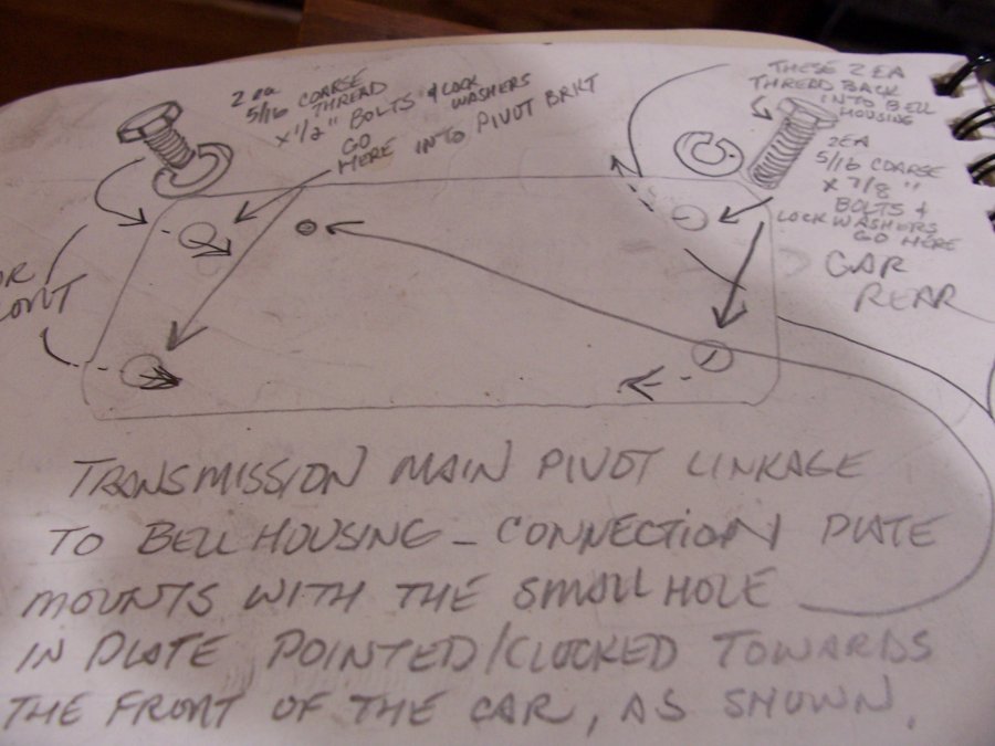
thxs for looking DB4, and yes 1/8" hole sounds correct....after I posted - I also found this drwg I'd made (attached) which shows the bracket (with the little hole) and per the drwg when I removed the brkt the hole was visible, and it was clocked towards the front of the car....sounds like maybe the hole isn't used, I'll go back with it the same way, located towards the front of the car. S.
-
DB4, thanks again,....I drew all this out about a year ago, long enough that I'd forgotten what all I drew,...after you were good enough to reply back, I was digging deeper into my drawings and low and behold, look what I found. (attached drwg) Crap - pretty sad when ya can't even find your own notes, huh ? !! hangin' in there - like a hair in a biscuit appreciate you taking the time to reply back. Steve

-
You don't possible know about the little spring hole also by chance ?
-
DB4, Thank you...that was embarrassingly quick,....:) I sure appreciate it.. S.
-
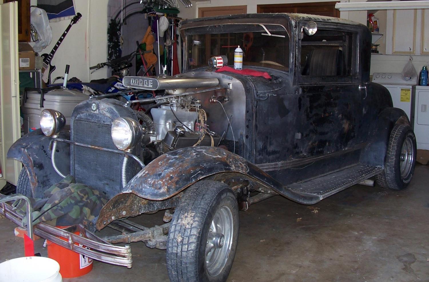
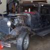
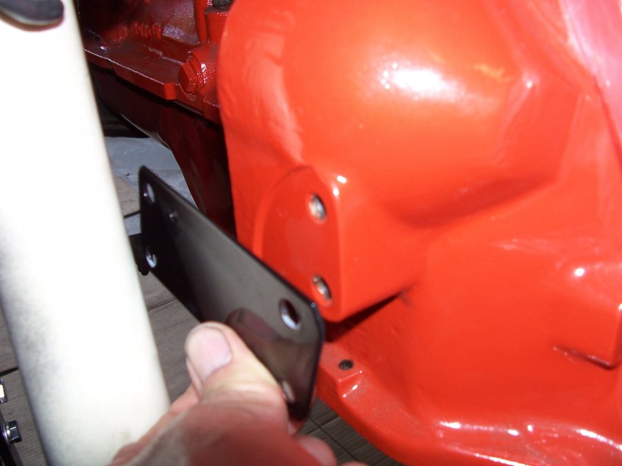
Reaching out for a little help if possible. Attached pics are of the bell housing on our 46 model flat six 218, inside the cab, drivers side, immediately next to/below the starter bolt up location. Pic#1: The rectangular shaped black piece with a hole at each corner is called the "Spring 6-58-5" ..it's the bracket that the Torque shaft attaches to on the engine side. I drew all this out in detail when I removed it - however in putting this all back together there are two things that have me uncertain...guess my details weren't detailed enough Pic#2-3: The Spring Bracket is flat, so when it's bolted down firm with the 2ea 5/16 bolts (as shown in pic#3 where they are just finger tightened down) against the bell housing, that 1/8" or so lip/edge on the bell housing is going to either bend the Spring Bracket or just curve it outward,..I guess ?? I didn't want to try it yet to just find out yet in my mind, I know it came off here and I feel sure there wasn't anything behind it, like a spacer, etc...course maybe there should have been ?? dont' know. Pic #4: This is the only drawing I've found, looking down from above on the torque shaft....this diagram is from the 46 P15 parts list manual. with associated parts breakdown as follows: Spring 6-58-5, Clutch Torque Shaft Clutch Housing Pivot Bracket, pp# 871993 1ea. Attaching Standard Parts are: 2ea 1" 5/16 bolts, 2ea 2" 5/16 bolts, and 4ea 5/16 washers. (So it doesn't say or show anything else as being required, like a spacer, etc...also in the diagram in pic#4 if the spring bracket is supposed to be bolted down, directly to the bell housing, and up against that 1/8" ridge/lip as I have it in pic#3, then they chose not to show that in the diagram as it just depicts the bracket being bolted up against a flat un-labeled surface.) Anyone out there able to take a look at their P15 and let me know how this one bracket should correctly bolt up...if this is correct,...or if I'm missing something here...it would be greatly appreciated. Of course I'm just taking a wild swag here, but I'm wondering if possible the reason it's called a "Spring" in the parts manual, is that when bolted in, across that lip/edge, it might give the bracket the ability to serve as a spring, sorta like a diving board effect,...?? but I'm just throwing that out there in effort of trying to make sense of this bolting up the way I have it as shown in pic #2. Also, the Spring bracket plate has a little hole in it separate from the 4ea mounting holes located at the corners. It's over on one end of the brkt. Seems like that would have to be where a spring connects. I know when I took this all apart, a previous individual had attached a spring around one of the torque shaft pins...I documented where it was attached, but it was obvious it wasn't correct.....I'm thinking the correct spring probably attached and anchored at this tiny hole..but obviously guessing...All that said - since the hole wasn't being used before (I don't even think it could be seen from years of grease, etc until I'd removed it and started cleaning it up),.I don't know at this point if the end of the brkt where the hole is located should be placed towards the front or the rear of the car..and exactly what it's for... I greatly appreciate any and all replys. Thanks again for all the help. Steve


-
p15 oem brake pedal linkage assembly parts location
3046moparcoupe replied to 3046moparcoupe's topic in P15-D24 Forum
Thanks Don, that really helped...on pg 2 of your photobucket brake album link above, the 15th photo, shows your setup in the more stock configuration, which shows the spring clip resting on the right hand side of the pedal shaft (just like the enlarged photo I attached above with the red and green arrows), again this method also explains a use for the curved lip/ridge found on the edge of the pedal shaft, which acts as a stopping post for the spring clip. Chazz47, if you click on the attachment Don provided and go to pg-2 pic#15, you'll see what I'm trying to describe. In respect to these two photos, you might want to look at moving your spring clip to the other side, especially if the base of your pedal shaft has the curved ridge in place that encircles about 1/2 way around the casting. Don, I was looking at some pics of your blue car, you had the vintique wheels on, were those 14 or 15' wheels ? Thank you. Steve http://smg.photobucket.com/user/DonCoatney/media/Brakes/eyelet.jpg.html?sort=3&o=38 -
p15 oem brake pedal linkage assembly parts location
3046moparcoupe replied to 3046moparcoupe's topic in P15-D24 Forum
trying to get this image to enlarge. test run #1 yeah it appears to have worked. Chazz47 take a look at this picture, see how the spring clip (oval part wit the little hole in it) is located on the opposite side of the brake pedal shaft. Does your brake pedal shaft, where the nut and cotter pin are located at, have a lip or ridge that stick out about half way around the casting where the bolt goes through the shaft ? If so, I think that ridge is supposed to hold the spring clip in place. maybe this will help you as well. Steve -
p15 oem brake pedal linkage assembly parts location
3046moparcoupe replied to 3046moparcoupe's topic in P15-D24 Forum
Thxs Chazz for sending the pic my wayt. I wish I could say it helps to confirm, but unfortunately it adds to the mystery..:) best as I can tell, on yours - the spring clip is sandwiched in between the actuator rod and the pedal shaft base itself, which would mean that we now have an example of it being installed 3 different ways..over the years I guess many things can happen, and obviously I'm not the only one experiencing a bit of difficulty in determining which assembly order is correct. More importantly though - you went the extra to try and help a forum member . I appreciate It and your time. if and when I find out for sure I'll let folks know. Not trying to make a mountain out of a molehill. I expect it would work to some degree assembled any one of the 3ea ways, but it sure would be nice to get it put together correctly. also - sorry folks, I didn't realize that when I Steve downloaded the picture in the last post, it would remain so small it is basically useless, the original phot was large enough to tell whats going on. I'll see if I can get the pic enlarged. Steve -
p15 oem brake pedal linkage assembly parts location
3046moparcoupe replied to 3046moparcoupe's topic in P15-D24 Forum
I found this picture here on the forum, from a post back a few years. Brake pedal assy seems to be identical to mine, and the pic shows the parts going together with the spring clip (oval piece with hole in it for spring to attach to) located on the opposite side of the pedal shaft base, than where I had thought it went. Also, (unless I'm not seeing the forest for the trees here .. that would mean that the parts diagram in the pic I posted on the initial post here, is not correct. Sorta make sense as to why that oval shaped lip is found on the lower half of the pedal shaft base, as I'm thinking the spring clip needs to rest against that ridge/lip to do it's job with the return spring. see attached pic thxs Steve
-
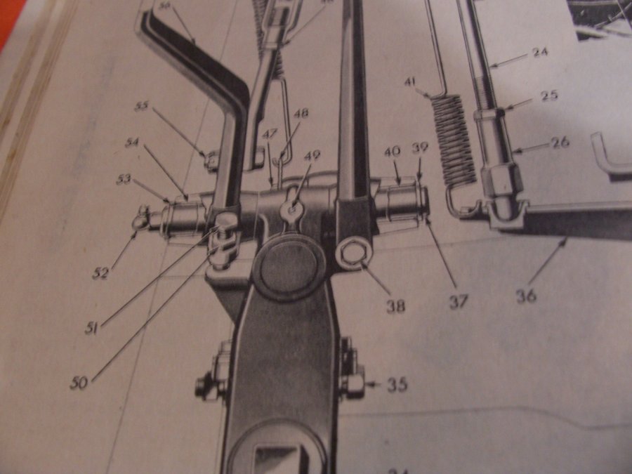
Not sure if all the linkage parts connection the brake pedal to the master cylinder are assembled correctly the way I have them here. In looking at the diagram found on pg:36 of the P15 Passenger car parts list manual, (pic #2 attached) it shows part #47 (pin) which is the connecting bolt and it appears to be coming in from the left side of the pedal (as I have it positioned here in pics 1 and 3, then the brake pedal return spring clip appears to go on to the pin next between the head of the pin bolt and the actuator rod eye bolt, then through the pedal shaft itself, (that's all that's shown on the diagram), ..next I have a washer then the castle nut..( cotter pin required but not shown ). I took this apart 4-5 months ago, and it was so basic at the time, I thought no need for a pic or sketch,....WRONG !! of course now I can't remember squat....( so before finding the diagram I was trying to insert the bolt from the opposite direction).. So in reference to the diagram shown in pic #2. the parts look to go together as I have them laid out in pic #3.... I do know that when I took this apart there was only a single washer, and now I'm guessing where it was. No washers are shown on the diagram (but they also don't show the castle nut either, course in the picture those parts would be hid behind the pedal shaft itself..... pg:32 of the P15 parts list manual does show the following parts in the master cylinder brake push rod section: 1ea push rod, 1 ea push rod end, 1ea push rod pin/bolt, 1ea hex nut, 1ea WASHER, and 1ea cotter pin.....so it sounds like a single washer is correct for this...and having it located underneath the nut would make the most sense to me. If anyone out there know's for sure or can possible take a look for me to confirm if this layout is correct...It would be most appreciated... Thank you. Steve


-
DB4ya, I forgot to say - I do believe you got the best profile pic I've seen here on the forum. That's a classic for sure !! S.
-
Thanks for the time taken to reply back....I should be shorter in verbage with my questions,....more to the point, should the fit here at the pinion yoke have some interference fit / or not ? I chatted with a fella here on the forum yesterday whom I have spoken with before and he stated that typically he had to use a puller to remove the pinion yoke, that in combination with the manual also showing the Miller c452 tool being used...must mean that initially these parts were designed to fit a partial interference fit. So I would expect that both of the old pinion yokes, I had in hand, were not only worn badly at the journal to seal area, but also at the spline connection - resulting in a person being able to just slide them on and off by hand. So I'll be honest here, I like the idea of being able to slide the part off and on by hand, if it be possible that I'd get by fine - due to low horse power combined with very easy driving habits.......but.......I'm assuming on that,....so common sense would lead me towards having this yoke to spline joint having some interference fit if possible ( would the loser yoke sit there and ever so slightly move causing an increase in overall wear ?? obviously I don't know ),.... but since this new yoke seems to be offering up the this tighter interference fit.... yesterday I started my search for a Miller C-452 tool (to have one in hand should this yoke not seem to fully press on the shaft for some reason " I can see me there stuck with it not fully on and trying to rig up a puller setup to get the thing back off " anyway - I got lucky and found one that's on it's way in the mail - so we'll see. DB4ya, thanks for the reply back and the pics,...this may not be something you'd remember, but I'd like to try asking ya. Like said - this yoke I'm gonna press back on....will slide on a good 3/4's of the way just by hand, so the interference fit part of it is about the last final 1/4 ", so I'd think that if I was pulling it off with my trusty Miller c452 tool, I'd also experience about a 1/4" of removal movement before it broke lose..? ( Sorry, but just trying to be really careful with these precious old parts ) ....does this sound close to right in respect to when you've pulled a pinion yoke in the past ? I do not think anything is bent or twisted here, but your past experience recollect would sure help if possible, Dpollo, thanks - well It sounds like you've experienced (just like myself on the 2 yokes I removed) that they just easily slid right off the pinion shaft. If you have experienced that on a working part and have not had issues, that would be great to know as well. I can't feel any slop in the yoke I have that will just slide right off or on, but obviously it's a looser fit..than the NOS one. thanks for everyone's help. Steve
-
The pinion yoke that came with our P15's rear diff will slide off and on the splined pinion shaft by hand. It does seem to be clocked however or maybe it's just a wear pattern - (by clocked I mean it will slide on when you rotate it and find the sweet spot alignment....this same pinion yoke was worn badly and I didn't much care for the narrow width speedi sleeve that's available for this yokes journal size, so we had it sleeved at a machine shop with a thicker sleeve they machined and pressed onto the yoke. After it was brought to my attention that due to this machining, the integrity of the yoke may have been altered enough to make it unsafe, so I began my hunt for another yoke. I purchased a yoke listed as NOS, and after receiving it I believe it to be a NOS part as it showed no signs of ever being installed, was covered in a thick cosmoline looking grease, and had a grease impregnated thick cardboard protective sleeve in place around the journal of the yoke. No rust anywhere EXCEPT for the journal area which had some light surface rust. ( due to the cardboard holding moisture over all the years I expect )...we polished off the rust to a clean surface (which resulted in removing 1.5 thousands of metal from the O.D. of the yoke journal). This new pinion yoke also seems to have a sweet spot where it will slide on the pinion shaft the furthest when clocked/rotated to a specific position, however - even in this sweet spot - it stops just slightly over a 1/4" shy of going all the way inside the diff to rest up against the pinion bearing. So it slides on easily for about 3/4"- then I can get it to go a bit further on by using the palm of my hand and forearm like a hammer...at this point I've got plenty of threads exposed on the end of the pinion shaft to put the nut on and pull the yoke on in with the nut and washer. Here's my question please for those of you experienced with these tapered axle diffs. 46 Plymouth P15,...IS THIS TIGHTENING UP ON THE PINION SHAFT FOR THE LAST 1/4-5/16 INCH CORRECT....OK.....PINCHIE WEANO'.....?? Folks I've talked with up to now, have told me that when they removed their pinion yoke - it slid off and on by hand,..like my original yoke does,..however my service manual does show a Miller tool C-452 being used to remove the drive pinion flange, which makes me think that a yoke without any wear must have had a bit of an interference fit... Trying to find out if this is OK, before I end up in a tight spot that could have been avoided. Thank you again forum members. Steve
-
I've heard of other ways to skin this cat (like using valve stems, etc), anyway - I just wanted to share that ebay seller "fmmpar" has headliner bow grommets available for $4.95 a pair....shipping is $2.67. The full description in ebay is ( 1940 41 42 46 47 48-54 Plymouth Dodge DeSoto Chrysler HEADLINER BOW GROMMET Pair ). I went ahead and bought a set for our project, as they don't look to be old dried out grommets, so we'll see.....this seller has a 99.8 positive feedback rating and does offer returns and refunds. Steve.
-
NOS 853563 pinion yoke question and pics
3046moparcoupe replied to 3046moparcoupe's topic in P15-D24 Forum
Thxs DJ and JR for the reply's back,.....DJ, you are spot on per my experience,...( I was at the largest driveline rebuilder here in Fort Worth and then also at their competitor's place, and both looked up the same sleeve which had an ID - OD range that would fit this flange shaft. The measurement was 1.876" and both places also agreed that the narrow sleeve was the only sleeve available...but in one of my nights on here researching past posts I remember finding a read where a fella had finally gotten a wider width sleeve that worked for him, so I thought I might get lucky and get as part number back...I'll start my researching again....JR, I agree with your common sense look at this,..I just sorta hated to be downsizing the journal shaft size any,...also with the rear end fluid being really under no pressure to speak of, maybe just a couple lbs force generated by the gear motion circulating the gear oil....thanks for the replys back...Steve -
I just started looking for a replacement pinion yoke and found the one pictured below in the 2ea pics which show the light surface rust on the journal. Initially I tried just having a speedi sleeve pressed on, and it would have been an good fix however the less than desirable narrow width of the sleeve left cause for how well and long it would work. if anyone out there has used or knows of a sleeve (maybe something other than the speedi brand, etc. ?) that is wider and covers more of the journal area I would appreciate the feedback. The speedi sleeve brand we tried was approx. 1/2 " wide so it needed to be driven on " just so far" on the journal to ride both seals (dust and oil), or it needed to be driven on again " just so far" if you wanted a little relief room and you positioned it so just the oil seal would ride on it, thinking that the front dust seal is more foregiving and can survive riding on the original surface. anyway- trying to drive the sleeve on to " just the right" position and then also trying to drive the new pinion seal in to "just the right " position so everything lined up as needed, just seemed a bit more difficult than practicle only offering up a 16th " or so for error...seems like a wider sleeve would solve all this, but again - it just might not be out there and available. Found this pinion yoke on ebay from a seller with a 100% rating who offers returns, listed as NOS. My experience over the last 5 yrs in ordering parts, (especially off ebay), is that if they say NOS, there's a better than 50 % chance that it's defective and that's why it was never used. Who knows why it was never discarded. Anyway - I wrote the fella and after a swapping messages, I went ahead and purchased it, knowing it could be returned. Sure enough it looks pretty pristine and has a cosmoline type grease still on the majority of the flange assembly. It also had a round cardboard sleeve impregnated with the stuff slipped over the yoke journal, however as ya can see in the pics a surface rust has just begun to attack the journals seal surface. I'm guessing if I took steel wool or some 2500 grit wet sand and started polishing it wouldn't take long to get it all gone. (Can't really feel the corrosion with your fingernail other than the slight drag you feel when you move from the shiny surface to the dull areas, if that makes sense My best guess would be that I could polish this out with no more than a thousandth (.001) reduction to the overall O.D. size of the journal,...but lets say I'm off on that, and it might have to go as far as 2 thousandths to clean up....any one out there got the experience to share some knowledge on how far a person could downsize this and still have good results, (also with the placement of a new pinion seal as well)...?? I can be pretty good at assuming, which most times isn't a good gamble...polishing out by hand - depending on how far you go, might cause a slight un-even O.D. ? which might shorten the life of this seal, ? etc...don't know, again doing a lot of assuming...thank you in advance to any and all forum members who take the time to shed a little knowledge my way on this. All responses encouraged and welcome. Thanks for the help and support. Steve


-
Scarebird question for my P15 disc brake forum members
3046moparcoupe replied to 3046moparcoupe's topic in P15-D24 Forum
Thank you all for the input, I appreciate every reply back...Andy, my neighbor and I were looking at this when I 1st added the brackets and hubs, and his 1st comment also was to paint the exposed spindle area,....which I thought was a good idea - ) even though I got to admit - I had been super clean that day, absolutely zero wind that day at the front of the garage, etc...I was not wanting to remove the hub and re-do that buttoning up process) anyway - it's a good idea . I measured the projection of the seal lobe on the spindle, before placing the hub, when I did the second disc upgrade, and I felt to have 1/4" max of seal contact which I thought looked like just enough for both sides of the seal to ride on the lobe, bit it's right out on the very end for sure - pushing it,... so I was concerned about this area of the spindle rusting...yeah - I know it's somewhat a mute point in regards to present operations of the unit, but it would have been nice for this to fit and cover correctly. I know your not supposed to fall in love with them, but I always do... Steve -
Scarebird question for my P15 disc brake forum members
3046moparcoupe replied to 3046moparcoupe's topic in P15-D24 Forum
Casper, thanks for the reply back, are you saying that you do not have the 1/4" gap between the back of your new hub and the back wall of the spindle ? If so do you remember if you got a 1/4" wide or 1/2" wide seal when you did your conversion ? thanks Steve -
Scarebird question for my P15 disc brake forum members
3046moparcoupe replied to 3046moparcoupe's topic in P15-D24 Forum
You bet ,...1st thing I did was contact Scarebird, their reply was "all the seal has to do is ride on the spindle lobe to do it's job, Don't over think this, use it and drive it "...Can't really argue with them about their replay back, as basically it's true,....but sorta pushing the limit's of acceptable by just barely making it in my opinion, and the fact that you can't see this coming until you've already installed everything, in respect to if you did want to do a return is sorta lame in my opinion,(also I hate to see that part of the spindle get eat up by exposure if it can be prevented.) I've also sent some individual messages to a few folks here on the forum, whom I spoke with up front, who also had done Scarebird kits on P15's, so we'll see what they write back. (yes - I checked their last log on to the forum before sending them a message and they all have been on within the last day, so I expect they'll get back to me in quick enough fashion....look there, one fellow has already written me back.) and Yep - I definitely wanted to send this out to the general forum for reply's back, gonna cover as many bases as I can,...I asked a ton of questions about the scarebird kit and got at least a half dozen reply's back from folks who had installed it,..before I ordered this kit, and not one individual mentioned anything about a gap showing on the spindle. Surely my forum brothers would have warned me if something wasn't right here, ..I only found one individual here on the forum who was doing the conversion on his Desoto and had a similar problem, but he thought his seal was just barely touching the end. So either the oem spindle lengths are not standard, or the new hub's are not being cut to spec, or this gap is just what you get and folks just failed to mention it. the seals they sent me, and that are spec'd out in the Scarebird disc brake upgrade kit are as follows: 1.750 ID, x 2.565 OD. x 1/4 wide. I spent a few hours on the computer and have found 3ea National brand seals that also have the exact same id and od dimension but are 1/2" wide, (which would seem like a solution for this), however each seal has a different type #. either type 45, 47 or 48. which I'm guessing has to do with the seal lip material, I will have to speak with a Timken/National/Federal Mogul tech person I suspect to learn more. Thanks Plymouthy, I appreciate you talking the time to reply to this. Steve... -
I just completed the 1st step in this Scarebird Disc brake conversion to the front of our 1946 Plymouth Club Coupe. Everything went easy breezy, however when the hubs are seated, snugged up, castle nut in place, etc...buttoned up.....I have just slightly over 1/4 " of the spindle lobe, that the inner seal rides on, exposed. This spindle lobe is 9/16" deep, and with 1/4 " - 5/16 " of the lobe showing, that leaves me now with the scarebird kit inner seal riding on the remaining outer 1/4 " - 5/16 " of the spindle lobe. Looks to me like the seal can still do it's job as it does sufficiently contact the spindle seal lobe, but I was somewhat disappointed to see that area of the spindle now exposed to the environment. Just wondering, if the folks on here who did there Scarebird conversions, also experienced the same thing ? In reading through the forum archives, I only found one individual who had experienced a problem with the hub inner seal not touching the inner spindle lobe, I believe Scarebird finally sent him a recommendation for a deeper seal. However I couldn't find anymore detail than that. Obviously, it's a kit, parts an pieces engineered together to work, but it has me wondering on this end, as I haven't read where anyone else has mentioned this in regards to their Scarebird upgrades....so just thought I might ask around....thanks Steve
-
P15 rear brake shoe return spring Id. help question
3046moparcoupe replied to 3046moparcoupe's topic in P15-D24 Forum
I just went to the Robert's web site and found something on this under their brake parts section. When I order parts, I always check and compare both my Bernbaum and my Roberts catalogue's......anyway - this time it would appear I got caught with an outdated catalogue, since the pic's in the Robert's Catalogue look identical to what AB's catalogue showed,....however, at the Robert's web site, under brakes - part #T372 (which is not in my catalogue),..they show an exact match for the springs that came off this P15 (above pic, shiny springs on the left side of pic)..and the description says, all PDDC with 10" drums,......the Robert's web site also shows the heavier springs with the sliding/slip type ends (again, pic above, black springs on right side of picture),...as pp#T271, desc:DCPD trucks up to one ton....... S.
