1952B3b23
-
Posts
993 -
Joined
-
Last visited
-
Days Won
5
Content Type
Links Directory
Profiles
Articles
Forums
Downloads
Store
Gallery
Blogs
Events
Classifieds
Everything posted by 1952B3b23
-
I had some good luck last night. I fired up the engine for the first time in almost 2 years. I ran into a little trouble with the carb that i had on the engine. It was flooding the engine immediately without me ever touching the gas pedal. I took it off and looked in the intake and there was a 1/2" of gas pooled up in there. So i cleaned up the gas and swapped it to another Carter Ball and Ball i had laying around. It fired right up on the first go. I was pretty happy, it only ran for a very short time cause i dont have my radiator hooked up yet. I cant wait to drive again. -Chris
-

How to repair dent in Fargo door skin?
1952B3b23 replied to Geekay's topic in Mopar Flathead Truck Forum
Geekay, Can you post some pictures of the back of the door. What type of access is available from the back? The suggestions of trying to pry it out is a good one, then hammer and dollies to help smooth, along with shrinking will be needed. You can either shrink with a torch or shrinking disc if you have one. If there are supports in the back that block the access to this area i would cut them out. Regardless if you try removing the dent or cut the dent out and shape a patch panel you'll need access to the back of the door skin. The weld seam on the patch panel will shrink during welding and need to be stretched back out (hammer and dolly). Hopefully this helps. I also don't think door skins are available to buy. You'd have to have a metal shaper make you one. -Chris -
This is a pretty neat idea. I'm interested in hearing how it holds up.
-
Bingster, what is it that you are looking to buy?
-
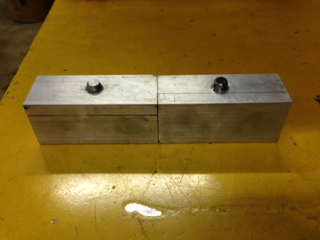
I think the new aluminum blocks i made will be fine. The ones that i purchased where cast units and had some design flaws that i think is what caused them to crack. The bottom clearance hole in the lowering block was far to oversized and deep. This caused a big stress concentration and when i tightened them down the block deforms to take the shape of the leaf spring pack it's being tightened against, which is a slightly curved surface. The news ones should be much stronger and less prone to cracking. If not, i'll make some out of steel. -Chris
-
I believe the mounting on your truck would be the same as on my '52. I had to replace those rear leaf spring frame mounts and i got mine from this place, http://www.srpmstreetrods.com/srpm/1939-47-dodge-truck-1939-41-plymouth-truck-rear-shackle-hanger-ea--ff8080813da289a3013ddae2fad529b6-p.html Kind of pricey but i couldn't find any good used ones. Maybe if you have access to machining equipment you could make your own? Im not sure how difficult that would be. -Chris
-
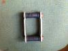
It was really easy. The shackles I bought were an after market replacement made back in the day. They fit 35-49 dodge and Plymouth passenger cars. If you look at the pic I posted there are two rubber bushings at the top of the shackle and two at the bottom. Theses just slide into the frame mount and leaf spring eye. Then a bolt passes through the center of the pair of rubber bushings to hold it together. Hopefully that makes sense. If not I'll draw a sketch and post it.
-
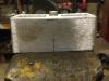
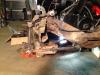
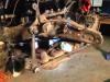
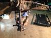
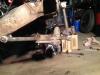
So i made a little bit more progress over the past few weeks. Awhile back i had bought some 2" lowering blocks for my car from Butch's Cool Stuff. I decided i wanted to install these finally, so i undid the spring U-bolts and installed each block. Every thing went pretty smoothly until i was done and had the car back on the ground. I was crawling around underneath it and noticed that one of the lowering blocks cracked in half while i was tightening down the U-bolts! I wasn't too happy about this so i decided that i needed to pull the block out and make a new one. Well once i disassembled the rear again i then realized that both shackles where totally shot, and i had tons of excess play in the rear end. At this point i realized i opened up a can of worms, since it was already open there was no turning back, i had to fix it right. In the end it was worth it... I spent the next couple days taking the leaf springs out. That turned out to be one hell of a fight. I ended up cutting the passenger side out so i could remove the bolt that attaches the front spring eye to the frame. The driver side shackle bushing that passes through the frame mount would not come out (FYI, this bushing is LEFT HAND THREAD). I needed to use the oxy-acetylene torches to heat up the mount to get the thing to budge. This led to having to drop the gas tank, i was scared i would blow myself up. Good thing i did cause the tank had a crack in it on the top. So after a lot of cussing, penetrating oil, and the torches, my leaf springs where out. This entire time i was crossing my fingers that i could get replacement spring packs made since i had to butcher the old ones to get them out. This turned out to be a blessing in disguise cause i got to fix a bunch of problems that i now don't have to deal with for a long time. I called up St. Louis Spring and ordered two new leaf spring packs. I brought my gas tank over to a local guy who repairs radiators, he sealed up the crack and pressure checked it. I ordered some 2"x 2" aluminum stock from McMaster so that i could make new lowering blocks. I also converted the shackles that i am using from the "Silent U Type" to the kind in the attached picture. I really had no choice because the passenger side bushing frame mount was badly worn. Since the gas tank was out of the way i was able to tidy up some wiring going over to the fuel sender and tail lights. Sorry for the long winded post. I haven't updated the thread cause i was busy working on the car. -Chris

-
I just got new leaf spring packs for my 39 Plymouth coupe from St. Louis Spring. They did a good job and made them fast. It was about $150 each.
-
I've never heard of that guy. From reading the info on his site he makes it seem like he has after market pieces from the 40-60s. Once those are gone he doesn't have any more. So I'm not certain that he actually fabricates them. For $85 it sounds like a good deal. Having a metal shaper make some for your car will cost much more than that. 20 gauge steel sounds kind of thin, I know most all the body panels on my 39 Plymouth are 19. -Chris
-
I made some decent progress this past weekend. I made a new set of battery cables, got my re-wire job 95% complete, finished putting together the entire front suspension, finished the brand new brake lines, and new fuel lines. Nothing is really to picture worthy but i'm really glad the lines are done with. That's by far the part i like the least. Soon i'll be able to run the engine. -Chris
-
I just made a set of cables for my car this past weekend (6 volt system). I went to the local welding shop and bought some 2/0 cable and heavy duty copper lugs for the ends. Then to NAPA and bought some battery terminal connectors. They came out nice and were not very expensive. -Chris
-
Best wishes Don!
-
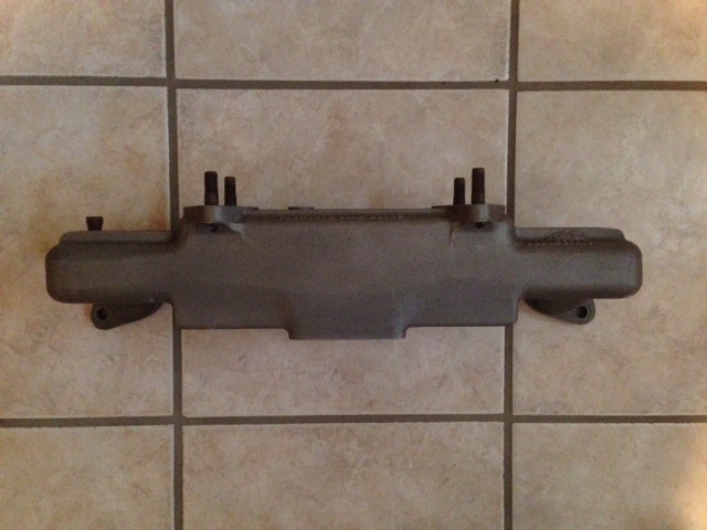
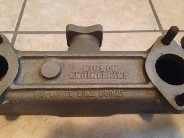
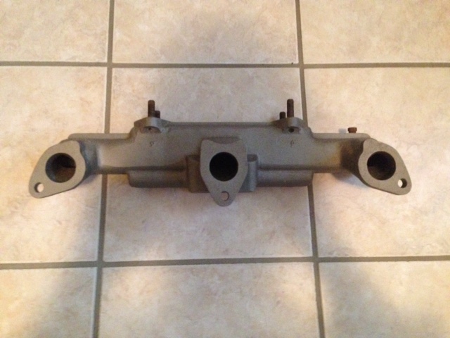
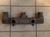
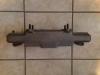
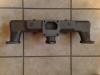
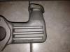
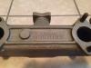
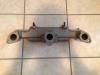
I scored this Nicson dual carb intake on ebay last week. It looks to be in really good condition, doesn't look like it's ever been used. This will go on the '39 at some point and possibly a dual exhaust that i fabricate myself. -Chris
-
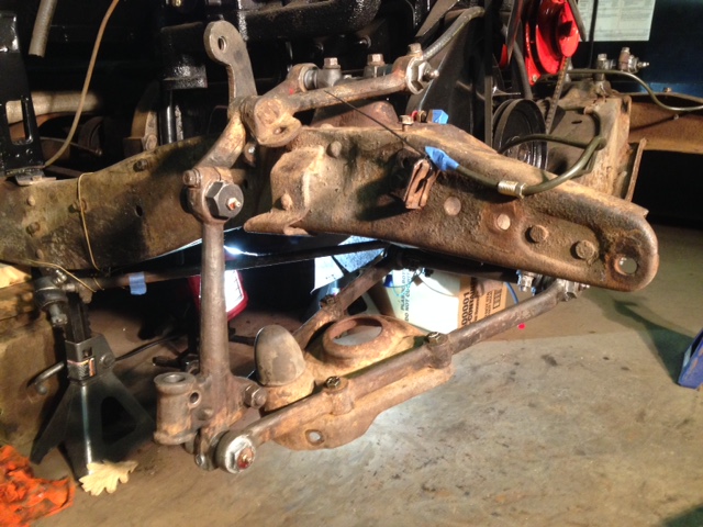
I had some time over the past couple days to start re-installing the passenger side front suspension. I was able to fix the grease zerk that broke off of the lower control arm bushing. I drilled it out and tapped it for 1/8 NPT, worked like a charm. Now i still need to finish installing the spindles, king pins, coil springs, and wheel assemblies on both sides. Im happy to say that the suspension feels really tight and smooth now. It also really wasn't that hard to assemble it without the special tools that are in the service manual. It just takes some careful measuring and being sure to tighten things down evenly. Does anyone know if there's a torque spec on the upper control arm bushings (pic 5 )? Thanks, Chris

-
Nice man, looks like you're plugging away! -Chris
-
Thats a really good point you bring up. Its really important to tack the panel in A LOT of places before starting to weld. I usually try to put my tacks about 3/8" apart. The backing with a piece of copper is also a good idea on areas with less than ideal gaps. When TIG welding i always try to back the weld area with copper, it helps to purge the back of the puddle with argon. Sometimes though its just not possible to get the copper back there. -Chris
-
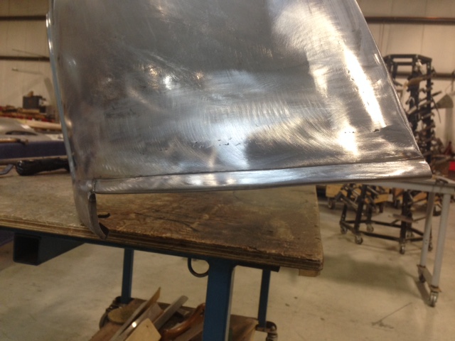
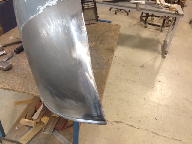
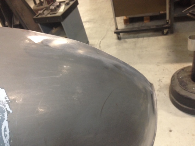
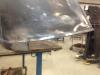
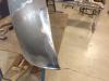
I agree with what's said above. I'd have to say though, MIG is slightly more forgiving with the material cleanliness. TIG is notorious for requiring extremely clean material for welding. Regardless of what process you use, MIG or TIG they both need clean metal. I prefer tig welding my sheet metal when ever possible. It gives you better control over the heat input to the panel and the welds are easier to dress. As Jeff stated above it's really the technique not the weld process!! Theres guys out there who do beautiful metal work and all they use is oxy-acetylene welding. Which to me gives you very little control of the heat input, at least not on the fly like tig. It's really important to use the least amount of heat as possible when welding sheet metal. Excessive heat causes more distortion (shrinkage), which then needs to removed by hammer and dolly work. Thats why i like tig so much, i can control the heat on the fly with the foot pedal. The techniques you use as you go along during the welding process is also real important. I like to weld a little bit (with tig i weld a few inches), then stop and grind down both sides of the weld. I use a 1/4" air die grinder with a 40 grit Roloc disc. I leave the weld just a few thousandths proud on both sides. Then i go to town with the hammer and dolly, this stretches the weld back out and helps to cold forge the weld into itself. Then i grind it flush on both sides and do a bit more hammer and dolly work. The goal here is to raise up any low spots. A neat trick that i use to find the highs and lows is to use a Sharpie marker and highlight the entire weld area. Then take a dulled file and pass it across the surface that you have inked. The file will scrape the marker off where it is a high spot and leave the marker behind where it's low. You now use this as your road map to finding the lows and bump those areas up with the hammer and dolly. Once the surface feels pretty good and you make sure it isnt all out of whack you can continue welding and repeating this process. At the end is when you can go back over the entire area and do the metal finishing. This requires more time with the sharpie, file, hammer, and dolly. In conjunction with the hammer and dolly i also use a shrinking disc. This is used to shrink any of the high spots down to give you a super smooth finish. If i was using mig i would do the same approach except instead of welding a few inches at a time, id jump around with a bunch of spot welds in various places. This helps keep the heat input to a minimum. Then just continue filling in with more spot welds till the seam is welded. Make sure to stretch the weld area as you go (hammer and dolly). I've attached some pics of fender repairs that i did on my '39 Plymouth Coupe. They where done with TIG and metal finished with the method described above. Regardless of the weld method i would definitely make sure you don't have any pinholes in your welds. This is where people run into issues, they coat with bondo and forget about the small pin holes that continue to let the moisture in. This will cause the patched area to show down the road. They make a filler called "All Metal" which is supposed to be really good and fill any of the pin holes and lock out all moisture. Heres the link: http://www.amazon.com/USC-14060-All-Metal-Specialty-Filler/dp/B0082LFAI6 So to answer the original posters question, i don't think you need to tig your panels to have them turn out quality. If you just take your time and pay attention to what the panels are telling you, how they are moving and reacting to the heat (hopefully not much) you'll be alright. If you're up for learning a new skill then maybe try out TIG. It's not as hard as it seems and the welders really aren't all that expensive any more. Plus you dont need anything big to weld sheet metal. If you want more info on the process or have any questions feel free to send me a PM. Good Luck, -Chris


-
Sometimes you just have to do what works and it sounds like JB Weld did the trick!
-
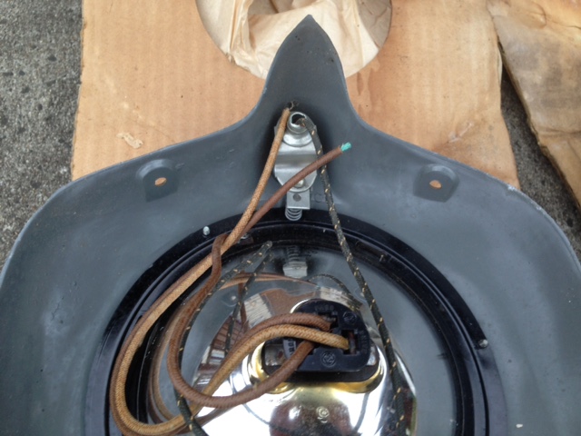
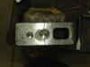
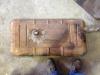
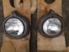
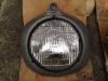
I'll have to look into the bushings and see if they can be tapped. I didn't know they made short zerk fittings, that'd be handy. I made a pretty good score today. Someone told me of a fellow who had an NOS Arrow headlight conversion for my car. The best part was that he was only 20 minutes from my house. This conversion kit allows you to switch over to round sealed beam headlights. I'm real happy i got to pick these up, i think they are pretty rare. The little bit of googling i did the other day didn't turn up much info. I've attached some pictures. -Chris
-
Thanks guys. I'm not sure it'll be possible to tap that for a zerk fitting. A regular 1/4-28 zerk will stick out into the inside of the bushing and could interfere with the pin that the bushing is threading onto. I'm assuming that's why these bushings have the zerk pressed in. That way there's nothing protruding to the inside of the bushing. -Chris
-
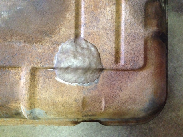
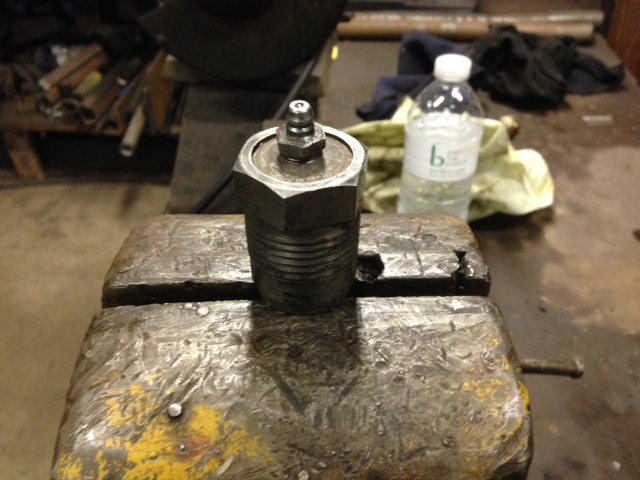
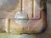
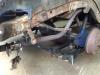
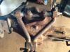
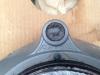
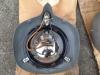
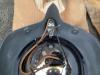
I made a little bit of progress today on re-assembling the front suspension without the special Mopar tools shown in the service manual. All in all it went well and really wasn't that hard to do.You just have to be sure to take your time and tighten things down evenly. I used anti-seize on the outside of the bushings that wont see any grease. I also pre-greased the bushings a little bit before assembly. This actually back fired on me on one of the "lower control arm bar bushing." I must of packed to much grease in there and when i tightened it down to the 165 ft-lb spec the force of the compressed grease blew the grease fitting right off. This has never happened to me before but now i know, and now i have to buy another bushing lol. I attached a picture of the busted bushing. The good news is that the drivers side now feels really smooth going up and down and there is no side to side slop like before.The car should drive so much better after this. I still haven't re-installed the king pin, wheel/ brake assembly yet. I will put the passenger side together next. Thanks for looking, -Chris


-
1940 Plymouth P10 Deluxe - Front end removal as 1 piece?
1952B3b23 replied to Bear40's topic in P15-D24 Forum
You can start a build thread on here, the same way you did this one and document your progress. It's a good way to archive your journey not only for yourself but also to hopefully help someone out in the future. You can post as many pictures as you want and ask questions/ get advice. It takes some effort but in my opinion it's worth it. Good luck and nice car. -Chris -
Nice looking car and some good progress! -Chris
-
So here are my thoughts on replacement panels. I've never purchased any as i really love metal shaping and make my own. There are many suppliers out there that cut corners when making "reproduction" pieces. Either the panel will not have enough crown, missing details (joggles, beads, bends, etc.), or other details. In my mind these are important details and shouldn't be missing. They impact the overall fit and finish of the panel. What the buyer does need to remember is that the supplier more than likely based his replacement piece off of the best original he could find. Which means that from one vehicle to the next there might be slight variations that make it necessary to tailor the patch panel to fit. These vehicles are 60 plus years old so who knows what kind of damages and repairs its gone through in its prior life. Even when new the cars weren't exactly the same from one to another. All of these variables make it really hard to make a patch that fits 100% every time. The only way to get a panel that fits exactly to the vehicle you are working on is to use that car as the basis for the pattern. If one doesn't have the skills to make this happen then its best to bring it to a metal shaper to have the work done. Obviously this can be mighty expensive so its not an option for lots of people including my self. Now this reply isn't meant to bash anyone or stir up any trouble, it's just my 2 cents on replacement panels. To answer the original posters question, if you're feeling adventurous and want to learn a bunch you can try making your own. You can even buy a cheap Woodward fab bead roller and put the beads in the floor pans your self. If i remember correctly the floors in these trucks are just flat with strengthening beads? They're really not that hard to fabricate. If you go the route with the bead rolling all you'll need for material is 18 ga sheet. Good luck, Chris