


1940 Dodge VC
-
Posts
55 -
Joined
-
Last visited
-
Days Won
3
-

Laycock J-type Overdrive
1940 Dodge VC replied to 1940 Dodge VC's topic in Mopar Flathead Truck Forum
This can be solved without changing the brake reverse light switch. Place a relay in the brake reverse light circuit to disengage the OD whenever the reverse light is engaged. Here is a description of the circuit--My assumption is that the power to the reverse light switch comes from a fuse to the reverse light switch, and from there, it goes to the reverse lights or ground. Power to the OD: Run power from your OD switch to pin 30 on a typical automotive relay (12v--though you may be running 6v, in which case, you'll need a 6v relay) . From the NC (normally closed--or the de-energized side) of the relay (labeled position 87a) run the wire to the solenoid on the OD. This setup powers the solenoid when the the switch is engaged. NOTE: In some applications, the OD switch is connected to a separate relay that powers the OD. It is the power to the OD that needs to be connected to pin 30. Now for the reverse light switch: Route the + reverse light switch wire to the relay coil (85). Run a separate wire from pin 86 to ground (instead of routing the wire to the reverse lights). The coil has enough resistance that only a trickle of power will flow through the relay when it is energized--not enough to light up the reverse lights--I'll get to that in a moment. Now, any time the brake light switch is energized, the relay coil is energized and the relay will flip to NO (open), disengaging the OD solenoid. Reverse lights: If you are planning on installing or using reverse lights, you may need a separate solenoid... Here is a link for relay information: http://www.gtsparkplugs.com/intro-automotive-relays.html -
Laycock J-type Overdrive
1940 Dodge VC replied to 1940 Dodge VC's topic in Mopar Flathead Truck Forum
That's a great site! I'm thinking that JSabah has three options: 1) Connect the overdrive directly to the transmission using a correctly sized flex disc or flex coupler--The overdrive would have to be aligned with the centerline of the splined shaft of the transmission. 2) Replace the forward u-joint with a CV joint that could handle his load, or 3) position the overdrive farther back, connected to the transmission through a jack shaft. (The third option is how mine is set up). -
Laycock J-type Overdrive
1940 Dodge VC replied to 1940 Dodge VC's topic in Mopar Flathead Truck Forum
I'm thinking that the H.A.M.B. board should have some driveline experts that could give some wise input. Here is a general information site that will help with the geometry: https://4xshaft.com/blogs/general-tech-info-articles/driveshaft-angles Here is another site that goes into a lot of detail about custom setups. https://www.therangerstation.com/tech_library/pinionangles.shtml In both of these articles, the universals are paired on the shafts, that is, there is an input and output universal joint. They are also phased. In your application, the front universal is a single one, being used as a flex joint. The big question is whether it is okay to use a universal joint that way. The rest of the geometry isn't a problem so long as things are parallel and the angles are within the correct limits. Its that first universal that has me puzzled. -
Laycock J-type Overdrive
1940 Dodge VC replied to 1940 Dodge VC's topic in Mopar Flathead Truck Forum
I just re-read your post. On my setup, overdrive is parallel to the transmission. Parallel, but offset so that the universals can be flexed correctly. My setup has a jack shaft between the overdrive and the transmission, so it is a little different in that sense. The overdrive had to be parallel to the transmission so that the universals would have the same degree of offset. As I recall, that was important to keep the setup balanced. Since your setup doesn't have a jackshaft, there will be some different rules to follow, and that's where the driveline experts will be quite helpful. -
Laycock J-type Overdrive
1940 Dodge VC replied to 1940 Dodge VC's topic in Mopar Flathead Truck Forum
That's a beautiful stetup and restoration! I don't have torque specs per se, though I am quite certain there is significant torque on the unit. Newton's 3rd Law... whatever torque is applied to the drive shaft will also be applied to the overdrive ?. The rubber isolation bushings on my setup are fairly stiff. Four bolts in front and two in the back. As to the angles-hopefully a driveshaft expert can chime in on this thread. I'm a little rusty on what the angles were. I do know that the geometry is critical to a balanced, smooth, quiet, trouble-free ride and to the longevity of the universal joints. I had help on that part from a driveshaft specialist in the area. -
Laycock J-type Overdrive
1940 Dodge VC replied to 1940 Dodge VC's topic in Mopar Flathead Truck Forum
The short answer is yes... if you are running the 12v solenoid. 6v versions were also made. You could contact a Volvo dealership (or GearVendors--who owns the rights to the Laycock ODs) to see if a 6v version is available for for your OD, or you could use a 6v to 12v step up converter to send 12v to the solenoid without changing the vehicle's voltage. As to positive or negative ground--it shouldn't be a factor. For the 12v solenoid: The resistance is unofficially listed as 17 ohms. Based on 17 ohms, the 12v circuit would consume 8.4 watts and draw 0.7 amps. If you run the 12v solenoid at 6 volts, then the solenoid would only draw 0.35 amps--2.1 watts of power. You would drop from 8.4 watts to 2.1 watts, and the solenoid probably wouldn't engage. If you have a 12v solenoid but your vehicle runs on 6v, then you could put a 6v to 12v step-up converter in the circuit line to the solenoid. These converters are fairly inexpensive, running somewhere between $15 to $45. Just make sure that it can handle the wattage. Here is one on Amazon that could work for you: https://www.amazon.com/DIGITEN-Converter-Regulator-Waterproof-Module/dp/B019GY2FLW/ref=sr_1_5?crid=1UE2OHRME4KFY&dchild=1&keywords=6v+to+12v+step+up+converter&qid=1610727027&s=electronics&sprefix=6v+to+12v+ste%2Celectronics%2C167&sr=1-5 -
Laycock J-type Overdrive
1940 Dodge VC replied to 1940 Dodge VC's topic in Mopar Flathead Truck Forum
It is August 2018 and I've been running the overdrive for three years without a bit of trouble. Once in awhile people ask how I like it and I can say, without hesitation, that it is fantastic. The truck works like it originally worked (well, it is quite a bit safer-- I switched to disc brakes) , and with the press of a button, reduce the rpm's by 25%--so I can go modern speeds without blowing the engine. The one upgrade that I made was to attach a sensor to the clutch so that whenever the clutch is engaged, the overdrive shifts down (shuts off). That has turned out to be pretty handy for downshifting as I come to a corner (I simply press the clutch pedal half-way down and the OD disengages, shifting down by 25%), and for having a middle gear between 2nd and 3rd. So I go 1st, 2nd, 2nd OD, 3rd, 3rd OD. The clutch switch shifts the OD back to the off position between 2nd OD and 3rd. It also insures that the overdrive is never engaged in reverse or when starting in 1st gear . -
Who Is Actually Driving Their Vintage Mopars?
1940 Dodge VC replied to 55 Fargo's topic in P15-D24 Forum
Here is my daily driver: a 1940 Dodge VC pickup. It sports a 201 ci engine, disc brakes and an overdrive, among other things. Most recently I used it to haul scrap metal to recycling and sheet rock for construction work. With the overdrive, I can do 70 on the highway, though I usually hold it between 60-65. Yes, the 201 is wimpy and maybe someday I'll swap it for a 230--if I run into a bargain. Today I worked on the headlight circuit and fuel gauge, both of which got neglected when I upgraded the wiring. It is a blast to drive, and I never cease to be amazed at the positive attention it attracts.
-
52 b3d "Little Blue Truck"
1940 Dodge VC replied to jpartington's topic in Mopar Flathead Truck Forum
Just saw your post about the snow--I'm in Minnesota, too. We didn't get much snow here in west central Minnesota. Just a dusting on top of the couple of inches that fell on Monday. I've been watching your hood ornament excitement--is the ornament you are putting on your truck from an earlier model? It looks similar to the one on my 1940. There is no pad under the ornament on mine. BTW, the heater in my truck is like yours. I think it was an add-on in 1940. There is only one knob--an unlabled (but lighted) rheostat to turn the fan on. It was clamped onto the lower lip of the dash. The flow of warm air is regulated by opening doors on the heater box. There is no temperature regulator that I can see. And the defrost was on by default. -
Laycock J-type Overdrive
1940 Dodge VC replied to 1940 Dodge VC's topic in Mopar Flathead Truck Forum
If you get the o-ring kit, you'll also get some very nice images of how to rebuild the OD. It is a very simple procedure. There just isn't much to these units, and not much to go wrong unless you put the seals in incorrectly--generally, either the electric solenoid goes bad, or the hydrauling unit needs the o-ring kit. It is possible that the clutch material may wear out. The gears are pretty much bullet proof, unless they are sheared off by a load, and it would have to be a really big load... I've never heard of anyone blowing one up. I have two units and both seem pretty solid. There are a lot of warnings about putting them into reverse, so I'm going out of my way to see that it doesn't happen. I have a dash light that reminds me when it is on. I may add a brake or clutch over-ride as well. Maximum Overdrive has a schematic for a brake override to protect the OD. Anytime the brake is engaged, the OD shifts back to low. You could also put it on the clutch, which would be more useful, I think. Anytime the clutch is engaged, the OD shifts to low. If you are really enterprising, you could mount a reverse switch to the end of your transmission. It would take a little engineering to find the right spot... Last thing before watching fireworks is that the hydraulic pressure is created by the input shaft RPM. It drives an eccentric cam that pumps a little hydraulic piston in the OD. The pressure that is created is used to shift from low to high. The electric solenoid, when engaged, routes the fluid to the pistons. The reason that the OD isn't used in lower gears is that if the shaft isn't turning fast enough, there won't be enough hydraulic pressure to shift or maintain the high speed position. That depends in part on the condition of the o-rings and the viscosity of the fluid that you are using. I've used it in 1st (accidently!) without any troubles. I especially like using it on 2nd and 3rd. Happy 4th, everyone! A great day to celebrate the birth of the USA! Our founders, when signing the Declaration of Independence, knew they were signing a declaration of war. They hoped it would lead to a new republic, of the people, by the people and for the people. I'm sure they would be amazed, and blessed, to see how freedom has changed the world. We say "thank you" to our founders, and thank you to all our service men and women--actively serving and retired--for giving us peace and protecting our independence. -
I put a Laycock J-type OD into the 1940 Dodge VC, and couldn't be happier. My students like to say, "It is the bomb!" I wrote about the process and included pictures, dimensions and links. Look up the Laycock overdrive thread in this forum. Those overdrives are fairly small and should fit into your car. You could mount it close to the rear end--or possibly directly to the rear end using the three tab rubber style donut mount.
-
Laycock J-type Overdrive
1940 Dodge VC replied to 1940 Dodge VC's topic in Mopar Flathead Truck Forum
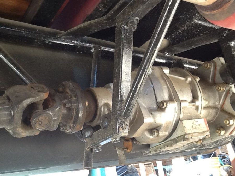
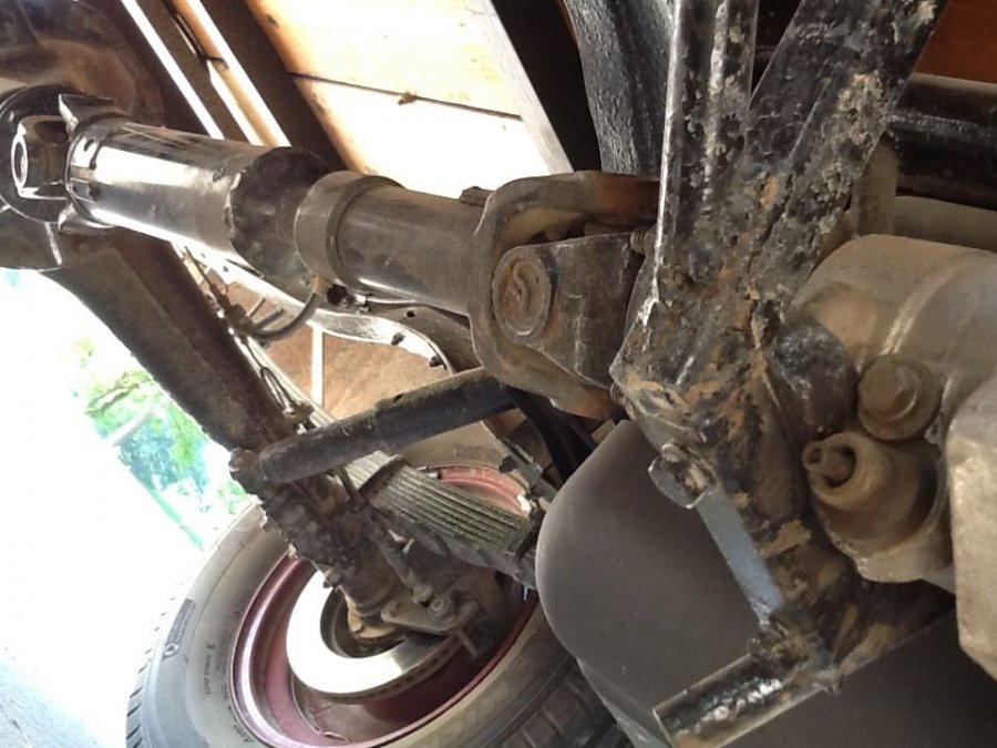
Here are some more pictures of the installation:


-
Laycock J-type Overdrive
1940 Dodge VC replied to 1940 Dodge VC's topic in Mopar Flathead Truck Forum
Happy 4th of July! Here are some notes about the overdrive: Laycock OD's come in several varieties. The designations of A and D were for early overdrives. J-type is the most common version and was used up through the 80's. The final model is known as the P-type. It is quite similar to the J-type and is used in some heavy duty applications, like racing. GearVendors bought the tooling rights for the P-type. (source: https://www.hemmings.com/magazine/hsx/2012/05/Laycock-Engineering/3712361.html) You can find a lot of information on the GearVendors website: http://www.gearvendors.com/install.html, and a testimonies about what it can handle. http://maximum--overdrive.com/index.html is another source for Laycock overdrive kits. They sell parts, including the shaft for $245. The site also features some electronic over-ride ideas and a kit. If you purchase an used overdrive, it is a good idea to replace the O-rings. I purchased a kit from Duane at ODGuru@kc.rr.com. My notes say that it cost $50. His diagrams and instructions are quite good. It is an easy job that can be done in less than an hour. There is a thread at http://www.mtfca.com/discus/messages/118802/120814.html with a discussion of fluid levels and types. My overdrive came out of a Volvo, so I am running Type F ATF. Obtaining an input shaft is the tricky part. The resellers on ebay usually pull the OD from the transmission leaving the shaft behind. You may have better luck finding a shaft at a local wrecking yard. Cut it off where it leaves the transmission. All you need is the part that fits into the overdrive and a couple of inches to attach the u-joint. You'll need the adapter collar (a 4" piece that connects the OD to the ) transmission. An enterprising person could manufacture the shaft. A spline on the end, an eccentric, a couple of clips and that is it. You might consider Maximum Overdrive's shaft. It may be less expensive than cutting one off of a donor car and welding a u-joint on. If I were to do it again, that's how I'd go. These were used in many, many vehicals. An extensive list of Volvo model transmissions noting the "electric overdrive" is at http://www.nuceng.ca/bill/volvo/database/sources.htm#[GRIMSHAW96]. Okay, the dimensions! These are for the Laycock J-type, mounted on a 1940 Dodge VC. Your frame measurements may (will?) be different. Caveat: These are approximate, taken from the mounted OD while lying on a creeper as the sun rose this morning. Length: 19” from u-joint mount to u-joint mount (3/4” custom mounting plate on front, 1/2” custom oil seal on mounting plate, 4” collar, 9 1/2” OD ) Height: 7 1/2” max Width: 7” max Mounting measurements: My transmission measures 12” from the bell housing to the universal mount. Shaft (with universals) from the transmission to the OD, 21”, from rear of OD to rear end: 25" From the top of the frame to the centerline of the OD: 8.5”. The bottom of the OD is flush with the gas tank. Passenger side to centerline: 20 1/2” on to the rear centerline, 18 3/4” to the front centerline (my frame angles in under the cab). Plenty of room to offset the OD without having to move the gas tank. -
Laycock J-type Overdrive
1940 Dodge VC replied to 1940 Dodge VC's topic in Mopar Flathead Truck Forum
We're insulating the shop right now--I'm excited to have a space that can be heated in the winter! Here are some quick responses. The civilian version of the VC did not have 4WD, though as I understand it, Dodge used that model as the basis for their military truck development, including 4WD. You'll need one reference line which can serve for both the vertical and horizontal measurements. Run a stringline along the top center of the frame. You can verify the centering by measuring across the frame at various points and taking half of that value as the centerline. Finding vertical: Find the flat spots on each component, use an inclinometer (Amazon sells one for $7-- IRWIN Tools Magnetic Angle Locator (1794488)) to verify the vertical alignment. You could also use a digital level. Horizontal: Use the stringline and use the input/output shafts to align to that centerline. That line can also be used to put in the parallel supports, which can be used as the reference points for all your measurements. I would focus on keeping the OD parallel to the engine. It sits about the same level as the fuel tank, maybe a bit higher. Will check tomorrow. Let me know if this makes sense. -
If there is strong spark, and gas, all that is left is flooded engine, timing or the rotor/cap position. If you didn't take the distributor out, then it should be firing on #1. Check your spark wires again. The 7 o'clock position is very close to the 9 o'clock position, so if your wires were off, you may have put them back on, one position off. (I'm speaking from personal experience ) Also check that the notch in the cap is aligned with the notch in the distributor body. After checking for flooding and the rotor/cap/wire positions, then check the timing as per Don's approach (thread #12 above). You could also try the static light method, which I prefer because it is easier for me to find the timing sweet spot. The static light method: Remove the cap. Wire a light between the points (or where the power goes from the distributor to the coil) and ground. Turn the ignition key on. The light should be on (unless the points are in the open position). Use a wrench on the generator pulley nut to slowly turn the engine in the clockwise direction (when viewed from the front). Watch the light. When it goes out, the points have opened. That is the point where the field in the coil collapses, sending a high voltage spike to the cap, through the rotor to what ever plug the rotor is aligned to. This is the point where the spark plug would fire. Now check the timing mark. It should be aligned to the factory spec. If it is at the factory spec, the rotor should be in the 7 o'clock position for #1. If the timing mark is not aligned with the indicator, then continue to turn the engine in a clockwise fashion until it aligns to the correct mark, then rotate your distributor body in a clockwise direction until the light goes off. Secure the distributor (there are two ways to loosen the distributor--the bolt that holds the distributor to the engine block, and the friction fit bracket that fits on the distributor shaft housing). Make sure both are tight. On the 201, factory timing is for TDC. You'll find a better description, with pictures, of the static light process by googling it. Now check the rotor position and cap again. Are these aligned for the #1 wire? Hope you don't feel like we're piling up on you. These things can be very challenging!

