
rekbender
-
Posts
115 -
Joined
-
Last visited
-
Days Won
2
Content Type
Links Directory
Profiles
Articles
Forums
Downloads
Store
Gallery
Blogs
Events
Classifieds
Everything posted by rekbender
-
The marks will look something like this.
-
what are the rules cruise in/ car shows
rekbender replied to Brent B3B's topic in Mopar Flathead Truck Forum
Their loss, not yours. I'll bet your truck would have caught the attention every kid there, and I 'll bet you would have let them climb on the running boards and sit in the cab, push the pedals and work the gear shift. I go to a local Friday cruise-in with three or for other guys. We all let the kids (boys and girls) examine our cars, blow the horn, and pose for pictures in the driver's seat. The pure glee they express is better than any trophy. I have vivid memories of my best childhood friend's father's late '40's Chevrolet dump truck because his dad let us play all over it. -
Did your solve your fuel gauge problem? I found this schematic and directions for testing a three wire Auto-Lite gas gauge (Dodge '39-'48) in a '49 Motor manual. It appears that current flows to the heating coil post at the rear center of the gauge, through the contacts on both the full and empty sides of the gauge, through the two bi-metallic strips, and then through the two wires to the sender. If I'm reading them right, the directions say pulsing current should be present at tank sender connections terminal 1 and terminal 2 as the bi-metallic strips heat and cool, and open and close the contacts. Depending on where the tank arm is on the resistance, the strips on both side of the gauge reach a different, but steady state temperature, and move the gauge needle. The gauge doesn't ground through the dash, only through the tank resistance. With current to the gauge, clean gauge contacts, two good wires to the tank unit, and a good tank unit with a good ground, everything ought to work!


-
Had my '49 convertible out today, so I tee'd a vacuum gauge into the wiper hose. With the cold engine idling (choke still on), and a damp windshield, the wipers cycled about 80 full wipes per minute at full speed. The vacuum gauge read 18 in. Hg or 45 cm Hg. The wiper motor on or off had no effect on the gauge reading. A few years ago I bench tested a rebuilt Trico KSB wiper motor for my '36 Plymouth. It ran at about 110 full wipes per minute at 16in. Hg with no load on the bench, and about 84 with the wipes on the windshield, so 80 may be a reasonable number for a motor in good condition.

-
You might want to check out this thread. http://p15-d24.com/topic/45614-shaving-a-218-head-vs-a-standard-230-head/
-
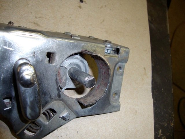
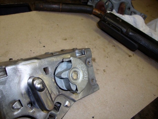
When the carb was apart, did you remove or disturb the throttle butterfly valve? I had the same problem with a B&B C6E2.The engine would idle on the adjustment screw, but the mixture screw had no affect - it idled best with the screw all the way in. Poor transition off idle - stumble, hesitation, stalling, fouled plugs. I tried everything I could think of - Installed a carb kit, checked fuel pressure, changed the float level, different initial timing, a different distributor, nothing helped. I finally read the rebuild instructions in an old Motor manuel. They stressed the importance of correctly centering the throttle butterfly making sure the transfer slot was completely covered. The C stamped in the butterfly visible from the bottom and toward the idle port. The C6E2 had been apart before. Sure enough, the transfer slot was partially exposed with the butterfly completely closed. This condition bypasses the the idle port/ mixture screw completely and dumps air/fuel emulsion below the butterfly. It's only supposed to happen off idle to supply extra fuel until the main metering system has sufficient air velocity to take over. I was not able to adjust the butterfly correctly as I think it had the wrong butterfly. Luckily, I had a parts carb, swapped butterflies, and that butterfly adjusted perfectly and the carb worked fine. If the shaft is loose in the throttle body, the butterfly may not center correctly. Hope this helps. The first picture shows the idle port and transfer slot below it. The second picture is the throttle butterfly closed and the transfer slot covered. The third picture is problem butterfly that couldn't be centered to close enough to block the slot


-
I don't want to hijack the thread, but I had the same problem with two identical canceling NOS Pathfinder 35768, 7 wire directional signal switches. One on a Ford and the other on my P18. I have a box of NOS 6V flashers that would flash the lamps, but none would flash the green indicator correctly - the green light would either stay on all the time or flash all the time the ignition was on. I gave up using the 3rd indicator terminal on the flasher and instead, soldered a 6 amp 50 volt diode to the wire to the right front and the wire to the left front directional lamps (positive diode leads to the lamp wires) and soldered the negative diode leads together, along with the wire to the green indicator. Now either directional lamp flashes the indicator correctly, with no feedback to the other side. It's work great for over a year. You could use the same set up to flash the factory indicator in the speedo as well. The correct 6V flasher for this Pathfinder (Auto Lamp 9000) switch is Pathfinder (Tungsol) 229D. I found one on eBay, but haven't needed to try it.
-
The history of Chrysler auto in Evansville.
rekbender replied to Fernando Mendes's topic in P15-D24 Forum
My '49 P18 was built in Evansville. It spent time in North Carolina, Missouri, and Nebraska, before I brought it to Ohio. Thanks -
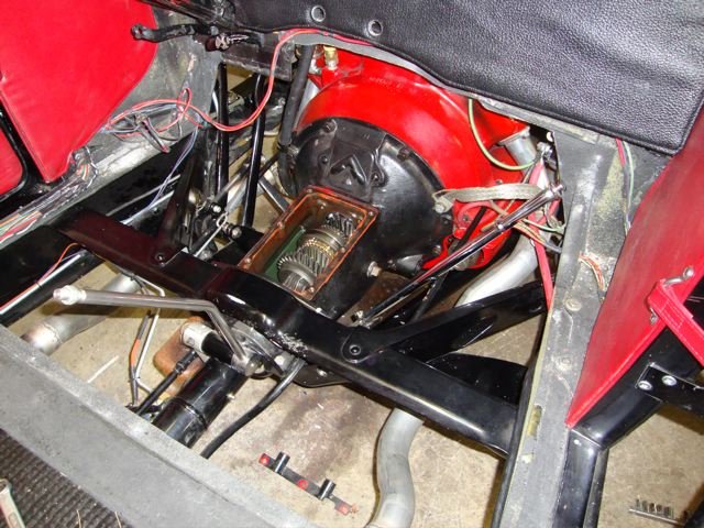
My lever was straight back and forth - back against the seat was direct, forward was overdrive. The linkage was uncomplicated and could be easily fabricated if you wanted to save some money. Since mine was in a stock '32 Ford chassis, the OD unit was incorporated in the torque tube - no external brackets. I bought the car as an unfinished project and the OD was already installed in the tube. It was beautifully done, probably by Mitchell

-
I had a Mitchell OD (26% overdrive) in a Ford flathead powered roadster a while back.It did require a second lever to engage, kind of cool in hot rod. It got lots of questions. It was synchronized and work perfectly, and had a speedo drive on the output shaft. I always used the clutch to go in and out. Not as slick as an R10, but you could split shift - I didn't. The Mitchell product seemed to be extremely well designed and built, but expensive. I don't know if parts are still available.


-
I found these a few years ago in a closed tire shop. Dynatrue tire truer and Atlas "Tune In" on car balancer. They were going to be sold for scrap. Of course I had to save them.


-
Who Is Actually Driving Their Vintage Mopars?
rekbender replied to 55 Fargo's topic in P15-D24 Forum
I'm a fair weather driver. The '36 was stored inside an old garage from 1957 thru 2005, and hasn't been wet in 60 years. The '49 is a 40 year old restoration and leaks in lots of annoying little places in the rain. I just drove it today, and now it's in for an oil change.
-
I had the same experience with my '36 Plymouth. '58 Dodge 230 with a '48 Plymouth 4bolt flywheel, '36 bell housing, '36 starter. It has worked fine for 9 years. At the time, I was unaware of the 230 crank flange difference, so I just blindly bolted everything together. Patmac, post some pictures of how everything fits. My '36 bell housing looks just like bones44's.

-
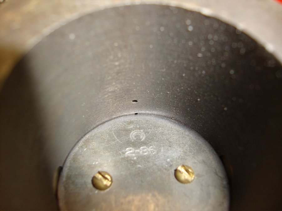
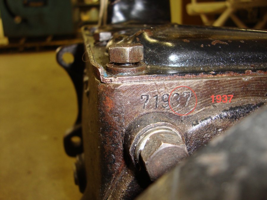
The transmission may have a number stamped at the top rear of the case. Pictures are of '35, '36 and '37 Plymouth transmissions. The last two digits of number on the left side appears to indicate the year the transmission was assembled. The model designation is stamped on the right side. PJ for 1935, P1 for 1936. I've seen build dates stamped on the front case edges of later 3 speeds. Could you post pictures?


-
Thanks for the info. The oil I used after replacing the bronze stop rings is rated GL5, although the label on the back says it's a suitable replacement for GL2/3/4. I purchased GL1 at Tractor Supply ($17.99 for 2 gallons) this afternoon, and since the car the car is on the rack now for it's pre-season servicing, I will drain the transmission and fill it with GL1 tomorrow. These were my last two NOS stop rings so I hope to make them last.
-
Is it the white metal synchronizer stop rings that are affected? How about the brass stop rings in the earlier transmissions? Any other information GL! versus GL4/5 would be helpful. I had a brass second gear stop ring fail suddenly and completely in my '49 transmission last summer - is this the result of the wrong oil? I replaced the stop rings and it shifts great, but I'm afraid of what's in the transmission now.
-
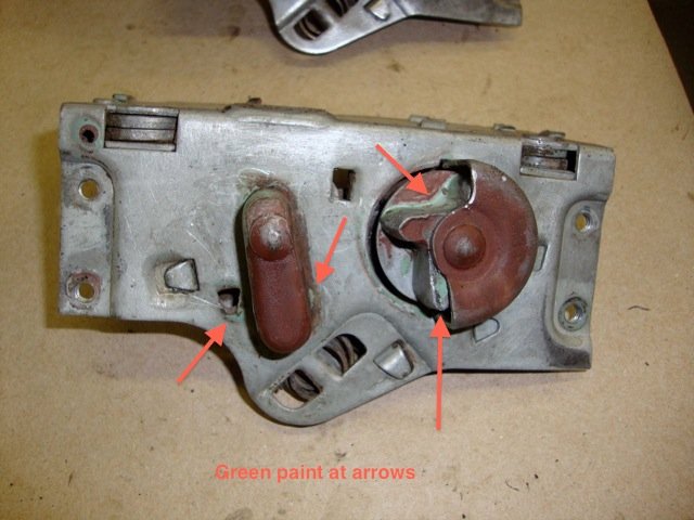
Just a guess, but I think the latch (lock) was painted. Yesterday I removed the latch from a 1951 or 1952 Plymouth convertible door. The inner door frame still has it's original mint green or Nile green paint. It appears that they assembled as much of the door as they could before painting, The latch goes in first, then the rear glass channel. The latch remote control rod was assembled to the door shell as well as the window regulator regulator, the door hinges were attached to the shell, and the door was painted. These components all were painted on this door. Then door glass, stops, vent window, handle, lock, even the little wedge on the door jamb were attached to the painted door. If the door and striker were adjusted prior to painting, I'd guess the striker was painted as well, but maybe not if final door adjustments had to be made later. There are traces of green paint on the latch rotor, but only on one tooth which makes sense as only it was exposed. If this door was a later replacement, who knows. There has to be someone here with an original paint car who can shed more light on this.
-
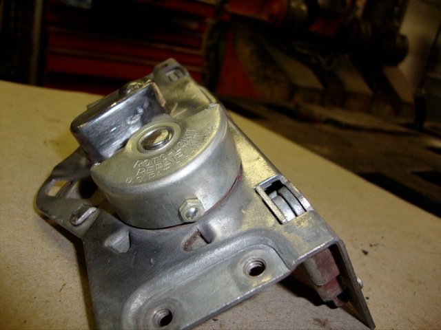
I forgot this picture - a tiny set screw and jam nut holds the cover. With my old, stiff fingers, I dropped the screw twice and almost lost it.
-
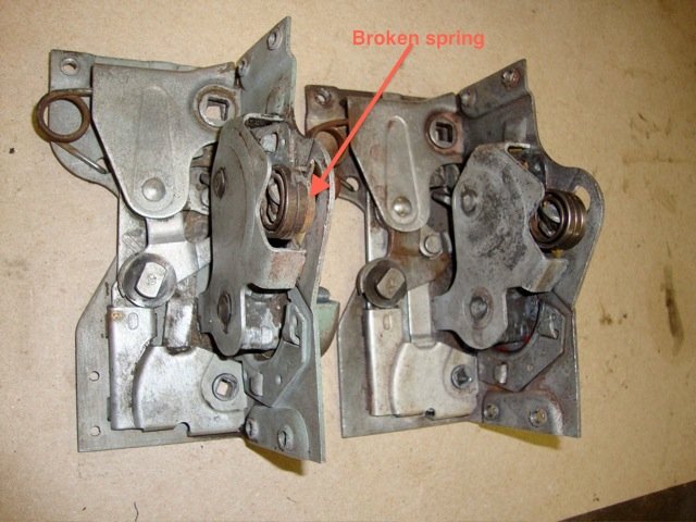
I replaced my driver's door latch rotor yesterday with the parts from an ebay Roto-Lokit kit yesterday - what an improvement! I went a little further and removed the latch so I could repair the protruding bar that slides over the striker and supports the door when closed. Both the bar and striker were pretty badly worn and the door didn't close or open smoothly. I welded up the worn area, and ground and filed it smooth again. The last step was installing a new striker. The door opens and latches like new. You might want to remove the latch and check for broken springs on the pawl that locks the rotor. I noticed the broken spring on a spare latch I'd planned to use. Luckily, the latch from the door was fine. Well worth the effort, just follow the directions - I used a cutoff wheel to remove the cap and rotor.


-
Point well taken. I've probably been lucky, but the NOS vacuum chamber on my '36 Plymouth has been functioning since spring of 2009. I put another NOS chamber on the IAT distributor ('51 engine) in my '49 last spring - so far so good. I would NOT rely on an NOS or NORS fuel pump today. Both of my fuel pumps have modern, alcohol resistant diaphragms installed. The raised loop in the steel vacuum line from the carburetor is supposed to help keep liquid fuel from collecting in the line, and the line is evacuated each time the engine is started, so maybe this has helped. I just bought spare IAT-2023RG NOS chamber on ebay last week - it was too cheap to pass up - which I plan to carry in the '49.
-
My Auto-lite book shows their part number as VC-2082R. There are two of these NOS on ebay right now. Bernbaum lists them as well. I've had great results with NOS Auto-lite.
-
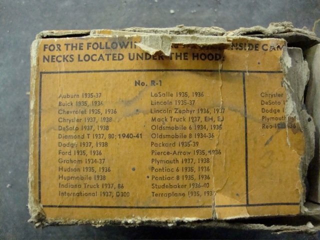
This old Stant Everseal box shows an R-1 radiator cap as correct for a 1938 Chrysler. Unfortunately, it's full of R-2's.
-
1938-1951 Autolite Parts Catalog
rekbender replied to Lloyd's topic in Forum Announcements And Feedback
Thanks for the download - excellent information. -
Auto-Lite Generator Part Numbers (1941 Plymouth)
rekbender replied to kklemm's topic in P15-D24 Forum
According to my Autolite Maintenance and Operation Manual (1950), generators GDZ-4801, A,B,C,D,E,F,G,H, K,Q,R,T all share the same specs. Output given is 8V, 35 Amps max, at 2000 RPM max. Regulator is VRP-4001A. Maybe the letter suffix has something to do with the pulley size or design, possibly the end frames were indexed differently? I have a GDZ-4801-A I could take some pictures of. -
Made this for my '36 Plymouth.


