


erikquick
-
Posts
8 -
Joined
-
Last visited
Content Type
Links Directory
Profiles
Articles
Forums
Downloads
Store
Gallery
Blogs
Events
Classifieds
Everything posted by erikquick
-
No spark issue... car died on the way home from getting gas
erikquick replied to erikquick's topic in P15-D24 Forum
Hey all, Made more progress. Some good news. It IS a 12-volt negative ground system. - the flasher relay had shorted out; I pulled it and things started looking "normal" again. - now I have 12V ignition coming in to the ballast resistor. - so, going to the + post of the coil is the (a) out from the ballast resistor, (b) to the electric choke, and (c) to the distributor housing --- which I still don't understand. - the - post of the coil was going to the starter solenoid, through that momentary button under the dash, which all seemed kinda dumb. So I moved it directly to chassis and took that switch out of the loop. so now, - on the coil goes directly to chassis ground. I pulled the distributor cap off and looked at the points. Was going to meter for continuity, but it started to rain. So, she's covered back up and I'll attack this again soon. More to come - thanks all! Erik -
No spark issue... car died on the way home from getting gas
erikquick replied to erikquick's topic in P15-D24 Forum
Yeah, happy to tackle that. Yes, no idea why and I’ve never touched that button. Weird, but it did... I’ve got a basic MECP certification and I’ve been around car electronics for 20+ years. But all modern cars, and never came across something this confusing. -
No spark issue... car died on the way home from getting gas
erikquick replied to erikquick's topic in P15-D24 Forum
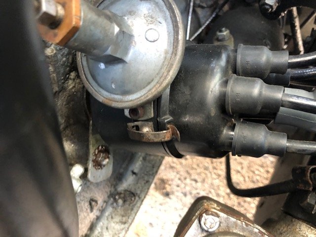
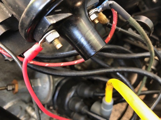
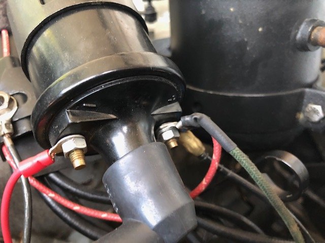
Update to all. I will need to look into the distributor (yes, it's points) to see if it's grounding out. However, I'm still confused about how this ignition coil is wired up. To be honest, I don't know anymore which side is SUPPOSED TO have the 3 wires to it and which side is SUPPOSED TO have ground. I have a positive ground system... I put my meter lead on the main ground wire to the engine and put my other lead on the battery terminals. I got 12V when one lead was on the negative battery post and the other on the chassis ground. With that being said (that I have a positive ground system), am I supposed to be hooking up the 3 leads to the (-) on the coil? Or the (+)? For more context, there are 3 wires together on one post of the coil. They go to come from: 1. a +12v source (it's a constant 12v although I think it should be ignition) 2. a wire that goes to the body of the distributor 3. a wire that goes to the carburetors (one wire splits to two) The other side of the coil has one wire. It goes to ground, but is on a momentary switch that is under my dashboard. When you push in the switch, it interrupts the ground. (IMG6108 is the switch, IMG6019 is the ground point for the momentary switch, IMG6110 is the other side of the momentary switch that goes to the coil) So confused! Thoughts?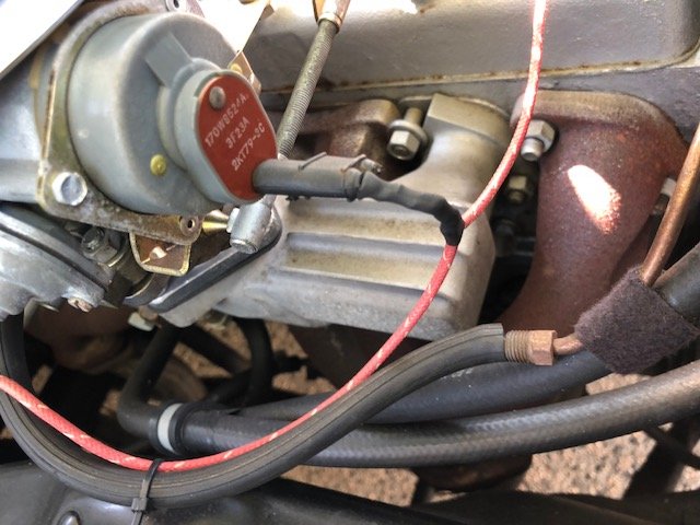


-
No spark issue... car died on the way home from getting gas
erikquick replied to erikquick's topic in P15-D24 Forum
Thanks, Merle, and all. So, more info... It's still a points distributor. I'll see what else is connected to those other 2 wires on the + coil, but I know one goes to the case of the distributor. My other test lead is on the batter y positive. When my other (neg) lead was on negative terminal, I had no voltage readings to the coil. And I have no idea if my coil is a 12V or 6V coil. And yeah, no idea why the flasher relay is wired in parallel to the wire at the input side of the ballast resistor. The original Plymouth service manual says nothing about that, and I would REALLY like to have this car wired the way it's supposed to be - as original as humanly possible. Whoever had the car last got it running (and it ran well before it died), but definitely seems to have been a bit of a hack electrical front. Irks me to no end. -
Good morning friends, I've got a little learning to do... I took the '52 out to get gas the other night. She ran fine after warming up. I filled up the tank and headed home. No drama. But then, she just died on me at a light. Turns out I was no longer getting spark to the coil (so I think). I'm a little confused about the way this ignition coil is wired up. The car has been converted to 12 volts, and that is all done nicely and neat under the dash. I put my meter to both the ballast resistor and the ignition coil to better understand where I might be losing juice. Turns out, there is power going to the ballast resistor, but it's a constant 12V - doesn't seem right. Shouldn't that be on ignition only? Anyway, then I metered the two posts on the ignition coil. Both look to be "positive ground" at rest with ignition off and the wires connected to the ballast resistor. Doesn't make any sense to me. Before I go crazy and start replacing parts (not that I mind new parts now that I am the new owner), I just need to understand how to diagnose my no-spark issue on a system like this. A few troubleshooting ideas are welcome. Pics below. Thanks!


-
Thank you. Yes, I was impressed by the love and care that went into this resto/mod. IMO very tasteful now, if anyone can help me figure out why I have no spark to the coil...


-
Thank you all! Yes, @JerseyHarold it is still the flat 6. Has an Offenhauer intake and dual carbs. Needs a little cleaning up and i’m still trying to understand the ignition system (converted to 12v) but it’s very clean and looks like it was well put-together. Past owner was a car collecter in North Carolina... I have his name somewhere.

-
Hey folks, So happy to have found this forum! I'm a proud new owner of a P23 - a 1952 Cranbrook coupe. Well restored a few years ago, and picked it up recently from Palm Beach. Transported to Long Island and hope to get it out cruising ASAP. Looking to contribute to the forum and learn a LOT more! Erik

