Kahunah
-
Posts
33 -
Joined
-
Last visited
Content Type
Links Directory
Profiles
Articles
Forums
Downloads
Store
Gallery
Blogs
Events
Classifieds
Everything posted by Kahunah
-
I have the 100 amp GM alternator in my '41. When I rewired the car I put fusible links on both ends of the charging/load circuit. I also bridged the terminals of the ammeter with a fusible link. The gauge still works though, I could be wrong, in theory only showing half the actual current flow. I have peace of mind knowing the circuit is absolutely protected.
-
If you don't have the windshield, just trace the opening onto a piece of cardboard. Bring the pattern and the gasket to a glass shop that can cut flat laminated. They will be able to make the necessary adjustments to the pattern to allow for the gasket. (I ran a glass shop for years.)
-
When I went through the wiring, my ammeter backing plate did have some rust and evidence of arcing. Yours may be okay, just give it a thorough look.
-
Just some preventative maintenance, you should clean up the ammeter backing plate. Rust jacking can short the posts to the gauge backing plate.
-
I simply bought one 22" blade. I took the original blades apart. You just have to carefully bend one set of tabs in order to slide the insert out. I reused the metal supports from the original blades and cut the new blade to fit. Slide it all back together, carefully bend the prongs closed and you have two new blades super cheap.
-
I don't know if '54 is the same, but on my '41 the fuse is right on the headlight switch.
-
If connected this way, won't the pilot light stay lit? I did this once on a Desoto and the pilot light stayed lit with the signal switch in the neutral position. It seemed the load of the light was not great enough to cause the element to heat up. It did flash when either signal was activated. Wasn't a big deal though.
-
 For the gas tank, if it's the same as '41 the nuts for the straps are through the trunk floor.
 -
I used the Rusty Hope disc conversion and the ECI master cylinder kit on my '41 P12. I don't have a booster on mine, and honestly I really don't think one is needed. The pedal feel is firm but not overly hard. You don't have to stand on it to get a good braking response. I don't think there is enough room to fit a booster without major frame modifications and I did not want to mount the booster and master on the firewall.
-
That is really good to hear. I have done the front disc swap, 12v conversion and new wiring harness throughout. I have a LA360 that I had considered swapping in but, the more I drive it with the flat 6, the more I love it. I really think the OD and rear swap will be the cat's meow for me.
-
I'm very interested in this swap. I have the A833OD and an 8.25 with 3.55 gears from a Cherokee on the garage floor just itching to see the road. I really want to keep the flatty but want the OD to cruise.
-
I used Rusty Hope's brackets for the disc conversion. All of the other parts required are off the shelf and he sends a detailed list with part numbers. IIRC, I spent right at $500 for the conversion. The master cylinder is off the shelf and I bought the pedal conversion kit from ECI. It works perfectly.
-
Wonder how many bad words were said when he tripped over the exhaust pipe!
-
The proper sealant to use between the gasket and pinchweld is a bedding compound. 3M #08509 is the one I used when I did glasswork for a living.
-
On my '41 P12 I used Rusty Hope's disc brake kit and the master cylinder kit from ECI. I also installed new shocks. I'm very happy with the results. All wearable parts are easily replaced with off the shelf items.
-
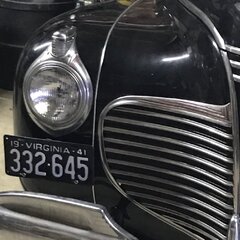
37 Chevrolet. 38 had the same body line in the door but the opening in the side of the hood was longer. The hood ornament looks like one my grandfather had on his car but it was an aftermarket item.
-
what to do about hard to find front brake parts/manual disk brake?
Kahunah replied to mburtis's topic in P15-D24 Forum
I used the Rusty Hope kit on my '41 for the front disc set up. . I know some have had issues with the ECI master cylinder kit but my experience was straight forward and quite easy. The brakes work perfectly. -
Yep....I had them installed above the toe board facing up and they never worked right. I saw a diagram in the assembly manual with them facing down below the toe board. They only seal when the pedals are up....crazy!
-
I just replaced the gasket on my '41. Loosen the screws accessible through the vent. On the inside is a nut and bolt that attaches the vent to the handle. The rod is serrated for adjustment. The vent is now removed from outside. It was not hard at all. I took it apart because I had some surface rust I wanted to treat before it became a problem.
-
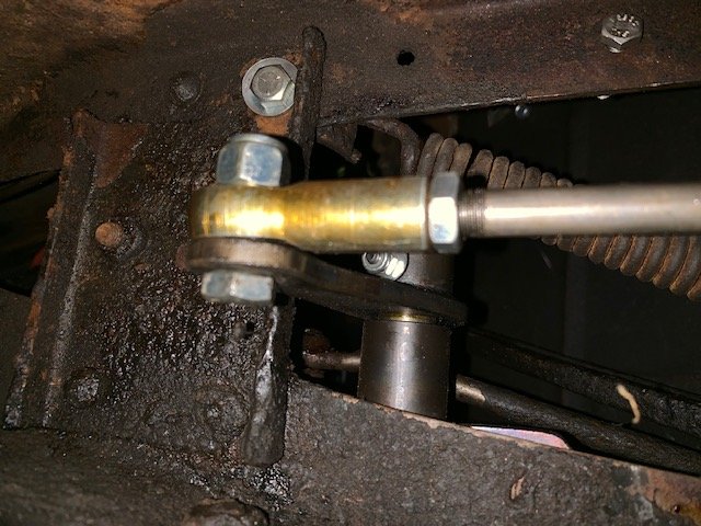
This is the location and bolt I used. The picture is from under the car looking up towards the m/c rod. You can see the spring and bracket above the frame. Hope this helps!
-
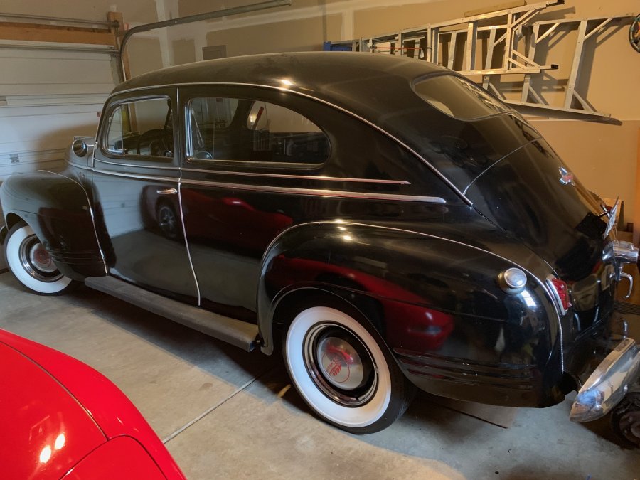
I'll get a picture of it as soon as I can. Here is a pic of the car.
-
For every 1lb of pressure the boiling point of water is raised @3 degrees (F). The thermostats are 160* and the system runs at about 3lbs. The boiling point is thus @221*. (The temp gauge on my 41 pegs at 220*) Using a higher pressure cap would raise the temperature of boil over but may lead to other problems, such as leaking welsh plugs or water pump shaft. Modern vehicles require a higher pressure system because the higher operating temps are necessary for the emission systems. As long as your cooling system is in proper working order there really is no reason to use a higher pressure cap even with a new radiator.
-
On my 41 P12 I moved the bracket that holds the spring. Just towards the front of the vehicle on the frame is a rivet that goes through the cross brace. I drilled out the rivet and bolted the bracket there. Works perfectly and clears everything.
-
I believe the correct measurement would be a 3.048 meter pole.....
-
I'm pretty sure on my 41 the float was towards the left side of the car but its been awhile. I'm sure someone will correct me if I'm mistaken. The two wires at the sender are a path to ground. There is varying resistance on each circuit with the position of the float arm. That in turn actually heats metal strips in the gauge that moves the needle.