STOP what you are doing and fix those brakes!
Introduction
Your new P15 project just rolled up on the flatbed tow truck. The
previous owner had been pretty honest about the condition and as the
tow driver unloads you remember his comment "Oh and the brakes are a
little soft". You hop in, and as your friends help push the car up
the driveway you tap the brake pedal. It goes to the floorboard and
stays. As the garage door loom closer in the rear view mirror, you
pull the emergency brake and nothing happens. Suddenly you stop,
saved by a rock quickly thrown behind the rear wheel. Definitely a
little soft.
Brake overhauls should be one of the first projects on your
restoration list. Working brakes permit you to safely control the
car in the shop area. The brake design used in this era of flathead
mopars are notorious for wheel cylinder leaks and difficult to
adjust brake shoes because of the non-servo design. With a single
chamber master cylinder a brake line failure takes out the entire
brake system. Since our project P15 needs a full brake system
overhaul we will do it right ones and have years of safe service.
First you will need to source needed brake components. They are
still available from a variety of sources in NAPA if you have the
correct part numbers. You will also need a factory service manual.
Plan your time realizing a full overhaul will probably stretch over
two weekends.
|
History and Terminology
Chrysler acquired a new hydraulic brake technology
from Lockheed in the mid-thirties. This design used a double
anchor, non-servo design. In servo design brakes one shoe "helps"
the other by forcing the secondary shoe against the brake drum.
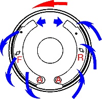
Non-servo brakes have a shoe attached at one end, called the heel,
to an eccentric anchor bolt (the "major" adjuster).(Red
"A"). It allows the shoe heel to be adjusted toward the
brake drum. A second eccentric cam ("minor" adjuster) is used to
move the other end of the brake shoe ("toe") outward to compensate
for brake shoe wear. As seen in the first drawing it is impossible
for each shoe to "help" the other because both are anchored. The
forward shoe (Red "F") is self-energizing, that is, the free end
of the brake shoe ("toe") is forced into contact with the
revolving brake drum (Blue arrows moving outward into the brake
drum). As it moves toward the anchored end of the brake shoe
friction tends to force the shoe even tighter against the brake
drum. The reverse shoe (Red "R") is not self-energizing (Blue
arrows moving into the shoe).
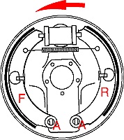
This is true for single wheel cylinder setups usually found on the
rear drums. (Second Drawing)
Both P15s and D24s use a front dual cylinder setup with a single
end wheel cylinder for each shoe.
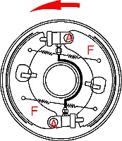
The advantage of this configuration is both brake shoes are now
self-energizing, providing additional braking ability.
|
The Inspection
 Get
the car up on jack stands. I usually place two under the rear axle
and two under the frame near the front door hinge and just behind
the frame bend. Also pull the floor mat and transmission access
panel on the front floor. This provides easy access to the master
cylinder. First check the wheel backing plates for brake fluid
leaks. If a leak is present a oily stain will collect at the bottom
of the backing plates.Inspect the rubber boot on the master cylinder. Brake fluid presence
indicates the master cylinder is leaking. Also inspect the rubber
flex lines behind the front wheels and rear axle for crack and
leaks. Remember any failure of a line leaves you with no brakes.
Visually inspect all of the steel brake lines. The original stock
steel ones will be rusted on the outside. Pay close attention to the
lines coming out of the master cylinder. The springs on the lines
protect them from damage but also provide a great spot for rust to
grow. Get
the car up on jack stands. I usually place two under the rear axle
and two under the frame near the front door hinge and just behind
the frame bend. Also pull the floor mat and transmission access
panel on the front floor. This provides easy access to the master
cylinder. First check the wheel backing plates for brake fluid
leaks. If a leak is present a oily stain will collect at the bottom
of the backing plates.Inspect the rubber boot on the master cylinder. Brake fluid presence
indicates the master cylinder is leaking. Also inspect the rubber
flex lines behind the front wheels and rear axle for crack and
leaks. Remember any failure of a line leaves you with no brakes.
Visually inspect all of the steel brake lines. The original stock
steel ones will be rusted on the outside. Pay close attention to the
lines coming out of the master cylinder. The springs on the lines
protect them from damage but also provide a great spot for rust to
grow.
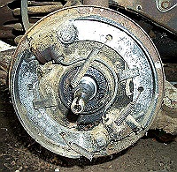
Starting up front pull the tires. Using a ¾? wrench, back off the
two minor shoe adjusters at 9:00 and 3:00 o?clock. Turn the wrench
up and towards the wheel spindle/axle to release the adjuster. When
the wheel freely spins remove the wheel bearing dust cover pull the
cotter pin, nut and washer. Pull the drum straight off the front
spindle. Be careful not to drop the outside wheel bearing as the hub
clears the spindle. Don?t be surprised if what you see behind the
drum is not a pretty sight. Usually the wheel cylinders will have
leaked on the brake shoes and return springs may be missing or
broken. Next check the inside surface of the brake drum. Any deep
gouges from a worn out brake shoe?
|
Rear Brake Drum Removal
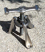 Unlike
most "modern" cars, rear brake drum removal requires a special brake
drum puller. These are available at most automotive tool rental
shops. Drum pullers that attaches to the rim of the brake drum
should never be used as they will permanently damage your rear brake
drum. Finding replace drums is both difficult and expensive.
Many tool rental shops have the correct puller for $30 to $40 a day
or you can purchase one for about $125 dollars. Once you have the
correct puller start by backing off the "minor" brake adjusters
using a 3/4 inch wrench on the back of the backing plate. The wheel
must turn freely. Next, remove the axle cotter pin and locking nut.
An air gun is very useful for breaking the nut loose. For safety you
may loosely re-attach the axle locking nut. This insures the drum
won't fly off the axle when it breaks free. Attach the puller to
three of the lug nuts and snug the puller against the axle.Using a
large hammer strike the puller arms until the brake drum breaks
loose. An air gun can be used instead of a hammer on the puller
adjustment nut. Once free off the drum and be sure to remove and
save the square steel key. I have seen posts recommending heating
the drum to help break it loose. I have never needed to heat a drum
and do not recommend it. It is very difficult to control the heating
and you may cause serious damage to the underlying components such
as axle seals or wheel cylinders. Unlike
most "modern" cars, rear brake drum removal requires a special brake
drum puller. These are available at most automotive tool rental
shops. Drum pullers that attaches to the rim of the brake drum
should never be used as they will permanently damage your rear brake
drum. Finding replace drums is both difficult and expensive.
Many tool rental shops have the correct puller for $30 to $40 a day
or you can purchase one for about $125 dollars. Once you have the
correct puller start by backing off the "minor" brake adjusters
using a 3/4 inch wrench on the back of the backing plate. The wheel
must turn freely. Next, remove the axle cotter pin and locking nut.
An air gun is very useful for breaking the nut loose. For safety you
may loosely re-attach the axle locking nut. This insures the drum
won't fly off the axle when it breaks free. Attach the puller to
three of the lug nuts and snug the puller against the axle.Using a
large hammer strike the puller arms until the brake drum breaks
loose. An air gun can be used instead of a hammer on the puller
adjustment nut. Once free off the drum and be sure to remove and
save the square steel key. I have seen posts recommending heating
the drum to help break it loose. I have never needed to heat a drum
and do not recommend it. It is very difficult to control the heating
and you may cause serious damage to the underlying components such
as axle seals or wheel cylinders.
If the drum is stuck usually the brake adjusters are not fully
retracted. If the car is drivable loosen the axle locking nut
1/8-1/4 inch (keep the cotter pin) and slowly drive it around a
couple corners. This will usually break the rust bond. If the shoes
are rusted to the drums and they wont turn you will need to remove
major adjuster. Remove the nuts on the anchor bolts that hold
the major adjuster on the backside of the backing plate. Drive the
anchor bolts toward the drum. When the anchor bolt shoulder clears
the brake shoe bracket the shoe will pull back from the drum
breaking it free and allowing removal. Our project P15 has all the
standard problems: cracked flex lines, rusted steel lines, leaking
master and wheel cylinders, broken and missing return springs, no
pads left on the shoes and one brake drum badly scoured from a shoe
bracket. It?s time to do a complete overhaul. I generally strip down
all wheels at once, but if you feel uncomfortable you won?t remember
how thing go together start with a single wheel. I also take the
approach all the mentioned parts will be replaced with new or
remanufactured parts. I feel this is the correct methodology for a
new project where you don?t know the history or quality of previous
repairs. |
Tear Down
Remember brake fluid damages paint! Have some denatured alcohol on
hand to clean up any accidents and a container to capture and store
old fluid. Starting with the rear, detach the brake line coming from
the rear axle. Capture any residual brake fluid in the line. Using
either a brake spring tool or large flat screwdriver, pop off the
brake shoe return springs. Wear eye protection and don?t put your
face down close as the can fly outward as the release. Remove the
two large anchor bolts at the bottom holding the shoes on the
backing plate. These anchor bolts are the "major" adjusters. After
removing the backing nut, slide the bolt out the front. Two steel
spacers will fall from behind the shoes. The anchors have a large
smooth shoulder, followed by a cup shaped retainer with a felt pad
inside. The felt is a lubrication wick. Once the anchor bolts are
out, the shoes can easily be removed. Two small bolts hold the
single wheel cylinder to the backing plate. With the parts all
removed check the seal where the axle passes through the backing
plate. Now is the time to replace is and it will guarantee a leak
won?t ruin your new brake job. Unbolt the five nuts and slide off
the backing plate. Usually an axle shim(s) will be behind the plate.
This is also a good time to inspect the rear wheel bearing
lubrication. Check the Tech Tips on Rear Axle Lubrication and your
shop manual for more information.
By the way, don?t throw anything away yet. Set them aside so you can
check the fit with the replacement parts.
Front brakes tear down in a similar way with a couple extra steps.
Cut the rubber flex line between the frame and backing plate. Be
ready to capture the brake fluid in the line. Unscrew the hose from
the wheel cylinder on the backside of the backing plate. Using two
wrenches separate the flex line stub from the chassis steel line and
pull the "C" ring holding the end. Remove the small feeder line
between the wheel cylinders. Next remove the two return springs.
Identify the two anchor bolts and note how they are bolted to the
front suspension. Remove the cotter pins securing the anchor nuts.
Hold the anchor bolts with a wrench on the outside while removing
the nuts inside the wheel well. They can be quite stubborn and may
require a penetrating oil and impact gun to break loose. With the
anchors out the shoes can be removed.
|
Master Cylinder Removal
Remove the floor pan.
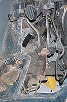 Detach
the two brake lines as the rear of the master cylinder. Very gently
depress the brake pedal to force out any remaining brake fluid. Pull
the cotter pin from the clevis which connects to the brake push rod.
Depress the clutch pedal, than slide out the clevis pin. The brake
pedal is now free from the master cylinder. Unscrew the bolts
holding the master cylinder to the frame being careful not to spill
any remaining brake fluid. Detach
the two brake lines as the rear of the master cylinder. Very gently
depress the brake pedal to force out any remaining brake fluid. Pull
the cotter pin from the clevis which connects to the brake push rod.
Depress the clutch pedal, than slide out the clevis pin. The brake
pedal is now free from the master cylinder. Unscrew the bolts
holding the master cylinder to the frame being careful not to spill
any remaining brake fluid.
Brake Line Removal.
Our P15 has the original steel lines. They are very rusty and need
replacement. From under the car, using two flare nut wrenches,
remove the steel line where it meets the rubber flex line directly
in front of the rear axle. A flare nut wrench supports the fitting
better is less likely to damage it. On the rear axle remove the two
steel lines from the T fitting. They also have clips holding them to
the rear axle. Working forward, pop off the clips holding the brake
line to the frame. In some cases they may be riveted to the frame
and can be pried open with a screwdriver. As your remove the old
lines make a note of the clip locations. I use chalk mark so I don?t
miss any during re-assembly. If any clips are broken now is the time
to replace them.
Moving forward, remove the first section from the master cylinder to
the stoplight switch junction block. Leave the junction mounted to
the frame while you unscrew the front two lines. Then steel line can
be removed. Working forward, two small bolted clips hold the
passenger side line. The clips are on the radiator cross member and
accessed from below. If your car has steel dust shields they may
need to be removed. Set the lines aside so you will have patterns
for the new lines. |
Parts list For Full Brake Overhaul
- Turned brake drums
- Brake shoes (Fitted to brake drums)
- Brake shoe springs and fasteners
- Brake lines (Premade set or generic replacement lines to be
custom fitted)
- Wheel cylinders (Recommend new, or have existing ones
re-sleeved. Also new rubber if using existing wheel cylinders.)
- Master cylinder (Recommend new, or have existing ones
re-sleeved. Also new rubber if using existing master cylinders.)
- Flex brake lines (Recommend new for all three locations)
- Front wheel seals
- Front wheel bearings
- Rear axle seals
- Brake fluid (Recommend Dot 5)
- Brake light pressure switch
- Brake grease
- Wheel bearing grease
|
Putting It Back Together
 Reassembly
is straight forward and fun, but you have some choices to make. Do
you want your replacement lines to look 100 percent factory original
or just be functional and safe? If you want 100% original than
purchase a brake line set from a reproduction supplier such as
Inline Tube or Classic Tube. These come ready to install, with all
the factory bends and tubing material of either steel or stainless
steel. They have all the stock details, such as the springs wrapped
around the lines where they connect to the master cylinder.
Stainless lines will last for the life of the car but cost more.
Steel lines can easily be bent with hand tools so "final
adjustments" are easy to accomplish. Stainless is more rigid and
harder to work but more durable. Reassembly
is straight forward and fun, but you have some choices to make. Do
you want your replacement lines to look 100 percent factory original
or just be functional and safe? If you want 100% original than
purchase a brake line set from a reproduction supplier such as
Inline Tube or Classic Tube. These come ready to install, with all
the factory bends and tubing material of either steel or stainless
steel. They have all the stock details, such as the springs wrapped
around the lines where they connect to the master cylinder.
Stainless lines will last for the life of the car but cost more.
Steel lines can easily be bent with hand tools so "final
adjustments" are easy to accomplish. Stainless is more rigid and
harder to work but more durable.
Another option is to use stock lengths of steel brake line from your
local parts store. Lengths usually run 12, 18, 26, 40 and 60 inches.
Use the old lines to match the size and shape.Make sure you purchase
steel brake lines. With these different lengths you can piece
together your replacement lines. Don?t forget to purchase couplings
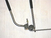
to join the different sections. A tube bender is also needed.
If you did not purchased a kit you will need to measure and
shape the lines using the old ones as a pattern. Use a tube bender
so you don?t kink or collapse a line. I highly recommend lever
action benders. They allow up to 180 degree bend and won?t damage
the steel line.
You will need a 45 degree double flare kit for the brake ends. All
brake lines MUST use a SAE 45 Degree double flare. Like tubing
benders there are many types available and most are junk. I
recommend using a lever action die kit like K Tool International
KTI70081.
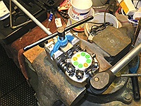
They are available from Eastwood and some sites rent them if you
purchase brake line supplies from them. They produce excellent
quality flares quickly and you don?t waste material which often
happens with cheaper flare tools. If you do make a mistake,
replace the line with a new one. Don?t use kinked lines. The
majority of lines are 3/16? diameter and can be shaped easily with
hand tools.
Considering the effort, tools and material costs associated with
replacing your brake lines it is usually cheaper to have the lines
duplicated by a professional service company like Inline Tube or
Classic Tube. They also offer the option of stainless steel tubing
which is more reliable long term and difficult for the amateur home
mechanic to work.
Take your brake drums to a machine shop to have them turned. This is
essential to successfully adjust the brake shoes. To my surprise on
my four vehicles the brake drums previously had never been turned so
the machinist had plenty of metal to work with.
|
Check The Anchor
The anchor bolt head has a stamped arrow pointing to the high side
of the cam. To adjust the brake shoes with the brake drum installed,
you must turn it from the backing plate side. Some anchor bolts have
wrench flats on the bolt ends for adjustment. If yours don?t, file
off two flats for a crescent wrench or cut a screwdriver slot in the
threaded end. I have had better luck using the wrench flats as you
can clip on a vise grip for easy adjustment. Also put an identifying
mark indicating the cam high point (The arrowhead on the face of the
anchor bolt).
Order new wheel cylinders, springs, flex hoses, master cylinder and
brake shoes. This is also the best time to repack the front wheel
bearing and rear axle bearings including replacing all the seals.
Check your service manual for the correct procedure for repacking
and adjustment. Nothing is worse than ruining a brake job because
you didn?t replace a $5.00 seal!
Starting with the rear axle replace the seal in the backing plate.
On the bench you can safely knock out the old one. The edges of the
seal should point toward the center of the car. Using a seal driver
seat the new seal squarely into the backing plate. Stake it at three
spots to lock it in position. Reinstall the axle shim and backing
plate. When bolting the backing plate don?t over torque and strip
the bolts. Take apart the wheel cylinders and lubricate with brake
fluid. Some manufacturers provide a pre-lube in the wheel cylinder
package. Bolt the new wheel cylinder in place. Crack the bleeder
just to be sure it is not jammed then close it.
Assemble the anchor bolts with the cup shaped retainer holding the
felt washer. They keep the shoes and anchor bolts from rusting
against the backing plate and often dry out. The felt should be
impregnated with a small amount of brake grease. If the felt is hard
I use a few drops of oil to soften it, then squeeze dry. If you
squeeze the felt and oil comes out you have too much. Only high
temperature brake grease should be used. Make sure your hands are
grease free before handling the brake shoes. Insert the anchor bolts
through the heel of the shoe and the spacers on the backside of the
shoe. Don?t forget the lock washer under the nut. The anchor bolts
and nuts should be tight enough to hold all parts in position, but
still be rotated with a crescent wrench to adjust the shoes.
At the brake shoe toe, line up the slots in the wheel cylinder pins.
Reinstall the two return springs. You can use brake spring pliers to
help guide them in. I have had better luck using a long thin
Phillips screwdriver to position them in the shoe hole. If the
spring hangs on the edge of the shoe use a rubber hammer to seat it.
Make sure the arrows on the anchor bolts are pointing toward each
other (fully retracted) and the minor adjusters are all the way in.
Coat the tapered axle shaft with a very thin coat of anti-seize or
brake grease. This will make drum removal easier next time. Slide
the brake drum on the axle. When fully seated align the keyway and
tap in the steel key. You can hold off on final tightening of the
lock washer and hub nut until after adjusting the brake shoes.
However the brake drum must be installed before you bleed the
brakes. For reference the axle nut is tighten to 150 foot pounds and
don?t forget the cotter pin when you finish the job.
Front brake assembly is similar with a few extra steps. Install on
the upper wheel cylinder the rubber flex line. The other end will be
attached to the chassis later. Prep the anchor felts same as the
rear. Install both wheel cylinders brake shoes and anchor bolts.
Leave the anchor bolts loose so you can align the parts. The arrows
should point at the other wheel cylinder. Install the short feeder
line from the top cylinder to the lower using new brake line. Again
make sure the minor adjusters are backed off. Reinstall the brake
return springs. When finished install the front drum and tighten the
wheel bearing nut per the service manual. The wheel should spin
easily. After bleeding the brakes you will remove the drum for brake
shoe adjustment.
You need to make a choice as to what type of brake fluid to use, Dot
3 or Dot 5 also known as silicone fluid. Dot 3 was originally used
is readily available at any parts store and is cheap. Downside is
the Dot 3 fluid will attract moisture from the air, leading to
corrosion and leaking of wheel cylinders. This is especially
problematic in cars that sit for periods of time. It will also
damage paint. Dot 5 does not attract moisture nor damage paint like
Dot 3. However it is more expensive. I have been using Dot 5 for
over 20 years and recommend it.
On the master cylinder make sure the pressure relief vent is clean
and open. It is a small hole in the bottom of the reservoir and must
be clean and free of any dirt. It can be seen when you take the
filler plug out and is directly below the opening. If you don?t see
the hole you will need to dissemble as the pressure relief vent is
clogged. This small hole allows the pressure to be relieved when the
brake pedal is released and unless fluid can flow easily through it
one or more of your wheel cylinders will lock up until that pressure
is released. On the bench fill the master cylinder with brake fluid
and pre-bleed it before installation. Follow the instructions with
the master cylinder, or if missing fill the reservoir and gently
push in the cylinder with a screwdriver. Discard the fluid expelled
from the master. Then plug the outlets. I use two small corks.
Re-bolt it to the frame. Carefully reattach the rod and clevis pin.
You will probably have to hold the clutch pedal down to get it in
place.
|
The last step is installing the new brake lines. This
step goes quickly if you have purchased a reproduction kit. Word of
warning: be very careful not to cross thread fitting, especially
where lines join brass "T" blocks. Use a flare nut wrench so you
don?t damage the flare nut. You should be able to run the nut almost
all the way down in the fitting without any tools. Also be sure to
hold the fitting with a wrench as you tighten the brake line into
it. They will crack or strip it you use too much force. The flex
lines are held on to the chassis bracket with a small "C" clip. You
must use two wrenches when attaching the steel line to the rubber
flex line. The flex line must not spin as you tighten the steel
line. Check the clearance on the rear axle flex line and make sure
it does not contact any chassis parts. Check your chalk marks to
make sure you have the lines securely reattached at all the hold
downs.
You will replace the following lines:
- Master to front brake switch Y block
- Front brake switch Y block to left flex line on chassis
- Front brake switch Y block to right flex line on chassis
- Master to rear flex line to rear axle Y block
- Rear axle Y block to driver side rear wheel cylinder
- Rear axle Y block to passenger side rear wheel cylinder
- Don?t forget to replace the brake switch.
|
The Home Stretch
The last two steps are to bleed and adjust the brakes. Bleeding
purges the air trapped in the new lines. If the air is not purged
the pedal will be spongy because air compresses under pressure. When
all the air is flushed out hydraulic fluid won?t compress resulting
in a firm brake pedal. First crack open then close all six bleeder
valves on the back of wheel cylinders. Pump the brake pedal a couple
times and don?t be surprised if it goes all the way to the floor.
Now add additional fluid to the master cylinder reservoir. What you
are doing is filling the new brake lines with fluid. Always start
with the longest brake line and finish with the shortest line.
Use this order for bleeding:
- Passenger side rear
- Driver side rear
- Passenger side front upper (rubber flex line attachment
point)
- Passenger side front lower
- Driver side front upper (rubber flex line attachment point)
- Driver side front lower
Bleeding is usually a two person job one at the wheel cylinder the
other at the master cylinder. NEVER depress the brake pedal with a
brake drum removed. The wheel cylinder will pop out spilling fluid
all over your brake shoes !
The standard procedure for 2 person bleeding starts with attaching a
piece of tubing to the wheel cylinder bleeder valve. Lead the other
end into a bottle filled with a couple inches of brake fluid. The
end of the tube MUST stay below the fluid in the bottle otherwise
you will such air back into the system. Have your helper pump the
brake pedal a few times and hold the pedal down. Crack open the
bleeder valve and air will squirt out of the line. With the bleeder
open the pedal will travel down. After a second or two, close the
bleeder valve. Pump up the brake pedal, hold and open the bleeder
again. When only fluid comes out, no bubbles, the line is clear and
you are ready to move to the next wheel cylinder. Keep a close eye
on the amount of fluid in the master cylinder reservoir. Keep it
full of fluid or you will be pumping air down the lines with the
master cylinder.
A word about bleeders. Bleeding the brake systems can be a
frustrating time consuming and sometimes expensive process. I
personally have had poor luck using the standard procedure mentioned
above. Many times the bleeder line pops off the bleeder spilling
fluid all over and allowing air back into lines. Often the helper
pumps the master cylinder dry forcing you to start all over again.
And sometimes I just couldn't get all the air out of the brake
lines. I have also tried using a vacuum pump with a reservoir for
the expelled fluid. This too was not very successful as maintaining
air tight contact between the vacuum hose and bleeder valve proved
problematic. After opening and closing the valve a couple times the
hose would start to lose it's tightness around the bleeder valve. I
now use a pressure bleeder from KD tools, Model 2910. Basically it
is a pump up lawn sprayer with a pressure relief gauge and valve. A
rubber fitting with a quick release air hose coupler is clamped to
the master cylinder filler hole providing an air tight fit. You
manually pump the bleeder up to 5 pounds of pressure and open the
line to the master cylinder. Brake fluid flows from the pressure
bleeder tank filling the master under pressure. Now the entire brake
system is under 5 pounds of pressure. You simple go to each bleeder
on the wheel cylinders, crack them open until no air bubbles are
seen, then move to the next wheel cylinder. I can do two passes on
all wheel cylinders and finish in less that ten minutes. It's also a
single person job and the large reservoir of brake fluid in the
bleeder tank keeps the master cylinder from running dry. Lastly the
pressurizing of the brake lines makes finding leaks easy.
Be aware the pedal will not firm up until ALL the air is expelled so
don?t get discouraged if things don?t seem to be getting better
after two or three wheel cylinders. It is my experience you will
have to make a least two passes through all the wheel cylinders
before they are fully bled. When the pedal holds firm the system is
full bled. Don?t be concerned about pedal height, as it will go up
as the brake shoes are adjusted.
|
Brake Shoe Adjustments
 These
cars have a "reputation" for poor brake performance. However the
reputation is unearned and can be attributed to improper brake shoe
adjustments. Because special equipment is required to do the job
correctly many mechanics without the correct tools just "finish the
job" by a quick adjustment of the minor adjusters. As mention
earlier the anchor bolt moves the heel of the shoe toward the brake
drum while the toe is adjusted by the minor adjuster. Two
adjustments are needed. A "minor" adjustment compensates for normal
wear and a "major" adjustment is done after installing new brake
shoes. To correctly adjust the shoes they first must be "centered"
to the axle on the backing plate so the drum will slide over the
shoes. Lockheed provided a tool which mounted of the axle spindle
while swinging an arc around the shoes. While the factory service
manual provides considerable detail regarding this adjustment you
must have a Brake Gauge Tool MT-19H tool. Unfortunately these tools
are impossible to find. These
cars have a "reputation" for poor brake performance. However the
reputation is unearned and can be attributed to improper brake shoe
adjustments. Because special equipment is required to do the job
correctly many mechanics without the correct tools just "finish the
job" by a quick adjustment of the minor adjusters. As mention
earlier the anchor bolt moves the heel of the shoe toward the brake
drum while the toe is adjusted by the minor adjuster. Two
adjustments are needed. A "minor" adjustment compensates for normal
wear and a "major" adjustment is done after installing new brake
shoes. To correctly adjust the shoes they first must be "centered"
to the axle on the backing plate so the drum will slide over the
shoes. Lockheed provided a tool which mounted of the axle spindle
while swinging an arc around the shoes. While the factory service
manual provides considerable detail regarding this adjustment you
must have a Brake Gauge Tool MT-19H tool. Unfortunately these tools
are impossible to find.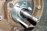 So what are options?
One option is an Ammco Model 1750 Brake Gage. Ammco 1750 tools are
the aftermarket replacement for the MT-19H adjuster. Similar
to the Lockheed tool they show up on Ebay on a regular basis. Don't
be surprised if the bidding reaches the $150.00 - $200.00 range.
They are quite popular with the Ford and Mercury owners which also
used Lockheed brakes in the 1930s. One advantage of the 1750 is you
can use it to "mic" the drum diameter and preset the gage to
compensate for the amount of metal removed by the machinist when the
drums are turned down. Check with other forum members in your area
as they may have one to borrow. Also this site will soon have one
available for rental.
The Plymouth Bulletin #229 (March-April 1998) has an article on how
to build a low cost replacement MT-19H. You can order reprints from
the Plymouth Owners Club store. Similar to the Plymouth Bulletin
approach is using a bearing, flangette and For the front spindle use
a Fafnir RA103-2 bearing and 62MS Flangette (bearing holder). Attach
your dial indicator to the flangette. For the rear brakes use a
clamp or magnetic holder to attach the dial indicator to the rear
axle. Then rotate the axle to center the shoes. Both of these
methods will allow you to quickly center the shoes relative to the
axle. The factory shop manual provides the required shoe to drum
clearances for your car. Using these clearance numbers will prevent
the shoe from dragging against the drum. 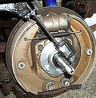 The
Ammco tool has a build in aid for this adjustment. If you use the
flangette you will have to do a bit of math using the dial gauge. I
usually install the drum, move the major adjuster out until the shoe
just contacts the drum. Then remove the drum and set the dial gauge
to indicate that diameter is the maximum. Center the shoes all the
way around to that diameter, them adjust the toe and heel diameter
with the anchors to the amount specified in the factory manual. Your
dial indicator will allow a very accurate adjustment. When finished
adjusting the shoes reinstall the drums as mentioned above. Check
the adjustment and torque on the front bearings and rear axle nuts.
Be sure all cotter pins are installed including those used on the
front anchor bolts. As you complete the adjustment procedure you
will notice the pedal height has gone up. (NEVER check the pedal
height with a brake drum removed!) This is because the distance the
wheel cylinder pistons have to travel before the shoes contact the
drum is less. Lastly check the master cylinder push rod adjustment.
The correct adjustment results in 1/8 to 1/4 pedal free play.This is
the distance the pedal will travel before the push rod touched the
master cylinder piston. The
Ammco tool has a build in aid for this adjustment. If you use the
flangette you will have to do a bit of math using the dial gauge. I
usually install the drum, move the major adjuster out until the shoe
just contacts the drum. Then remove the drum and set the dial gauge
to indicate that diameter is the maximum. Center the shoes all the
way around to that diameter, them adjust the toe and heel diameter
with the anchors to the amount specified in the factory manual. Your
dial indicator will allow a very accurate adjustment. When finished
adjusting the shoes reinstall the drums as mentioned above. Check
the adjustment and torque on the front bearings and rear axle nuts.
Be sure all cotter pins are installed including those used on the
front anchor bolts. As you complete the adjustment procedure you
will notice the pedal height has gone up. (NEVER check the pedal
height with a brake drum removed!) This is because the distance the
wheel cylinder pistons have to travel before the shoes contact the
drum is less. Lastly check the master cylinder push rod adjustment.
The correct adjustment results in 1/8 to 1/4 pedal free play.This is
the distance the pedal will travel before the push rod touched the
master cylinder piston.
A last option (and least desirable) is to use the following
adjustment procedure found in an old Clymer service manual. It
should only be used if no other option is available. The Downloads
page has a guide to assist you if you choose this method. It is
highly recommended you have a proper major adjustment done with the
correct tools by a professions shop if you use this adjustment for a
short term solution.
- Turn the cam nut (minor adjuster) so shoe is fully retracted
inward.
- Turn anchor bolts so both arrows are facing each other. With
2 wheel cylinders, the arrow faces the corresponding wheel
cylinder.
- Install the brake drum and tighten retaining nut.
- Identify the wheel cylinder/shoe configuration. Note
adjustment direction for the cam nut and anchor as mentioned in
the service manual. Note the direction to decreases clearance
between the shoe and drum.
- Turn anchor until shoe "heel" drags on drum.
- Next turn the cam nut (minor adjuster) to bring shoe "toe"
into drum contact. This will cause shoe "heel" to lose contact.
You need a light touch for this step. It is easy to go too far
with the cam nut and overshoot, locking the drum with the minor
adjuster.
- Turn anchor again direction of arrow until shoe "heel" drags
on drum again.
- Repeat step #6.
- Repeat step #5 and #6 until cam nut adjustment no longer
frees the shoe "heel". Tighten anchor bolt nut and reinsert a
cotter pin, if used. My experience with new brake shoes is it
only takes 2-3 passes and the shoe is adjusted.
- Repeat procedure for all shoes
- When finished, install cotter pins on all anchor bolts.
Make one more inspection for leaks, playing close attention to the
"T" junctions.
|
Onto a road test.
First, from 25 mph make 8 or 10 mild stops. Follow this with 8-10
more at 45 mph at 1 mile intervals. Try to avoid severe use during
the first hundred miles or so. This will allow the shoes to seat
without overheating them. After the first 1000 miles check the minor
brake adjustment. With a properly adjusted and functioning brake
system I think you will be surprised at your braking performance.
And congratulations, you are now on the road for years of safe and
reliable brake service.
|