Leaderboard

Popular Content
Showing content with the highest reputation on 10/19/2019 in all areas
-
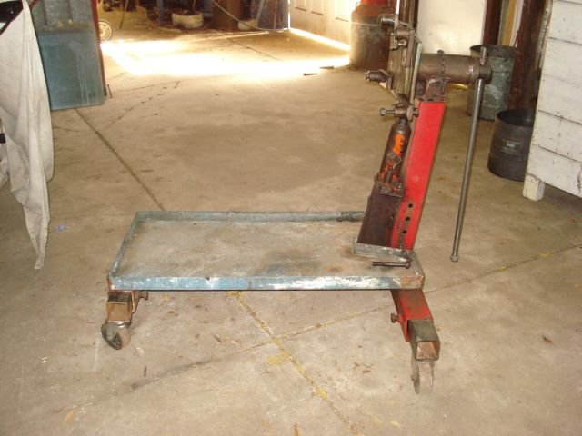
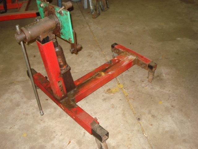
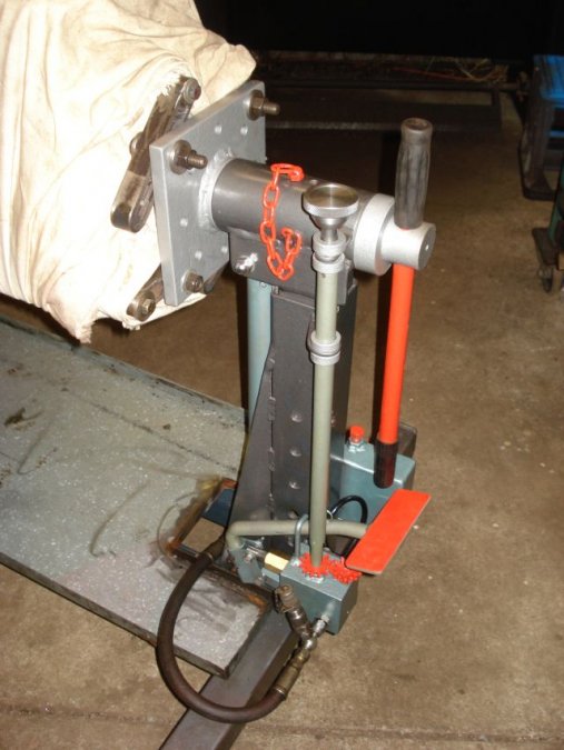
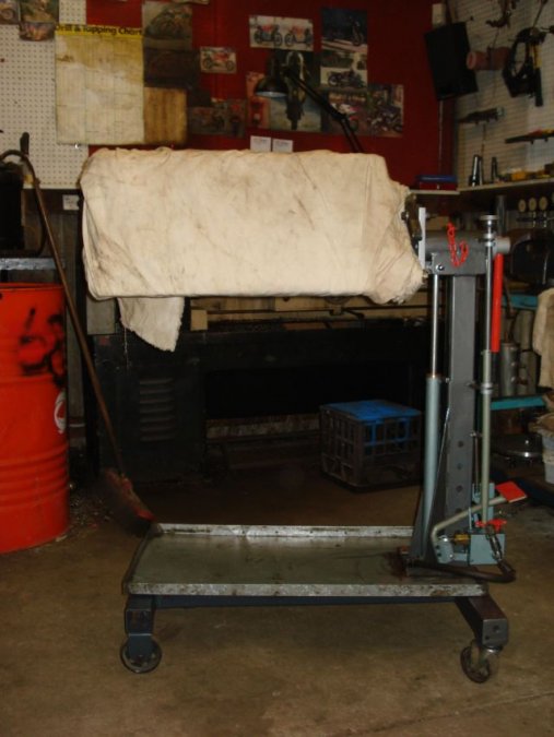
Have to agree about going for the larger model. I was never happy with either of my stands (though I was swinging 4 and 6 cylinder diesels off them) so I built my own. The first was built from the base of a 2 ton engine crane I was given. (The rest was mounted on the back of my ute). I also fitted the bottle jack to give some height adjustability. The second I went totally over the top. About 12" adjustability and dose not flex. Very stable.
 3 points
 -
Lots of small towns need the revenue.. Oh, wait, what am I saying.. They merely want to make sure the highways are safe from inattentive drivers...3 points
-
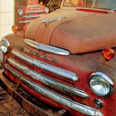
The mechanic that I bought my '47 Desoto from seven years ago came over today and he got the engine to the point of turning over without plugs. Numbers five and six cylinders worked but the others didn't, and he said the valves were probably stuck. We shot some more PB80 into the cylinders and are letting it set and try again later. Even though we didn't get it running at least the engine turned over. And I had done quite a bit of work on the engine accessories the past year getting it ready. Some wiring. The starter that was such a bitch to remove and replace worked. My cheap $59.99 Fleet Farm 6v battery worked. All in all I'm pretty jazzed. I just hope we can un-stick the valves. My friend works at a classic car museum as a buyer. They have a complete shop there where they restore the cars they bring in. He goes out and buys cars if they check out. I've been on this board for all of those seven years and I want to thank everybody for their patience in getting me this far. I haven't always been a model member but all families have their ups and downs. Will keep you posted.2 points
-
Here's the circuit diagram for the radio mod. Really the only mod to the radio is the two 1k ohm resistors into the volume pot and desoldering the radio antenna input and routing it through a two way switch. The 10k ohm resistor to ground was suggested in another forum, but i didn't need it in the end.
 2 points
 -
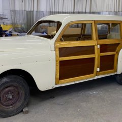
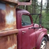
What a perfect shot! Enjoyed working on my neighbor's '49 Plymouth today while he is away in Florida. He said if I work on the car I can drive it, so you bet I will!2 points
-
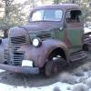
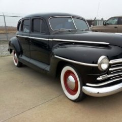
Friday October 18: Drove my son and I downtown for a haircut. My barber likes the Meadowbrook. I'd say our maple is at peak color today ?2 points
-
Dad, Your Ol Bessy has dancing shoes and LS motor/trans is out of the way.

 2 points
 -
car club meeting last night so I tossed the big boy fender extensions on...
 2 points
 -
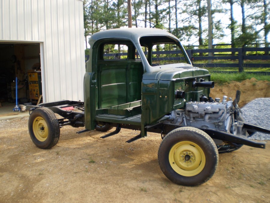
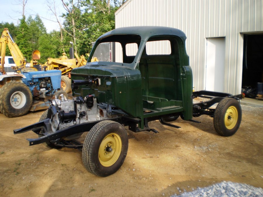
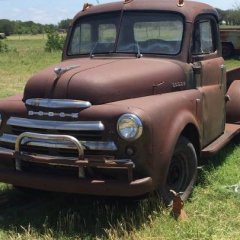
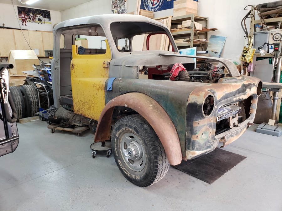
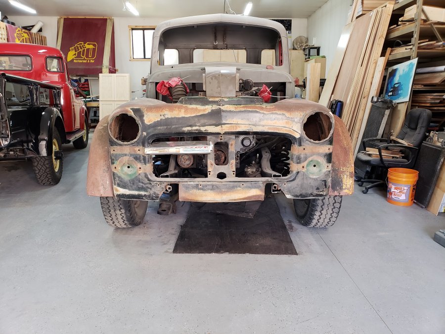
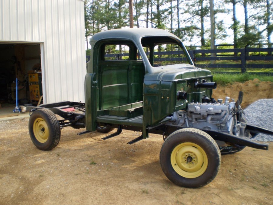
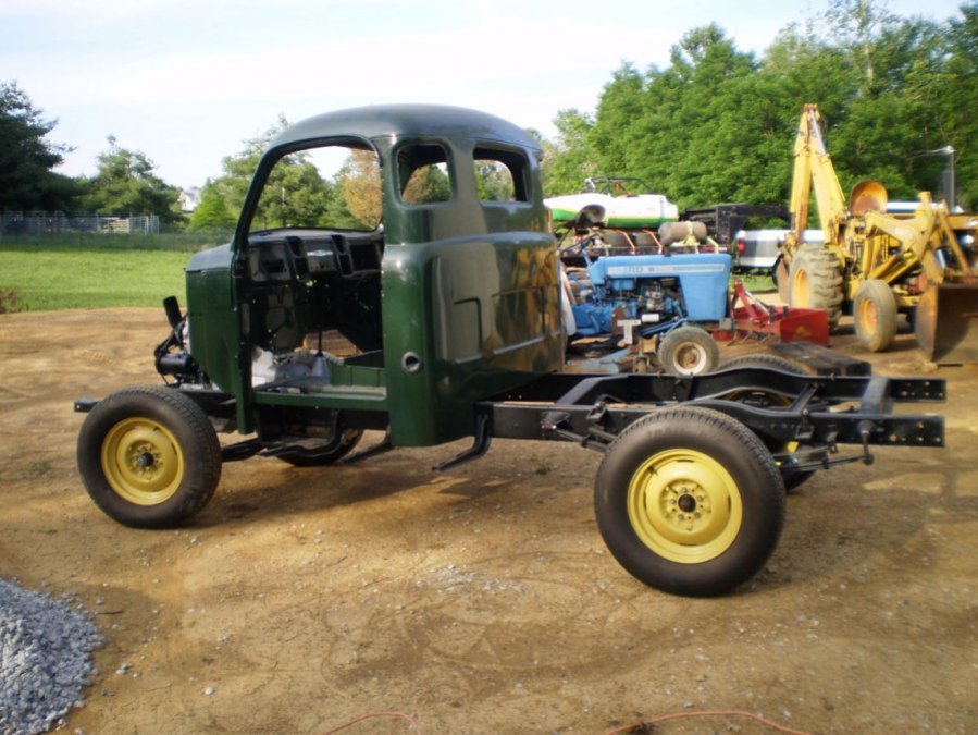
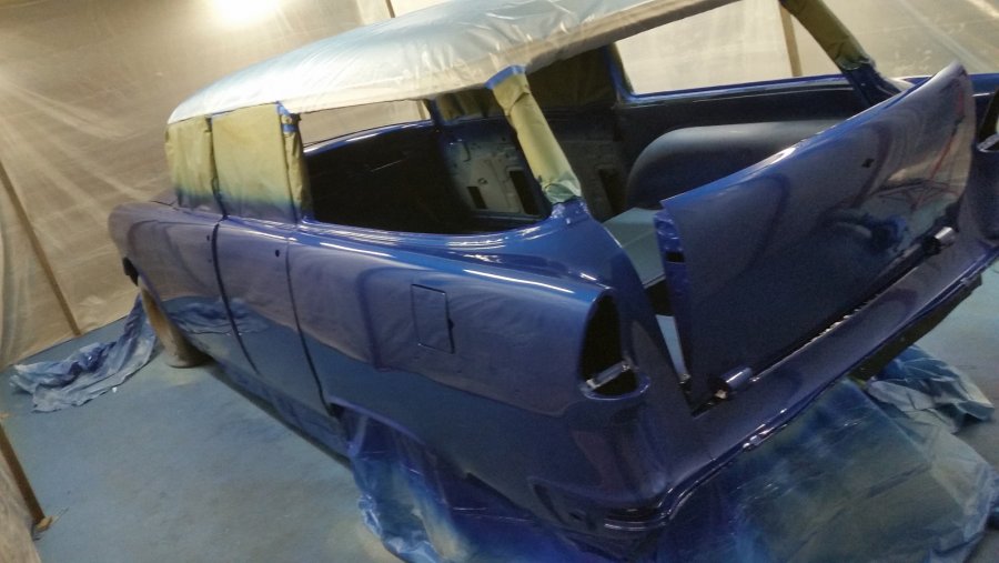
I think maybe it’s time I started a build thread for my 51 B3B. I’ve actually been a member of this forum (or it’s earlier derivatives) since the late 90s. I bought the truck in Hailey Idaho in 1996 and trailered it home to Lincoln Nebraska. Over the next couple of years I proceeded to dismantle the truck and started the rebuild process. By early 2000 I had a rolling chassis with engine and cab installed and all sheet metal painted ready for installation. It was at this point things sort of ground to a halt. I proceeded to change jobs (working overseas for a number of years) and then moved, with the truck still in pieces, from Lincoln to Dallas, then from Dallas to Little Rock Arkansas and finally to Richmond Kentucky. During the years from 2001 till now I’ve really not had the opportunity to work on the truck with the exception of a few sort periods of time. There were multiple times over the years I considered selling but just couldn’t bring myself to do so. In 1999 the engine was rebuilt by a respected dirt track engine builder. It has been bored 0.060” over (with 3 cylinders requiring sleeves) and has a new 230 cam. Around the same timeframe I had the transmission rebuilt by a local shop along with the differential pumpkin. The frame was sandblasted and painted as was just about every component I touched. I built my own sandblast cabinet and small wall mounted paint booth, both of which have also made every move with the truck. I spent 2008 in Pasadena (on short term work assignment) and while there I fabricated a complete wiring harness using wire and connectors from YnZ while using modified diagrams that someone on this forum had posted. Also during that period I rebuilt two carburetors for use on the Offenhauser dual intake manifold that I’m installing. Over the intervening years I would watch for parts on ebay and elsewhere. I managed to come up with a NOS steering wheel, NOS floor mat, NOS fuel gauge, NOS temp gauge, NOS coolant heater valve, NOS rear bumper, NOS amp gauge, and NOS speedometer cable. I might have a few others but can’t think of them off the top of my head. Oh yeah, I think I have a NOS front bumper as well. So as it sits today the truck is a finished rolling chassis with cab and engine installed. All of the sheet metal has been leaning against the wall for years and is covered in dust and grime. The rolling chassis desperately needs to be hosed down and scrubbed clean. There are five new (in 2000) radial tires that probably have a grand total of 500 feet on them but will need to be replaced if/when the truck is ever ready to finally hit the road. When I bought the truck in 1996 I was able to drive it up onto the trailer in Hailey and drove it off the trailer in Lincoln. Since then the truck has traveled 2,711 miles and none of it under its own power! I still don’t have much free time to work on the truck but I’m going to at least make the effort to tinker with it from time to time. The first step is to gather up all of the parts boxes and sort through them to see if I have the parts I’m supposed to have. I think that will be a good winter task. The pictures are from 2009 after it arrived from Arkansas getting ready to be pushed in to my new shop. You can bet I will be having lots of questions as time goes on. Anyway, that’s my story and I’m sticking to it Here's a link to the steering box rebuild that I did for the very badly worn original steering box.
 1 point
 -
Got new glass from DCM along with new runners and installed them today. Putting on the runners was not as bad as I thought it might be, hammers near glass gives one pause even if they are rubber. A little Dawn on the window tape and the runners hammered on pretty as you please. I also put on the door panels with arm rests and am pleased the locks work from the inside and the key works on the passenger side. Once I get my bed installed, taillights and running boards it will be time to drive and have fun! The end of an almost three year frame up build is getting close.
 1 point
 -
I was NOT critizing anyone's work but I do question methods and (cap)abilities...perhaps that is the engineering career side of my brain. Your question has been asked and answered many times and it would 'appear' that each new query has the expectation of a paint-by-number answer/approach. If you are the builder then you need to evaulate where the frames are closest to being in the same place and then figure out how to blend them in a safe and structurally sound fashion.1 point
-
Sure thing. The module came from Amazon, I know they are out of stock of the module I used, but most Bluetooth module receivers will work. The one I used has a 5-35 voltage input range, so that's perfect for our trucks. Now the wrinkle in my truck is that I'm 6 volt positive ground, so you can't simply pick up the power direct from the truck wiring, but fortunately most Bluetooth modules can be powered off a micro USB connection. This completely isolates the amplifier positive ground to the Bluetooth module negative ground. What I did was to get a small rechargeable USB stick, it doesn't need to be very big since the Bluetooth module only takes about 35 milliamp, so even a small USB battery stick can power it for a couple of weeks. So you get a USB cable, plug it into the module via a USB battery stick, that powers the Bluetooth module. Then you take the module and solder three wires onto the module (this is going to be the audio feed to the radio). One wire is left channel, one right channel and the last is the ground wire. The radios are mono, so you need to combine the left and right channel from the Bluetooth into a single feed to the radio, that's done with a couple of 1k resistors. (see diagram), then you find the input into the volume control input, desolder the radio input wire and add in a two way switch, one side of the input to the switch will come from the radio signal, the other side will be the combined left and right signal from the bluetooth module. So you can switch between the two inputs. Find a small project box (I used a small project that I had lying around), mount the bluetooth module in the box, the micro USB cable goes to the USB battery stick, the audio cable goes into the radio. Solder it up, then I mounted the project box to the side of the radio via velcro. Install the radio and then test it.1 point
-
Just finished.
 1 point
 -
The seal on the A pillar where the hinges is no longer available so following up on an older post ( http://p15-d24.com/topic/50474-finally-done-1951-dodge-d39-business-coupe/page/2/?tab=comments#comment-535913 I thought in clear up how I handled some of the questions posed. I used the same Garage door seal. I cut it length wise about a 1/4” from the center ridge. Then I glued the factory flat edge to the car (using contact cement) with this bend facing down. Then glued the metal core to that piece and finally glued the other half (with the bent factory edge facing down and slightly over the previous piece. Below are pics of (1) the profile of the rubber as purchased, (2) showing where I cut (the pic with the scissors in hand), and a few others showing the orientation - note the metal core is not shown.


 1 point
 -
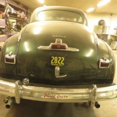
Later wifey asked me to drop off some books at the library. What better car to run an errand with. At the library parking lot in this pic.1 point
-
Car ran good as usual. I might take it out later for a night ride ?1 point
-
I will tell you my theory I learned while was in the tire business. But I dealt mostly with modern radials, not sure how much is different between bias and radials. The proper amount of air in the tire, is the amount that is needed to carry the load. Just saying, If the left front tire on my hoopty goes down to 20 pounds psi, and the tire is squatting, it is under inflated. Same time, if it is not mounted on the hoopty, then it has enough air to carry the sidewalls and is not underinflated. The air pressure is directly related to the amount of weight the tire is carrying. A modern tire may say max pressure 35 psi. If you put 35 psi in then and mount them on a 2 ton truck and add weight, they are over loaded. The sidewalls will squat and down the road the tires will fail. If you put the same tires on the front of a hot rod roadster, very little weight on them, maybe 20 pounds psi is all you need to carry the weight? Only saying, it is the air pressure that holds up the tires, You need your tires side walls to stand up and take the load. The max air pressure on the side of the tire is same as a 1 ton chain hoist, you can lift anything up to 1 ton, over that you are on your own. But you can lift any weight you want under 1 ton. If your tires say max 35 psi, you can run less then that, just make sure your tires sidewalls are standing up to the job. You may find that 28psi or 30 psi, gives you the best ride and the tires work best ... you just need to play here to find what you like. 35 psi in same situation may ride like a wooden buck board. Even though I am used to working with radials, I see no reason why bias is any different on weight and air pressure.1 point
-
pressure are greatly different between bias ply as was factory when your car was built and the modern radials...as B4Ya says, default to the tire makers chart..1 point
-
Follow what the tire manufacturer states.1 point
-
I've come to the conclusion that the original style pinion seal is not a seal at all. It's a cruel hoax perpetrated on the poor hobbyist! I am putting together a spare differential (with an alternate ratio) for my Suburban. OMG! This is the nastiest seal I've ever tried to install! Pinion seals should not be that hard to install. Modern stuff with silicone outer rims are designed to go in with a little more than thumb pressure. There is no way you can get an original in while on your back under the car. Yet that is exactly how most pinion seals are changed. So after a frustrating failure I went to my local NAPA looking for a modern seal. The counterman was in no mood to re-engineer a 67 year old Plymouth so what I got was the listed seal for my car. The outer edge has the dry sealant coating and there is no felt dust seal. It's tap-in to fit in the housing and a reasonable thumb push fit for the yoke. You could easily install this seal while on your back under the car....if you could get the old out! The NAPA part number 18880 price $20 so for $70 (with the "Speedi Sleeve") you can be assured of a leak free differential and you won't be frustrated.1 point
-
Try pic attached here. Does that work? Thanks @RobertKB1 point
-
Here's one I have on my 42 Dodge Business Coupe. I didn't find a proper 2 bbl carb soon enough so I got a 1 to 2 bbl adapter and installed it upside down so I could drive the car until I found a good 2 bbl carb. Well......that was years ago and it's still like this. Runs great !!!
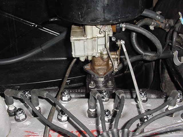 1 point
 -
Sometimes people true up the surfaces on the intake and exhaust manifolds themselves. Not sure about the surfaces on the block where the manifolds mount. If you did that, it would of course require removal of the studs. The crankshaft main bearing bores/saddles occasionally require line boring to get them all to line up with each other, but that's not a must on every engine. It just depends on the condition of those bores. I don't know of any other surfaces on the block that are routinely machined (aside from things you probably already know about, such as cylinders, valve seats, etc.). If a gasket surface, such as the ones you mentioned, is damaged, of course the shop can machine it to correct the issue, assuming it's not too badly damaged. There is another thread on this site (can't recall which thread), where the gentleman describes having to braze some damage (maybe a crack?) to the thermostat housing mating surface on the top of the head, and his shop machined it nice and flat again.1 point
-
Compression ratio varied for all engines over the years, but if we take a smaller engine and a larger engine having the same compression ratio as each other, then the larger engine will see a bump in compression when the smaller engine's head is installed onto the larger engine. For example, if we take a 7:1 218 head (25" engine) and put it on a larger 25" engine that also had a 7:1 ratio with its own head, the result will be a higher compression ratio. Of course, you also have to take into account any milling of the head that may have been done over the years. I'm using the head off a 251 that came out of an early 60s Power Wagon and putting it on my 265. The manuals say the stock compression ratio for that 251 in the Power Wagon was 7.2:1. When I cc'd the combustion chambers and ran the calculations, I came up with 7.2:1 for that 251, so that all made sense (for this reason and others, I believe that engine had never been rebuilt, by the way.) I then ran the numbers for that head on a 265 and got about 7.75:1. I don't recall if that included boring the block oversize or not, which would have the effect of raising the compression a bit more. Of course, now I've since had the head milled just enough to make the gasket surface flat again, which was about 0.015", and I cc'd the chambers again, but have not run the numbers on compression ratio yet. However, the cc numbers didnt change much (I think they went from around 98cc each before milling to about 94 or 96cc after milling - going by memory), so I expect the increase in compression to be mild, which is what I wanted. I suspect it'll be about 8:1 now, and I don't want it to be up much higher than that. I also had the block decked, but I haven't taken the effect of that into account yet. I doubt it'll be much .1 point
-
Keep it on the low guys, he'll get a big head and others will send him more stuff and I'll never get my 4 set done! LOL, just kidding! Now let's brow beat him into buying another pilothouse!1 point
-
Hey Jeff, a few comments on that hesitation thing. When the gas pedal is pushed to the floor, you open the throttle plate to allow more vacum to pull gas through the different circuits. The top plate is the choke, when warmed up it should be wide open, if not find out why and fix it.(sometimes a short throttle cable can cause idle fluctuations with the engine moving in a different direction than the cab) If it's a hard pedal push....the accelerator pump is allowed to shoot a steady stream of gas into the system. When you floor it (WOT-wide open throttle)...the vacum drops to zero and needs to build up to continue sucking gas. To help during this vacum drop, some carbs have a power circuit, power system or power valve.The way most work is vacum keeps the circuit closed....when vacum drops...it opens up usally letting raw gas pour in til vacum rises to close it. The B&B has a Step-Up Jet that does this, sometimes called the Power Piston. The idle mixture screw has to be set right, to get the other circuits to run right. If not, you have multiple WOT issues (meaning no fuel). "Set right" means getting the most vacum you can at idle. Not sure you have a Carter B&B, but this is still a good read: 1948 Chrysler Reference Guide On The Story Of The Carburetor And of course the youtube videos on rebuilding a B&B: 48D1 point