Leaderboard


Popular Content
Showing content with the highest reputation on 05/18/2019 in all areas
-
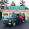
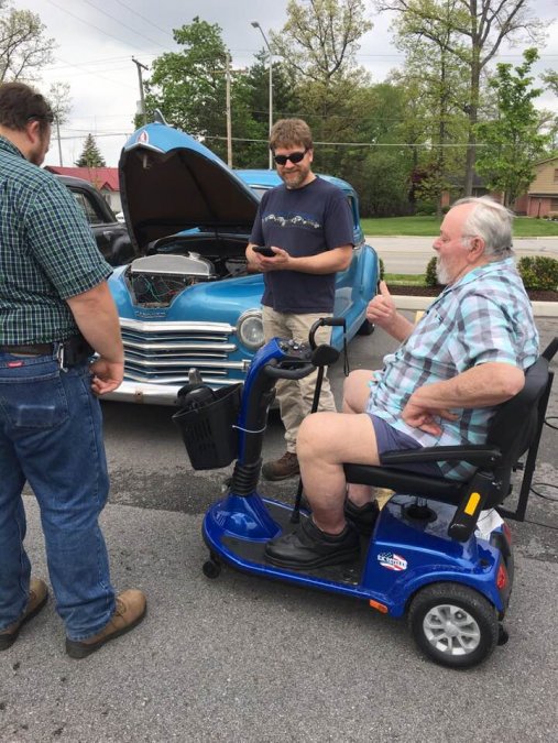
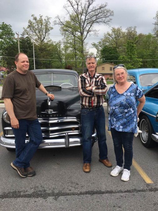
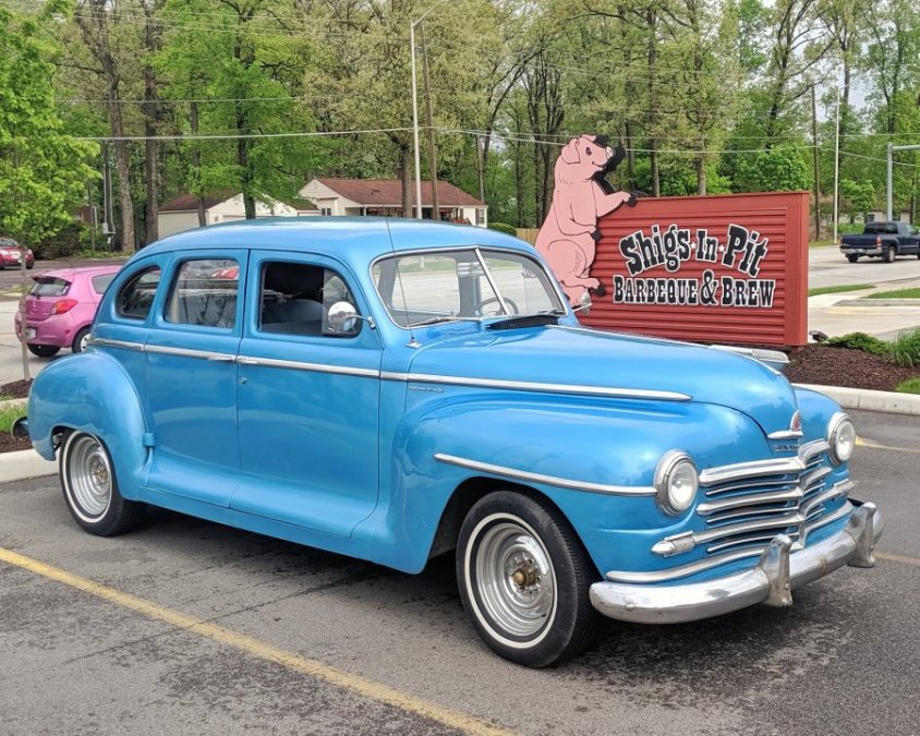
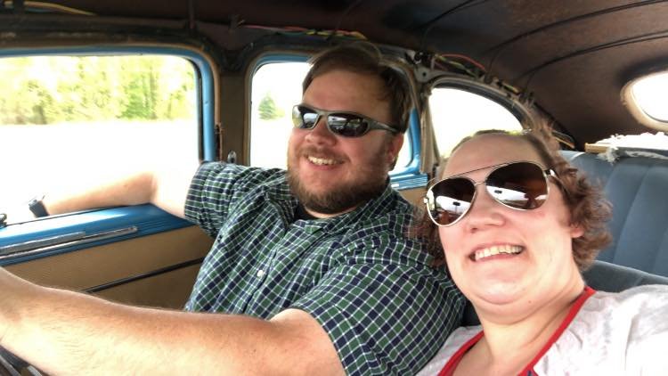
Don Coatney Jason Hoffman and his girlfriend Tamisha Matus drove my Plymouth to Fort Wayne for a nice visit. Also with Todd Bracik, Bob and Wanda VanBuskirk, Keven Reeves and his wife Kristin Reeves.


 2 points
 -
My head hurts.........2 points
-
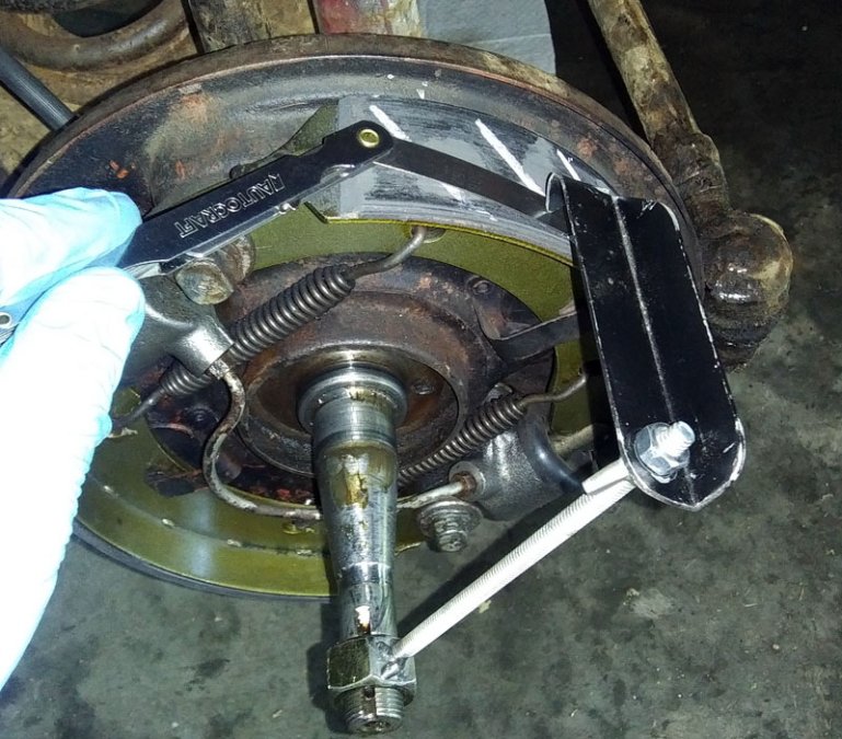
In a previous thread I showed how I made a brake adjustment tool using a length of steel tubing, some all-thread and a piece of angle. The tool worked fairly well but had some inherent imprecision due to the tubing not being a real tight fit on the axle threads. This was really obvious on the rear axles due to the threads being worn. I've modified the tool and it now works very nicely and accurately. Instead of the all-thread being welded to steel tube, it is welded to a 3/4"-16 nut. This removes any significant play in the indicator. Before removing the wheel drum, one minor cam adjuster is tightened enough to create noticeable drag on the drum. The drum is then removed and the brake tool is threaded onto the axle. The pointer is located over the portion of the shoe that contacted the drum which indicates the ID of the drum and adjusted for a snug fit on the shoe. If you want to get really fancy a 0.006" feeler gauge can be inserted between the pointer and shoe. I tried chalking the shoe to assist with indicating the high point during the initial adjustment but didn't find it to be of any advantage. Notice how these brand new shoes have not yet worn enough to have full contact with the drum. I'll readjust the brakes after some miles have accumulated on the shoes. Once the pointer is adjusted to match the high point of the shoe that was adjusted against the drum, the tool is swept over each shoe so the major and minor cam adjustments can be set so each shoe is concentric with the drum. Hopefully this will remove some of the mystery of adjusting the brakes and provide visual confirmation of proper adjustment.
 1 point
 -
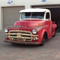
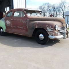
G'day. I found your site just now so I thought I would slip in while no one is looking. I have this 1955 D49 Aussie built Kingsway in pretty good nic, not the hemi only a flat six. Im not going to mod it to much just tyres and rims and set her low. so any suggestions on wheel and tyre widths would be appreciated. Cheers
 1 point
 -
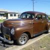
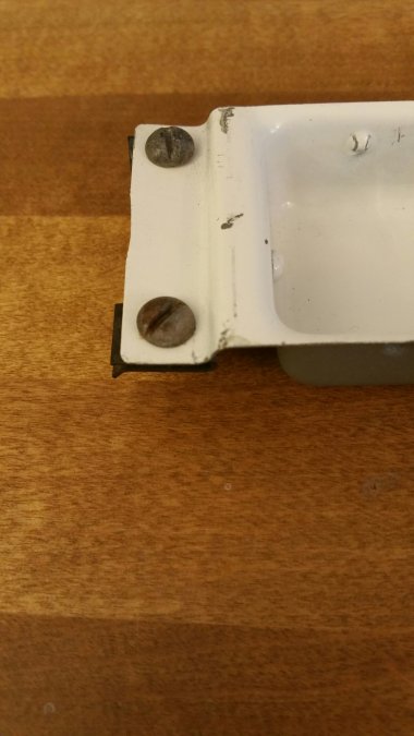
Here are what mine look like. From their appearance, I think they are original.
 1 point
 -
Ralph I would humbly suggest that you buy a new battery first. I have had the experience of my starter not disengaging when I had a weak battery. A new battery might solve the problem... You need a new one anyway ?1 point
-
That happened to me with a starter that was maybe a year past a rebuild, returned it and was told a faulty bendix drive was the culprit. They replaced it and has been fine for 2 plus years.1 point
-
Good catch and fix. Now just replace that wire nut with a proper connector and all will be good. Wire nuts have no place in vehicle electrical systems.1 point
-
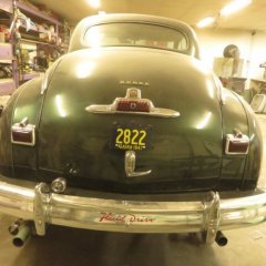
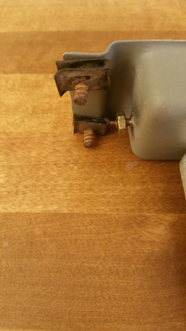
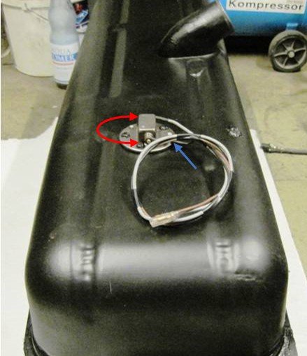
Cool, I would like to have your `backward fuel system` , too ! The more mls you drive, the fuller is the tank ........ just joking As Plymouthy said, just swap the wires (red arrow). It will not harm your units. That is not a swap of + / - , but a indication reverse. Ground is (if additionally installed / blue arrow) for example at the body of the sender unit. [2-wire sending unit]
 1 point
 -
I used a Runtz on my gas gauge. It worked for about a day and then quit working. Took the dead Runtz out and have been running 12 volts to my gauge for years now. No problem.1 point
-
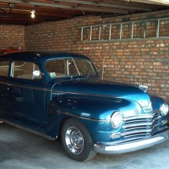
Glad to hear you got it working. I’m soon to be doing a 12v upgrade to the 48 Plymouth super deluxe. Was just checking these out this morning. My dad was an automotive electrician so a lot of these old wiring repairs sure bring both good memories. Also glad to have the help from all the members here when I get stumped1 point
-
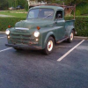
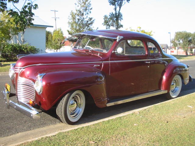
Like a dope I sold the coupe........the colour we think was a mid 90's Oz Ford or maybe Japanese car colour, there are a few different tho' similar hues and they really pop with some chrome and the whitewalls.....I matched the paint reasonably well when I painted the sun visor and considering that you couldn't get directly above the car to compare the colours I was happy enough.....I lowered it enough to what I think improved the appearance but not looking silly laying frame which I don't like..................in some light there was a pinkish hue to it............andyd
 1 point
 -
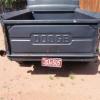
I bought this at auction Sunday. It's a 51 B-3-D. I started bid at $100 and a guy behind me went to $500. I let him buy it. As I turned to talk to him, he was saying to his wife that now he has to get rid of the tractor part. We split the cost, I drove it a mile home, disconnected the Bale Handler and loaded it on his flatbed with my forklift. And my 47 WD-21 in the background.


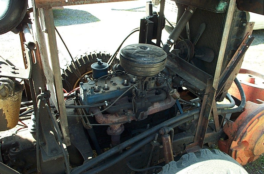 1 point
 -
That upper crack area is fairly common on Mopar flatheads.... It can be caused by pulling up too hard on the block deck area... this.by over tightening a 7/16" X 20 fine thread stud.... 55lbs is the max torque on a head stud nut ... Never torque to 60-70 Ft lbs on a stud/fine thread nut fastener being used on a cylinder head... .60-70Ft Lbs torque only the 7/16 X 14 course head bolts?1 point
-
the dome light installs centered over the rear window, about 3 inches above the back panel. This places the dome light in the middle of the original headliner curve, as the light attached to the original cardboard. The light was grounded by a 10 inch lead to the cab in the same line as the back panel push pins, towards the driver side. One of the small improvements I plan on doing is to mount this dome light on a sheet metal bracket rather than attach to the headliner, possibly making the bracket the ground strap. From Bunn's Restorer's & Collector's Reference, a decent photo is on p.37, another is on p.137, and a brief view can be seen on p.134 & p.143.1 point